
 My Inquiry
 My Account


Analog Devices Inc./Maxim Integrated MAX3353EEUE+
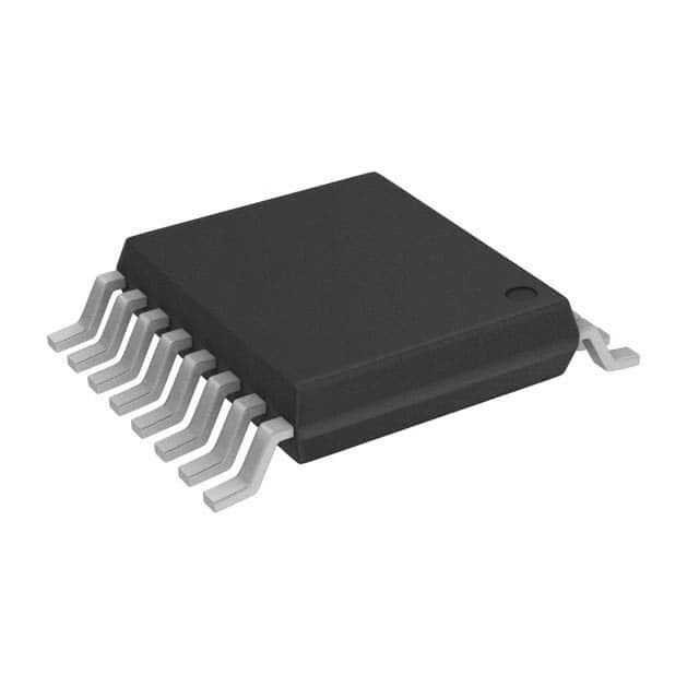
- Part No.:
- MAX3353EEUE+
- Manufacturer:
- Analog Devices Inc./Maxim Integrated
- Category:
- Special Purpose Regulators
- Package:
- 16-TSSOP (0.173", 4.40mm Width)
- Datasheet:
-
 MAX3353EEUE+.pdf
- Description:
- IC REG CHRG PMP USB 2OUT 16TSSOP
- Quantity:
- Payment:

- Shipping:

Inventory:1,353
Please send an inquiry. Send us your inquiry, and we will respond immediately.
Product details
Overview
MAX3353EEUE+ from Maxim Integrated is a USB On-the-Go (OTG) regulated charge pump IC with integrated switchable pullup/pulldown resistors, I²C-compatible control interface, and ±15kV ESD protection on VBUS, ID_IN, D+, and D−. It enables dual-role USB OTG functionality in low-voltage systems (VL = +1.65V to VCC), supports SRP/HNP protocols, delivers 8mA VBUS output at 4.63–5.25V, and operates from VCC = +2.6V to +5.5V. It is used in mobile phones and digital cameras to eliminate host PC dependency during peripheral interconnection.
For engineers reviewing the MAX3353EEUE+ datasheet, MAX3353EEUE+ pinout, MAX3353EEUE+ application, or MAX3353EEUE+ equivalent, this page provides verified technical context for USB OTG session management, VBUS power control, I²C register-based configuration, and dual-role device signaling-critical for embedded USB OTG transceiver integration in battery-powered portable electronics.
Technical Context
The MAX3353EEUE+ implements a regulated flying-capacitor charge pump delivering OTG-compliant VBUS (4.63–5.25V, 8mA) from input VCC as low as +2.6V. Its internal comparators monitor VBUS_VALID (4.40–4.63V), SESSION_VALID (1.0–1.8V), and B_SESSION_END (0.4–0.6V) thresholds to support Session Request Protocol (SRP) and Host Negotiation Protocol (HNP).
It integrates programmable 1.425–1.575kΩ D+/D− pullup resistors and 14.25–15.75kΩ pulldown resistors, controlled via I²C registers, alongside an ID detector, level-shifted SDA/SCL/INT/ID_OUT interface (VL-referenced), and autoconnect/autoresponse logic for timing-critical HNP handshaking without firmware intervention.
Key Specifications
| Parameter | Value and Actual Design Meaning |
|---|---|
| VCC Supply Range | +2.6V to +5.5V - Enables operation from single Li-ion or dual-cell alkaline supplies without external LDO. |
| VBUS Output Voltage | 4.63V to 5.25V at 0–8mA - Meets USB OTG VBUS specification for reliable bus enumeration and power delivery. |
| VBUS Output Current | 8mA min - Sufficient to drive USB OTG session initiation and sustain signaling during SRP/HNP negotiation. |
| D+/D− Pullup Resistance | 1.425kΩ to 1.575kΩ - Matches USB 1.1/2.0 peripheral pullup tolerance for compliant device detection. |
| I²C Clock Frequency | Up to 400kHz - Supports fast register read/write for real-time OTG role switching and status monitoring. |
| ESD Protection | ±15kV HBM on VBUS, ID_IN, D+, D− - Eliminates need for external TVS diodes in handheld consumer designs. |
| Operating Temperature | −40°C to +85°C - Qualified for industrial-grade portable electronics including smartphones and digital cameras. |
Pinout & Package
MAX3353EEUE+ is housed in a 16-pin TSSOP package (5.0mm × 4.4mm, 0.65mm pitch), optimized for space-constrained portable PCBs. Pin functions are electrically validated per Maxim's official datasheet Rev 1 (10/03).
| Pin/Terminal | Circuit Role | Design Meaning |
|---|---|---|
| VCC (Pin 1) | Charge-pump power input | Supplies regulated VBUS; requires 1µF bypass capacitor to GND for stable pumping operation. |
| VL (Pin 2) | Logic supply reference | Sets I²C interface voltage thresholds (VIH = 0.67×VL, VOL ≤ 0.4V); supports 1.65V–VCC logic levels. |
| SDA (Pin 3) | I²C bidirectional data line | Open-drain or push-pull configurable; level-shifted to VL for interfacing with low-voltage microcontrollers. |
| ADD (Pin 4) | I²C slave address select | Internal 110kΩ pulldown sets default I²C address; tied high to change address for multi-device buses. |
| SCL (Pin 5) | I²C clock input | Accepts up to 400kHz clock; tolerant of voltages >VL, enabling mixed-voltage system integration. |
| INT (Pin 6) | Active-low interrupt output | Signals VBUS_VALID, SESSION_VALID, or SESSION_END events; configurable open-drain or push-pull. |
| ID_OUT (Pin 7) | Level-translated ID status | VL-referenced mirror of ID_IN state; indicates A-device (GND) or B-device (floating) role to host controller. |
| VTRM (Pin 8) | USB termination supply | +3.0V to +3.6V input for internal 1.5kΩ D+/D− pullups; decoupled with 0.1µF capacitor. |
| D− (Pin 9) | USB differential data (−) | ±15kV ESD protected; connected to switchable 1.5kΩ pullup or 15kΩ pulldown per OTG role. |
| D+ (Pin 10) | USB differential data (+) | ±15kV ESD protected; higher-priority pullup prevents bus contention when both D+/D− switches active. |
| ID_IN (Pin 11) | OTG device ID input | Internally pulled up to VCC; floating = B-device, grounded = A-device; level-shifted to VL at ID_OUT. |
| N.C. (Pin 12) | No connection | Not bonded; must remain unconnected to avoid parasitic coupling or EMI. |
| GND (Pin 13) | Analog/digital ground | Single-point return for VCC, VL, VTRM, and USB signals; critical for noise-free comparator operation. |
| C− (Pin 14) | Charge-pump flying capacitor (−) | Connects to negative terminal of 0.1µF ceramic flying capacitor; layout symmetry minimizes ripple. |
| C+ (Pin 15) | Charge-pump flying capacitor (+) | Connects to positive terminal of 0.1µF ceramic flying capacitor; forms switched-capacitor doubler stage. |
| VBUS (Pin 16) | OTG bus power output | Delivers regulated 5V to USB port; supports backdrive up to +6V; requires 1µF minimum bypass capacitor. |
Key Features
| Feature | Design Value |
|---|---|
| Regulated charge pump | Generates stable 4.63–5.25V VBUS from +2.6V VCC input, enabling USB OTG operation in low-voltage battery systems. |
| Switchable D+/D− resistors | Individually controllable 1.425kΩ pullups and 14.25kΩ pulldowns via I²C registers-no external resistors needed for OTG role switching. |
| Integrated VBUS comparators | Three precision comparators (VBUS_VALID, SESSION_VALID, B_SESSION_END) enable autonomous SRP/HNP state detection without MCU polling. |
| I²C-compatible control interface | 400kHz 2-wire bus with address-select pin (ADD) allows daisy-chaining multiple MAX3353EEUE+ devices on one controller. |
| Autoconnect and autoresponse logic | Hardware-accelerated HNP signaling: automatic D+ pullup assertion (A-device) and SE0 generation (B-device) within defined timing windows. |
| ±15kV ESD protection | Fully protects VBUS, ID_IN, D+, and D− pins per Human Body Model-reduces BOM count and board area in consumer handhelds. |
Applications
| Mobile Phone OTG Adapter | Digital Camera Direct Print |
|---|---|
|
Use Scenario: Smartphone acts as USB host to connect to flash drives or keyboards via OTG cable. IC Role / Device Role / Timing Role: MAX3353EEUE+ supplies VBUS, detects ID_IN state to determine A/B role, and asserts D+ pullup to signal host capability within <1ms. Use Value: Enables seamless host-peripheral role negotiation without firmware delay, supporting USB 2.0 full-speed enumeration. |
Use Scenario: Digital camera connects directly to USB photo printer without PC intermediary. IC Role / Device Role / Timing Role: MAX3353EEUE+ monitors VBUS for session validity and triggers INT on SESSION_VALID transition to initiate print handshake. Use Value: Guarantees reliable session establishment under variable load conditions, meeting USB OTG Supplement v1.0 timing requirements. |
| MP3 Player File Transfer | PDAs Peripheral Docking |
|
Use Scenario: MP3 player transfers music files to USB mass storage device using OTG mode. IC Role / Device Role / Timing Role: MAX3353EEUE+ executes SRP by pulsing VBUS via internal current source (VBUS_CHG1), driving 13µF load >2.1V within 90ms. Use Value: Self-timed VBUS pulse ensures compliance with PC-safe SRP limits (<2.0V into 96µF), preventing host port damage. |
Use Scenario: PDA docks into cradle acting as USB host to sync with peripherals like barcode scanners. IC Role / Device Role / Timing Role: MAX3353EEUE+ provides level-shifted ID_OUT and INT outputs to PDA's 1.8V GPIO, enabling real-time role arbitration. Use Value: VL-referenced interface eliminates external level translators, reducing component count and power consumption. |
Equivalent & Alternatives
The following parts are listed as comparable options for similar USB OTG charge pump applications.
| Alternative Part | Technical Difference | Application Difference | Selection Advice |
|---|---|---|---|
| MAX3353EEBP-T | Same die, 5×4 UCSP package (B20-4); 0.4mm pitch, 1.6mm² footprint vs. TSSOP's 22mm². | Targeted for ultra-compact wearables or hearing aids where PCB area is constrained. | Select MAX3353EEBP-T only if board space is critical and reflow profile supports UCSP assembly. |
| TPS650532RGER | Triple-output PMIC with integrated USB OTG charge pump (5V/500mA), but lacks switchable D+/D− resistors and ID detection. | Requires external pullup/pulldown resistors and GPIO-based ID sensing; suited for systems with dedicated USB PHY. | Choose TPS650532RGER only when additional DC/DC rails (1.2V/1.8V/3.3V) are needed alongside VBUS, and discrete resistor routing is acceptable. |
Compared with MAX3353EEUE+, the MAX3353EEBP-T offers identical electrical performance in a miniature chip-scale package, while the TPS650532RGER trades integrated OTG signaling for broader power management-making MAX3353EEUE+ optimal for cost-sensitive, function-specific OTG add-on modules.
Availability
MAX3353EEUE+ is available at Aetrix Electronics and suitable for mobile phone OTG adapters, digital camera direct-print interfaces, MP3 player file transfer systems, PDAs peripheral docking, and photo printers requiring stable component supply across extended temperature ranges and long production lifecycles.
Supply support for MAX3353EEUE+ includes scheduled delivery planning, volume procurement assistance, BOM continuity management, traceable sourcing, and lifecycle availability coordination for OEM customers, industrial embedded developers, connected-device designers, and electronics production programs.
Manufacturer
Maxim Integrated (now part of Analog Devices) is a semiconductor company specializing in high-performance analog, mixed-signal, and power management ICs for industrial, communications, and consumer applications.
The MAX3353E product line was designed specifically to simplify USB On-the-Go implementation in portable electronics by integrating charge pumping, role detection, and bus signaling into a single compact IC-reducing design complexity and bill-of-materials cost.
FAQ
What is the primary function of the MAX3353EEUE+ in a USB OTG system?
The MAX3353EEUE+ serves as a dedicated USB OTG companion IC that generates regulated VBUS power, manages D+/D− pullup/pulldown resistors for host/peripheral role identification, detects ID_IN state to determine A/B device role, and supports SRP/HNP protocols via integrated comparators and interrupt logic. It enables low-voltage portable devices to operate as dual-role USB hosts or peripherals without requiring a PC.
Does the MAX3353EEUE+ require external pullup resistors on D+ and D− lines?
No, the MAX3353EEUE+ integrates switchable 1.425kΩ pullup and 14.25kΩ pulldown resistors on both D+ and D− lines, controlled via I²C registers. These meet USB 2.0 OTG specifications and eliminate the need for external discrete resistors-reducing PCB area, BOM count, and potential layout errors in space-constrained designs.
How does the MAX3353EEUE+ support Session Request Protocol (SRP)?
The MAX3353EEUE+ supports SRP through its self-timed VBUS pulsing feature: setting VBUS_CHG1 = 1 activates an internal current source that pulses VBUS to >2.1V into a 13µF load within 90ms (for A-device detection) while limiting voltage to <2.0V into a 96µF load (to protect PC hosts). This complies with USB OTG Supplement v1.0 SRP requirements without MCU timing overhead.
What is the significance of the VL pin on the MAX3353EEUE+?
The VL pin on the MAX3353EEUE+ sets the logic reference voltage for SDA, SCL, INT, and ID_OUT signals, allowing interoperability with low-voltage microcontrollers (1.65V–VCC). It defines VIH (0.67×VL) and VOL (≤0.4V), enabling direct connection to 1.8V or 2.5V system logic without external level shifters-critical for power-efficient portable designs.
Can the MAX3353EEUE+ operate with a VCC supply below 3.0V?
Yes, the MAX3353EEUE+ operates with VCC as low as +2.6V while still delivering a compliant 4.63–5.25V VBUS output at 8mA. This capability allows direct integration with single-cell Li-ion batteries (2.7–4.2V) or two-cell alkaline supplies, eliminating the need for intermediate boost converters in battery-powered OTG accessories.
MAX3353EEUE+ Specifications
- Product attributes
- Attribute value
- Manufacturer:
- Analog Devices Inc./Maxim Integrated
- Series:
- -
- Package/Case:
- 16-TSSOP (0.173", 4.40mm Width)
- Packaging:
- Tube
- Product Status:
- Active
- Applications:
- Charge Pump, USB
- Voltage - Input:
- 2.6V ~ 5.5V
- Number of Outputs:
- 2
- Voltage - Output:
- -
- Operating Temperature:
- -40°C ~ 85°C
- Grade:
- -
- Qualification:
- -
- Mounting Type:
- Surface Mount
- Supplier Device Package:
- 16-TSSOP
MAX3353EEUE+ FAQ
1.How can I place an order for MAX3353EEUE+ through Aetrix?
Please submit a Request for Quotation (RFQ) for MAX3353EEUE+ on Aetrix. Our sales agent will provide a competitive quotation and guide you through the order confirmation once you accept the terms.
2.Are the price and stock information for MAX3353EEUE+ reliable?
The price and inventory of MAX3353EEUE+ are updated periodically and may fluctuate due to market conditions. Stock and pricing data are typically refreshed every 24 hours. Quotation validity for MAX3353EEUE+ is usually 5 days.
3.What payment methods are accepted for MAX3353EEUE+?
We accept Wire Transfer, PayPal, Credit Card, Western Union, MoneyGram, and Escrow for MAX3353EEUE+ transactions.
Note: Certain payment methods may incur a processing fee.
4.How is shipping managed for MAX3353EEUE+?
MAX3353EEUE+ orders can be shipped via leading logistics carriers, including DHL, UPS, FedEx, TNT, or Registered Mail.
Once your MAX3353EEUE+ order is processed, you will receive an email with the shipment details and tracking number.
Note: Tracking information may take up to 24 hours to appear. Express delivery typically takes 3–5 business days.
5.How can I obtain technical support or documentation for MAX3353EEUE+?
For technical support, including MAX3353EEUE+ datasheets, pinout diagrams, or application guidance, please contact our engineering support team. They can provide detailed documentation and assistance for your MAX3353EEUE+ requirements.
6.How does Aetrix verify that MAX3353EEUE+ is sourced from the original manufacturer or authorized distributors?
All MAX3353EEUE+ products on Aetrix are procured from qualified distributors and authorized channels. Our dedicated quality assurance team conducts strict verification, including traceability checks and, if necessary, third-party testing. This ensures that MAX3353EEUE+ meets industry standards.
7.What is the process for return or replacement of MAX3353EEUE+?
All MAX3353EEUE+ units undergo pre-shipment inspection (PSI). If there is an issue with MAX3353EEUE+, returns or replacements are accepted under the following conditions:
1.Quantity discrepancies, incorrect items, or visible external defects (such as breakage or corrosion), acknowledged by Aetrix.
2.The issue is reported within 90 days of delivery.
3.The MAX3353EEUE+ part is unused and in its original packaging.
Return procedure for MAX3353EEUE+:
1.Submit a request within 90 days.
2.Obtain a Return Material Authorization (RMA) from Aetrix.
MAX3353EEUE+ Tags

-
TPS51206DSQR
Texas Instruments

-
TPS51200DRCR
Texas Instruments
-
TPS51200DRCT
Texas Instruments

-
TPS62740DSSR
Texas Instruments

-
TPS51100DGQR
Texas Instruments

-
NCP51200MNTXG
onsemi
-
NCP51400MNTXG
onsemi

-
RT9026GSP
Richtek USA Inc.

-
LP2998MRX/NOPB
Texas Instruments
-
TPS51200QDRCRQ1
Texas Instruments

-
DPA423GN-TL
Power Integrations
-
LM10011SD/NOPB
Texas Instruments
Tech Hub

A practical engineering guide to 3.3V and 5V logic compatibility, input thresholds, resistor dividers, translator ICs, MOSFET level shifting, I2C pull-ups, timing limits and power-sequencing risks.

The 74HC595 uses push-pull logic outputs, while the TPIC6B595 uses 50 V open-drain DMOS sinks for higher-power loads. This guide compares timing, current limits, 3.3 V interfacing, load wiring, thermal…

The 74HC595 converts serial data into eight stable parallel outputs. This guide covers pin functions, shift and storage timing, OE and MR behavior, drive-current limits, cascading, voltage compatibilit…

A technical comparison of level-sensitive latches and edge-triggered flip-flops, covering timing windows, setup and hold limits, master–slave operation, time borrowing, race-through, HDL inference and…

A D latch stores one bit while Enable controls when data can pass. This reference covers gate-level operation, truth tables, transparency, setup and hold timing, LE versus OE, common ICs and practical …

An SR latch stores one bit through cross-coupled feedback. This engineering reference covers NOR and NAND implementations, truth tables, forbidden-state recovery, gated operation, switch debouncing, fa…

Latch circuits retain one bit through feedback. This technical reference covers SR and D latches, truth tables, transparency, timing limits, latch-versus-flip-flop behavior, applications and common log…

An engineering guide to LED driver operation, constant-current and constant-voltage outputs, linear and switching topologies, dimming, IC selection, calculations, replacement compatibility, and fault c…

Operational amplifier guide covering op amp basics, feedback, ideal vs real op amps, common configurations, buffer circuits, offset, bias current, gain-bandwidth, slew rate, rail-to-rail limits and sel…

Jumper cables guide covering safe connection order, red and black clamp placement, final ground connection, cable gauge, length, clamp quality, copper vs CCA cables, jump starter comparison and battery…


