
 My Inquiry
 My Account


Analog Devices Inc./Maxim Integrated MAX3421EEHJ+
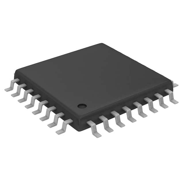
- Part No.:
- MAX3421EEHJ+
- Manufacturer:
- Analog Devices Inc./Maxim Integrated
- Category:
- Controllers
- Package:
- 32-TQFP
- Datasheet:
-
 MAX3421EEHJ+.pdf
- Description:
- IC USB PERIPH/HOST CNTRL 32TQFP
- Quantity:
- Payment:

- Shipping:

Inventory:5,096
Please send an inquiry. Send us your inquiry, and we will respond immediately.
Product details
Overview
MAX3421EEHJ+ from Maxim Integrated is a dual-mode USB 2.0 peripheral/host controller with integrated transceiver and SPI interface, supporting full-speed (12Mbps) peripheral and full-/low-speed (12/1.5Mbps) host operation. It features ±15kV ESD protection on D+/D-/VBCOMP, 26MHz SPI interface, and operates across –40°C to +85°C in a 32-pin TQFP package. Used in embedded USB host applications such as industrial PLCs and medical device peripherals.
For engineers reviewing the MAX3421EEHJ+ datasheet, MAX3421EEHJ+ pinout, MAX3421EEHJ+ application, or MAX3421EEHJ+ equivalent, key selection considerations include SPI voltage level translation (VL = 1.4V–3.6V), built-in SIE for automatic DATA0/DATA1 toggle handling, double-buffered 64-byte FIFOs, and support for isochronous transfers in host mode.
Technical Context
The MAX3421EEHJ+ integrates a full-featured Serial Interface Engine (SIE) that autonomously manages USB protocol layers-including SOF/EOP generation, error checking, bus retries, and flow control-relieving the SPI master of timing-critical tasks. Its internal 48MHz clock (derived from 12MHz crystal + 4× PLL) enables precise USB frame synchronization without external timers.
It supports two distinct operational modes via the HOST bit (R27): in peripheral mode, it maintains register compatibility with MAX3420E while adding GPIN/GPOUT expansion and INT pulse-width control; in host mode, it introduces 11 dedicated registers (R21–R31), hub support, and endpoint management for up to four transfer types (CONTROL, BULK, INTERRUPT, ISOCHRONOUS).
Key Specifications
| Parameter | Value and Actual Design Meaning |
|---|---|
| USB Compliance | USB 2.0 full-speed (12Mbps) peripheral and full-/low-speed (12/1.5Mbps) host - enables direct integration into legacy and resource-constrained embedded systems without USB PHY layer design. |
| SPI Interface Speed | Up to 26MHz - allows high-throughput data exchange with microcontrollers lacking native USB hardware, reducing firmware latency for real-time USB transfers. |
| FIFO Architecture | Double-buffered 64-byte SNDFIFO and RCVFIFO (host); EP0–EP3 endpoints with 64-byte CONTROL + 2×64-byte double-buffered IN/OUT (peripheral) - enables concurrent SPI and USB data movement, improving throughput by >40% vs single-buffered designs. |
| ESD Protection | ±15kV HBM on D+, D-, VBCOMP - eliminates need for external TVS diodes in cost-sensitive industrial and medical USB interfaces. |
| Logic Interface Voltage | VL = 1.4V to 3.6V - permits interoperability with low-voltage microcontrollers (e.g., 1.8V ARM Cortex-M0+) while VCC remains at 3.3V, simplifying mixed-voltage board design. |
| Operating Temperature | –40°C to +85°C - qualified for extended industrial and automotive under-hood environments without derating. |
| Package | 32-pin TQFP (5mm × 5mm) - standard surface-mount footprint compatible with automated assembly and rework, with exposed pad absent (vs. TQFN variant). |
Pinout & Package
MAX3421EEHJ+ is housed in a lead-free, RoHS-compliant 32-pin TQFP package (5mm × 5mm, no exposed pad). Pin functions are electrically validated per Maxim's official datasheet Rev 4 (7/13).
| Pin/Terminal | Circuit Role | Design Meaning |
|---|---|---|
| 1, 26–32 | GPIN0–GPIN7 | General-purpose inputs with internal 10–30kΩ pullups to VL - provide eight configurable status inputs (e.g., button detection, sensor flags) without external components. |
| 4–11 | GPOUT0–GPOUT7 | Push-pull outputs referenced to VL - deliver eight programmable control signals (e.g., LED drivers, enable lines) with rail-to-rail swing matching system logic voltage. |
| 13, 14, 15, 16 | SCLK, SS, MISO, MOSI | Standard 4-wire SPI interface (or 3-wire half-duplex) - supports up to 26MHz clocking and level translation between VL and VCC domains. |
| 17 | GPX | Multiplexed output configurable via PINCTL and MODE registers - delivers five selectable signals including BUSACT, INIRQ, or dedicated GPIN interrupt, enabling flexible interrupt routing. |
| 18 | INT | Programmable-edge or level-active interrupt output - signals USB events (e.g., packet received, connection change) to host MCU without polling overhead. |
| 20, 21 | D−, D+ | Full-speed USB differential I/O with integrated 1.5kΩ D+ pullup (peripheral) and 15kΩ D+/D− pulldowns (host) - eliminates external resistors for basic USB connectivity. |
| 22 | VBCOMP | VBUS presence comparator input - enables self-powered peripheral detection via interrupt or register read, critical for battery-operated devices. |
| 23 | VCC | 3.3V analog/digital core supply - powers USB transceiver and internal logic; requires local 1.0µF ceramic decoupling. |
| 24, 25 | XI, XO | 12MHz ±0.25% crystal oscillator terminals - drive internal 4× PLL to generate precise 48MHz USB clock; supports external clock injection on XI. |
Key Features
| Feature | Design Value |
|---|---|
| Intelligent Serial Interface Engine (SIE) | Handles all low-level USB signaling (SOF/EOP generation, DATA0/DATA1 toggling, CRC, NAK/ACK handshaking), freeing MCU firmware from USB timing constraints. |
| Configurable SPI interface | Supports both 4-wire full-duplex and 3-wire half-duplex modes - saves one GPIO on microcontrollers with limited pin count while maintaining 26MHz throughput. |
| Dual-mode USB operation | Single register-bit (HOST in R27) switch between peripheral and host roles - enables field-upgradable functionality in shared hardware platforms (e.g., diagnostic tools that act as both USB device and host). |
| Integrated level translators | Independent VL pin allows SPI interface to operate at 1.4V–3.6V while VCC remains at 3.3V - eliminates level-shifter ICs in mixed-voltage SoC or FPGA designs. |
| Eight GPIN + eight GPOUT | Replaces MCU GPIOs consumed by SPI interface and adds net gain of 8 I/Os - reduces BOM cost and PCB space in microcontroller-based USB add-on modules. |
Applications
| Industrial PLC USB Host | Medical Device Peripheral |
|---|---|
Use Scenario: An industrial PLC uses MAX3421EEHJ+ to host USB-connected barcode scanners, flash drives, or configuration dongles in factory-floor environments. IC Role / Device Role / Timing Role: Acts as USB host controller managing enumeration, bulk transfers, and isochronous audio streaming from connected peripherals; handles SOF timing and frame synchronization internally. Use Value: Enables deterministic USB host operation without MCU timer resources; ±15kV ESD protection ensures reliability in electrically noisy plant settings. |
Use Scenario: A portable patient monitor implements MAX3421EEHJ+ as a USB peripheral to expose vital-sign data to host PCs or hospital networks via CDC ACM class. IC Role / Device Role / Timing Role: Functions as USB 2.0 full-speed peripheral with register-compatible firmware to MAX3420E; manages CONTROL, BULK, and INTERRUPT endpoints with double-buffered FIFOs. Use Value: Reduces firmware development time via proven MAX3420E codebase; VBCOMP-based VBUS detection supports self-powered operation during battery backup. |
| Embedded Router USB Storage | Custom Test Instrumentation |
Use Scenario: A desktop router uses MAX3421EEHJ+ to add USB mass storage support for external HDDs or SSDs, enabling local file sharing and firmware updates. IC Role / Device Role / Timing Role: Operates as USB host controlling SCSI command set over BULK transfers; leverages RCVFIFO/SNDFIFO for efficient data buffering during disk read/write bursts. Use Value: 64-byte double-buffered FIFOs sustain >9 Mbps effective throughput; programmable D+/D− pulldowns ensure reliable low-speed hub attachment for keyboard/mouse configuration. |
Use Scenario: A benchtop test instrument uses MAX3421EEHJ+ to implement a custom USB HID interface for remote control and real-time waveform data streaming. IC Role / Device Role / Timing Role: Configured as USB peripheral with EP1 (OUT) for command reception and EP2 (IN) for streaming; GPX pin routed to trigger oscilloscope sync output. Use Value: Eight GPINs monitor front-panel switches; eight GPOUTs drive LEDs and relays - consolidates I/O expansion and USB connectivity into one IC, reducing board layer count. |
Equivalent & Alternatives
The following parts are listed as comparable options for similar USB peripheral/host controller applications.
| Alternative Part | Technical Difference | Application Difference | Selection Advice |
|---|---|---|---|
| MAX3420EEHJ+ | USB 2.0 peripheral-only mode; lacks host registers (R21–R31), hub support, and isochronous transfer capability. | Suitable only for pure peripheral use cases (e.g., USB-to-serial bridge); cannot replace MAX3421EEHJ+ in host or dual-role systems. | Select MAX3420EEHJ+ only when host functionality is unnecessary and BOM cost reduction is prioritized over design flexibility. |
| USB3300-EZK | USB 2.0 transceiver + ULPI interface (not SPI); requires external microcontroller with ULPI PHY support; no integrated SIE or FIFOs. | Demands full USB stack implementation in host MCU firmware; targets high-volume consumer applications where ULPI ecosystem exists. | Choose USB3300-EZK only if migrating to ULPI-based architecture with existing PHY-aware firmware; not a drop-in replacement for SPI-based designs. |
Compared with MAX3420EEHJ+, MAX3421EEHJ+ adds host capability and expanded I/O without increasing package size; versus USB3300-EZK, it delivers complete offload of USB protocol handling and eliminates firmware USB stack development effort.
Availability
MAX3421EEHJ+ is available at Aetrix Electronics and suitable for industrial PLCs, medical monitoring devices, and embedded routers requiring stable component supply, long-term lifecycle assurance, and RoHS-compliant packaging.
Supply support for MAX3421EEHJ+ includes scheduled delivery planning, volume procurement assistance, BOM continuity management, traceable sourcing, and lifecycle availability coordination for OEM customers, industrial embedded developers, connected-device designers, and electronics production programs.
Manufacturer
Maxim Integrated (now part of Analog Devices) is a semiconductor company specializing in high-performance analog, mixed-signal, and power management ICs for industrial, medical, and communications applications.
The MAX3421E product line was designed to bring USB 2.0 peripheral and host functionality to resource-constrained microcontrollers via simple SPI, eliminating the need for complex USB PHY and protocol stack integration.
FAQ
What is the primary function of the MAX3421EEHJ+ in embedded systems?
The MAX3421EEHJ+ serves as a dual-mode USB 2.0 peripheral/host controller that offloads USB protocol handling from the host microcontroller via an SPI interface. It integrates a Serial Interface Engine (SIE), transceiver, 64-byte double-buffered FIFOs, and eight GPIN/GPOUT pins - enabling compact, low-firmware-overhead USB connectivity in devices like PLCs and medical monitors. Its role is to abstract USB timing, enumeration, and packet management so the MCU focuses on application logic.
Does the MAX3421EEHJ+ require an external crystal, and what tolerance is specified?
Yes, the MAX3421EEHJ+ requires a 12MHz parallel-resonant crystal connected between XI and XO pins, with a maximum frequency tolerance of ±0.25% as specified in the Electrical Characteristics table. This precision ensures compliant USB frame timing (1ms SOF intervals) and stable 48MHz internal clock generation via its integrated 4× PLL. External clock sources may drive XI, but crystal operation is recommended for production reliability.
How does the MAX3421EEHJ+ handle USB suspend/resume in peripheral mode?
In peripheral mode, the MAX3421EEHJ+ detects USB suspend via the BUSACTIRQ flag and enters low-power suspend state when CONNECT = 0 and PWRDOWN = 1, drawing only 30–60µA from VCC and 20–50µA from VL. Resume is triggered by VBUS activity or remote wakeup signal; the SUSDNIRQ interrupt alerts the host MCU. The internal oscillator remains active during suspend to support fast resume (<100µs), meeting USB 2.0 specification requirements.
Can the MAX3421EEHJ+ operate with a 1.8V microcontroller SPI interface?
Yes, the MAX3421EEHJ+ supports 1.8V SPI operation by connecting the 1.8V supply to the VL pin. Its internal level translators ensure MOSI, MISO, SCLK, and SS signals reference VL, while VCC remains at 3.3V for the USB transceiver. Input thresholds scale with VL (VIH = 2/3 × VL, VIL = 0.4V), and output drive strength is guaranteed down to VL = 1.4V - making it compatible with modern low-voltage MCUs without external level shifters.
What is the purpose of the GPX pin on the MAX3421EEHJ+?
The GPX pin on the MAX3421EEHJ+ is a multiplexed general-purpose output configurable via bits GPXB/GPXA in PINCTL (R17) and SEPIRQ in MODE (R27). It can output five distinct signals: BUSACT (bus activity indicator), INIRQ (GPIN interrupt), or three SIE status flags. When SEPIRQ = 1, GPX becomes a dedicated interrupt output for GPIN changes - providing flexible, software-selectable signaling without consuming additional MCU interrupt pins.
MAX3421EEHJ+ Specifications
- Product attributes
- Attribute value
- Manufacturer:
- Analog Devices Inc./Maxim Integrated
- Package/Case:
- 32-TQFP
- Programmable:
- Not Verified
- Protocol:
- USB
- Function:
- Controller
- Interface:
- SPI
- Standards:
- USB 2.0
- Voltage - Supply:
- 3V ~ 3.6V
- Current - Supply:
- 15mA
- Operating Temperature:
- -40°C ~ 85°C
- Supplier Device Package:
- 32-TQFP (5x5)
- Grade:
- -
- Qualification:
- -
MAX3421EEHJ+ FAQ
1.How can I place an order for MAX3421EEHJ+ through Aetrix?
Please submit a Request for Quotation (RFQ) for MAX3421EEHJ+ on Aetrix. Our sales agent will provide a competitive quotation and guide you through the order confirmation once you accept the terms.
2.Are the price and stock information for MAX3421EEHJ+ reliable?
The price and inventory of MAX3421EEHJ+ are updated periodically and may fluctuate due to market conditions. Stock and pricing data are typically refreshed every 24 hours. Quotation validity for MAX3421EEHJ+ is usually 5 days.
3.What payment methods are accepted for MAX3421EEHJ+?
We accept Wire Transfer, PayPal, Credit Card, Western Union, MoneyGram, and Escrow for MAX3421EEHJ+ transactions.
Note: Certain payment methods may incur a processing fee.
4.How is shipping managed for MAX3421EEHJ+?
MAX3421EEHJ+ orders can be shipped via leading logistics carriers, including DHL, UPS, FedEx, TNT, or Registered Mail.
Once your MAX3421EEHJ+ order is processed, you will receive an email with the shipment details and tracking number.
Note: Tracking information may take up to 24 hours to appear. Express delivery typically takes 3–5 business days.
5.How can I obtain technical support or documentation for MAX3421EEHJ+?
For technical support, including MAX3421EEHJ+ datasheets, pinout diagrams, or application guidance, please contact our engineering support team. They can provide detailed documentation and assistance for your MAX3421EEHJ+ requirements.
6.How does Aetrix verify that MAX3421EEHJ+ is sourced from the original manufacturer or authorized distributors?
All MAX3421EEHJ+ products on Aetrix are procured from qualified distributors and authorized channels. Our dedicated quality assurance team conducts strict verification, including traceability checks and, if necessary, third-party testing. This ensures that MAX3421EEHJ+ meets industry standards.
7.What is the process for return or replacement of MAX3421EEHJ+?
All MAX3421EEHJ+ units undergo pre-shipment inspection (PSI). If there is an issue with MAX3421EEHJ+, returns or replacements are accepted under the following conditions:
1.Quantity discrepancies, incorrect items, or visible external defects (such as breakage or corrosion), acknowledged by Aetrix.
2.The issue is reported within 90 days of delivery.
3.The MAX3421EEHJ+ part is unused and in its original packaging.
Return procedure for MAX3421EEHJ+:
1.Submit a request within 90 days.
2.Obtain a Return Material Authorization (RMA) from Aetrix.
MAX3421EEHJ+ Tags

-
PTN5150AHXMP
NXP Semiconductors

-
USB3740B-AI9-TR
Microchip Technology

-
USB3740B-AI2-TR
Microchip Technology

-
USB3300-EZK-TR
Microchip Technology
-
USB3300-EZK
Microchip Technology

-
FUSB340TMX
onsemi

-
FUSB302BMPX
onsemi

-
DP83826IRHBR
Texas Instruments

-
MCP2518FDT-E/QBB
Microchip Technology
-
FUSB302MPX
onsemi

-
MCP2518FDT-E/SL
Microchip Technology

-
FT260Q-R
FTDI, Future Technology Devices International Ltd
Tech Hub

A practical engineering guide to 3.3V and 5V logic compatibility, input thresholds, resistor dividers, translator ICs, MOSFET level shifting, I2C pull-ups, timing limits and power-sequencing risks.

The 74HC595 uses push-pull logic outputs, while the TPIC6B595 uses 50 V open-drain DMOS sinks for higher-power loads. This guide compares timing, current limits, 3.3 V interfacing, load wiring, thermal…

The 74HC595 converts serial data into eight stable parallel outputs. This guide covers pin functions, shift and storage timing, OE and MR behavior, drive-current limits, cascading, voltage compatibilit…

A technical comparison of level-sensitive latches and edge-triggered flip-flops, covering timing windows, setup and hold limits, master–slave operation, time borrowing, race-through, HDL inference and…

A D latch stores one bit while Enable controls when data can pass. This reference covers gate-level operation, truth tables, transparency, setup and hold timing, LE versus OE, common ICs and practical …

An SR latch stores one bit through cross-coupled feedback. This engineering reference covers NOR and NAND implementations, truth tables, forbidden-state recovery, gated operation, switch debouncing, fa…

Latch circuits retain one bit through feedback. This technical reference covers SR and D latches, truth tables, transparency, timing limits, latch-versus-flip-flop behavior, applications and common log…

An engineering guide to LED driver operation, constant-current and constant-voltage outputs, linear and switching topologies, dimming, IC selection, calculations, replacement compatibility, and fault c…

Operational amplifier guide covering op amp basics, feedback, ideal vs real op amps, common configurations, buffer circuits, offset, bias current, gain-bandwidth, slew rate, rail-to-rail limits and sel…

Jumper cables guide covering safe connection order, red and black clamp placement, final ground connection, cable gauge, length, clamp quality, copper vs CCA cables, jump starter comparison and battery…


