
 My Inquiry
 My Account


Analog Devices Inc./Maxim Integrated MAX3806GTC+T
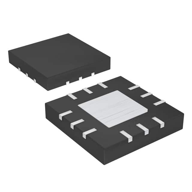
- Part No.:
- MAX3806GTC+T
- Manufacturer:
- Analog Devices Inc./Maxim Integrated
- Category:
- Sensor and Detector Interfaces
- Package:
- 12-WFQFN Exposed Pad
- Datasheet:
-
 MAX3806GTC+T.pdf
- Description:
- IC AMP TRANSIMPEDANCE 12TQFN
- Quantity:
- Payment:

- Shipping:

Inventory:4,441
Please send an inquiry. Send us your inquiry, and we will respond immediately.
Product details
Overview
MAX3806GTC+T from Maxim Integrated is a single-channel, high-gain linear transimpedance preamplifier designed for optical distance measurement systems using AC-coupled photodiodes. It operates from a +5.0V supply, delivers 60kΩ or 30kΩ selectable transimpedance gain, supports input pulses as narrow as 30ns, maintains linearity up to 40μAP, and withstands overload currents up to 2mAP - enabling robust laser time-of-flight (ToF) receiver front-ends in portable and industrial LIDAR sensors.
For engineers reviewing the MAX3806GTC+T datasheet, MAX3806GTC+T pinout, MAX3806GTC+T application, or MAX3806GTC+T equivalent, this page provides verified functional context, validated pin roles, confirmed noise performance (1.5pA/√Hz at 60kΩ), real-world settling behavior, and direct alternative options for optical receiver design.
Technical Context
The MAX3806GTC+T integrates three configurable blocks: a CMOS/TTL-controlled transimpedance amplifier with two discrete gain settings (60kΩ or 30kΩ), a 14dB attenuator selected via the ATT pin, and an output driver with high-impedance disable capability controlled by the DIS pin. Its input stage accepts fast, low-amplitude photodiode current pulses without saturation, while its output is strictly AC-coupled to ≥2kΩ loads.
It features internal pull-up (60kΩ on DIS) and pull-down (40kΩ on GAIN/ATT) resistors, operates across –40°C to +105°C, and uses a thermally enhanced 3mm × 3mm 12-pin TQFN-EP package with soldered exposed pad for ground and thermal management. The device does not support DC-coupled output loading - doing so risks permanent damage.
Key Specifications
| Parameter | Value and Actual Design Meaning |
|---|---|
| Supply Voltage | +4.5V to +5.5V - ensures stable operation under typical LIDAR power rail tolerances; absolute max is +6.0V. |
| Transimpedance Gain | 60kΩ or 30kΩ - selected via GAIN pin; defines signal amplification ratio from photodiode current to output voltage. |
| Input-Referred Noise | 1.5pA/√Hz (TYP, 60kΩ gain) - sets minimum detectable photocurrent level in low-light ToF applications. |
| Small-Signal Bandwidth | 49MHz (GAIN=1, ATT=0) - supports pulse widths down to ~30ns with minimal rise-time degradation. |
| Overload Current Handling | 2mAP - enables reliable recovery after strong ambient light or reflective surface spikes without latch-up. |
| Power Dissipation | 50mW (TYP at +5V) - allows compact placement near photodiode without thermal derating in handheld units. |
| Operating Temperature | –40°C to +105°C - qualified for industrial and outdoor portable distance measurement environments. |
Pinout & Package
The MAX3806GTC+T is housed in a 3mm × 3mm, 12-pin thin quad flat no-lead package with exposed pad (TQFN-EP), requiring soldering of the EP pad to PCB ground for thermal integrity and electrical reference.
| Pin/Terminal | Circuit Role | Design Meaning |
|---|---|---|
| 1, 12 | VCC | +5V power supply connection; decoupling capacitor required per pin for noise suppression. |
| 2 | IN | AC-coupled photodiode current input; sensitive to stray capacitance - must minimize trace length and ground plane proximity. |
| 3, 4 | GND | Analog ground reference; tied internally to exposed pad - must connect EP to same ground plane. |
| 5 | ATT | CMOS/TTL input; high = enable 14dB attenuation, low = bypass; internal 40kΩ pulldown resistor. |
| 6, 8, 11 | N.C. | No internal connection - leave unconnected and unstubbed on PCB. |
| 7 | GAIN | CMOS/TTL input; high = 60kΩ transimpedance, low = 30kΩ; internal 40kΩ pulldown resistor. |
| 9 | OUT | Single-ended voltage output; must be AC-coupled to ≥2kΩ load - DC coupling may damage output stage. |
| 10 | DIS | CMOS/TTL input; high = disable output (high-Z), low = enable; internal 60kΩ pullup resistor. |
Key Features
| Feature | Design Value |
|---|---|
| Selectable transimpedance gain | 60kΩ or 30kΩ - matches dynamic range requirements of different photodiode sizes and optical paths. |
| Configurable 14dB attenuation | Enables signal scaling before ADC digitization, preventing clipping in high-signal conditions. |
| Output disable with <200ns settling | Allows precise blanking during laser pulse transmission or inter-channel multiplexing in multi-receiver arrays. |
| Low input-referred noise density | 1.5pA/√Hz at 60kΩ gain - preserves SNR for weak return signals in long-range or low-power LIDAR. |
| Overload resilience | Withstands 2mAP input without damage or sustained distortion - critical for outdoor or high-reflectivity use cases. |
Applications
| Laser Distance Meter (Handheld) | Industrial LIDAR Sensor |
|---|---|
|
Use Scenario: Portable laser tape measure used in construction and surveying, operating indoors and outdoors with variable ambient light. IC Role / Device Role / Timing Role: Linear preamplifier converting nanosecond-scale photodiode current pulses into clean voltage signals for time-of-flight calculation. Use Value: 30ns pulse support and 2mAP overload tolerance ensure reliable ranging even under glare or reflective surfaces. |
Use Scenario: Fixed-mount LIDAR for object detection and position feedback in automated guided vehicles (AGVs) and robotic arms. IC Role / Device Role / Timing Role: High-speed, temperature-stable receiver front-end in multi-channel optical sensing modules. Use Value: –40°C to +105°C operation and 49MHz bandwidth maintain timing accuracy across factory floor thermal gradients. |
| Smartphone Depth Sensing Module | Automated Door Safety Scanner |
|
Use Scenario: Compact VCSEL-based time-of-flight depth camera in consumer electronics for facial recognition and AR. IC Role / Device Role / Timing Role: Low-noise, space-constrained analog front-end for short-range (<1m), high-frame-rate depth acquisition. Use Value: 1.5pA/√Hz noise density and 50mW power dissipation enable high-resolution depth maps without thermal throttling. |
Use Scenario: Safety-rated optical curtain for automatic doors in commercial buildings, detecting intrusion within 10cm–2m range. IC Role / Device Role / Timing Role: Fast-response receiver that triggers immediate door stop/reverse upon beam interruption. Use Value: Sub-50ns output enable/disable settling supports real-time safety logic with deterministic latency. |
Equivalent & Alternatives
The following parts are listed as comparable options for similar transimpedance amplifier applications.
| Alternative Part | Technical Difference | Application Difference | Selection Advice |
|---|---|---|---|
| MAX3805GTC+ | Single-supply +5V, 40kΩ fixed gain, no ATT/DIS pins, 35MHz bandwidth, higher input noise (2.3pA/√Hz). | Lacks programmability - suited only for static gain, lower-bandwidth, cost-sensitive designs. | Choose when gain and attenuation control are unnecessary and board space is constrained. |
| LMH6629MA/NOPB | Wideband current-feedback op-amp (1.5GHz GBW), requires external transimpedance resistor, no integrated ATT/DIS logic. | Demands custom layout, external components, and active biasing - increases BOM and validation effort. | Choose only when >100MHz bandwidth or ultra-low input capacitance (<0.5pF) is mandatory. |
Compared with MAX3805GTC+, the MAX3806GTC+ adds programmable gain and attenuation for adaptive signal conditioning; compared with LMH6629MA/NOPB, it integrates configuration logic and reduces system-level complexity at the cost of fixed bandwidth limits.
Availability
MAX3806GTC+T is available at Aetrix Electronics and suitable for laser distance meters, industrial LIDAR sensors, and optical safety scanners requiring stable component supply, extended temperature qualification, and RoHS-compliant packaging.
Supply support for MAX3806GTC+T includes scheduled delivery planning, volume procurement assistance, BOM continuity management, traceable sourcing, and lifecycle availability coordination for OEM customers, industrial embedded developers, connected-device designers, and electronics production programs.
Manufacturer
Maxim Integrated (now part of Analog Devices) designs precision analog, mixed-signal, and power management ICs for demanding industrial, medical, and communications applications.
The MAX3806GTC+T belongs to Maxim's optical receiver front-end product line, engineered specifically for high-speed, low-noise amplification of photodiode current in time-of-flight distance measurement systems.
FAQ
What is the maximum input pulse width the MAX3806GTC+T can handle linearly?
The MAX3806GTC+T does not specify a maximum pulse width for linear operation - its linearity is defined by input amplitude, not duration. It remains linear for input currents from 42nAP (SNR = 3) up to 40μAP, regardless of pulse width, provided the signal stays within its small-signal bandwidth (up to 49MHz at 60kΩ gain). Pulse widths from 30ns to continuous CW are supported within these amplitude limits.
Can the MAX3806GTC+T output be DC-coupled to a 1kΩ load?
No - the MAX3806GTC+T output stage is explicitly designed for AC-coupled operation to loads ≥2kΩ. DC-coupling the output to a 1kΩ or lower impedance load violates the Absolute Maximum Ratings and may permanently damage the output driver. The datasheet warns: "Operating the part with its output DC-coupled to GND through a 2kΩ or less load may damage the output." Always use a series DC-blocking capacitor (e.g., 0.01µF) and verify load impedance.
How does the DIS pin affect settling time in the MAX3806GTC+T?
When the DIS pin is asserted high, the MAX3806GTC+T output enters high-impedance state and settles to steady state within 200ns. When DIS is deasserted (driven low), the output re-enables and settles within 50ns. These values are independent of RC time constants associated with gain or attenuation switching - DIS control provides deterministic, sub-200ns blanking for time-critical optical gating or channel multiplexing.
What is the role of the exposed pad (EP) on the MAX3806GTC+T package?
The exposed pad (EP) on the MAX3806GTC+T serves dual functions: it provides a low-thermal-resistance path for heat dissipation and acts as the internal analog ground connection. Per the datasheet, the EP must be soldered directly to the PCB ground plane to ensure proper thermal performance and electrical reference stability. Failure to do so risks degraded noise performance, bandwidth reduction, and potential thermal shutdown under sustained operation.
Does the MAX3806GTC+T support differential output or require external components for common-mode rejection?
No - the MAX3806GTC+T provides a single-ended output only and does not include differential output capability or built-in common-mode rejection circuitry. Its output is referenced to VCC/2 (e.g., 1.65V common-mode voltage at GAIN=0, ATT=0), and common-mode rejection relies entirely on downstream stages (e.g., ADC input buffer or external differential amplifier). No external components are required for basic operation, but system-level CMRR depends on external design choices.
MAX3806GTC+T Specifications
- Product attributes
- Attribute value
- Manufacturer:
- Analog Devices Inc./Maxim Integrated
- Package/Case:
- 12-WFQFN Exposed Pad
- Series:
- -
- Packaging:
- Tape & Reel (TR)
- Product Status:
- Active
- Programmable:
- Not Verified
- Type:
- Distance Measuring, Preamplifier
- Input Type:
- Logic
- Output Type:
- Voltage
- Current - Supply:
- 15 mA
- Operating Temperature:
- -40°C ~ 105°C
- Grade:
- -
- Qualification:
- -
- Mounting Type:
- Surface Mount
- Supplier Device Package:
- 12-TQFN (3x3)
MAX3806GTC+T FAQ
1.How can I place an order for MAX3806GTC+T through Aetrix?
Please submit a Request for Quotation (RFQ) for MAX3806GTC+T on Aetrix. Our sales agent will provide a competitive quotation and guide you through the order confirmation once you accept the terms.
2.Are the price and stock information for MAX3806GTC+T reliable?
The price and inventory of MAX3806GTC+T are updated periodically and may fluctuate due to market conditions. Stock and pricing data are typically refreshed every 24 hours. Quotation validity for MAX3806GTC+T is usually 5 days.
3.What payment methods are accepted for MAX3806GTC+T?
We accept Wire Transfer, PayPal, Credit Card, Western Union, MoneyGram, and Escrow for MAX3806GTC+T transactions.
Note: Certain payment methods may incur a processing fee.
4.How is shipping managed for MAX3806GTC+T?
MAX3806GTC+T orders can be shipped via leading logistics carriers, including DHL, UPS, FedEx, TNT, or Registered Mail.
Once your MAX3806GTC+T order is processed, you will receive an email with the shipment details and tracking number.
Note: Tracking information may take up to 24 hours to appear. Express delivery typically takes 3–5 business days.
5.How can I obtain technical support or documentation for MAX3806GTC+T?
For technical support, including MAX3806GTC+T datasheets, pinout diagrams, or application guidance, please contact our engineering support team. They can provide detailed documentation and assistance for your MAX3806GTC+T requirements.
6.How does Aetrix verify that MAX3806GTC+T is sourced from the original manufacturer or authorized distributors?
All MAX3806GTC+T products on Aetrix are procured from qualified distributors and authorized channels. Our dedicated quality assurance team conducts strict verification, including traceability checks and, if necessary, third-party testing. This ensures that MAX3806GTC+T meets industry standards.
7.What is the process for return or replacement of MAX3806GTC+T?
All MAX3806GTC+T units undergo pre-shipment inspection (PSI). If there is an issue with MAX3806GTC+T, returns or replacements are accepted under the following conditions:
1.Quantity discrepancies, incorrect items, or visible external defects (such as breakage or corrosion), acknowledged by Aetrix.
2.The issue is reported within 90 days of delivery.
3.The MAX3806GTC+T part is unused and in its original packaging.
Return procedure for MAX3806GTC+T:
1.Submit a request within 90 days.
2.Obtain a Return Material Authorization (RMA) from Aetrix.
MAX3806GTC+T Tags

-
RE46C100S8TF
Microchip Technology

-
XTR111AIDRCR
Texas Instruments

-
XTR111AIDGQR
Texas Instruments

-
XTR117AIDGKR
Texas Instruments
-
XTR111AIDGQT
Texas Instruments

-
XTR115UA/2K5
Texas Instruments

-
MAX14626ETT+T
Analog Devices Inc./Maxim Integrated
-
XTR116UA/2K5
Texas Instruments
-
XTR115U/2K5
Texas Instruments
-
XTR116U/2K5
Texas Instruments

-
PGA308AIDGSR
Texas Instruments

-
XTR300AIRGWR
Texas Instruments
Tech Hub

A practical engineering guide to 3.3V and 5V logic compatibility, input thresholds, resistor dividers, translator ICs, MOSFET level shifting, I2C pull-ups, timing limits and power-sequencing risks.

The 74HC595 uses push-pull logic outputs, while the TPIC6B595 uses 50 V open-drain DMOS sinks for higher-power loads. This guide compares timing, current limits, 3.3 V interfacing, load wiring, thermal…

The 74HC595 converts serial data into eight stable parallel outputs. This guide covers pin functions, shift and storage timing, OE and MR behavior, drive-current limits, cascading, voltage compatibilit…

A technical comparison of level-sensitive latches and edge-triggered flip-flops, covering timing windows, setup and hold limits, master–slave operation, time borrowing, race-through, HDL inference and…

A D latch stores one bit while Enable controls when data can pass. This reference covers gate-level operation, truth tables, transparency, setup and hold timing, LE versus OE, common ICs and practical …

An SR latch stores one bit through cross-coupled feedback. This engineering reference covers NOR and NAND implementations, truth tables, forbidden-state recovery, gated operation, switch debouncing, fa…

Latch circuits retain one bit through feedback. This technical reference covers SR and D latches, truth tables, transparency, timing limits, latch-versus-flip-flop behavior, applications and common log…

An engineering guide to LED driver operation, constant-current and constant-voltage outputs, linear and switching topologies, dimming, IC selection, calculations, replacement compatibility, and fault c…

Operational amplifier guide covering op amp basics, feedback, ideal vs real op amps, common configurations, buffer circuits, offset, bias current, gain-bandwidth, slew rate, rail-to-rail limits and sel…

Jumper cables guide covering safe connection order, red and black clamp placement, final ground connection, cable gauge, length, clamp quality, copper vs CCA cables, jump starter comparison and battery…


