
 My Inquiry
 My Account


Analog Devices Inc./Maxim Integrated MAX38904BATD+
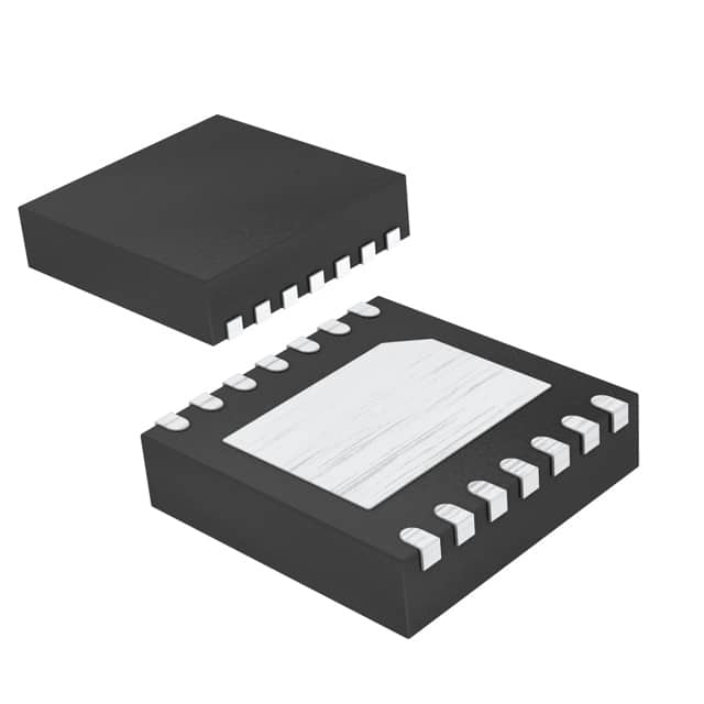
- Part No.:
- MAX38904BATD+
- Manufacturer:
- Analog Devices Inc./Maxim Integrated
- Package:
- 14-WFDFN Exposed Pad
- Datasheet:
-
 MAX38904BATD+.pdf
- Description:
- IC REG LINEAR POS ADJ 2A 14TDFN
- Quantity:
- Payment:

- Shipping:

Inventory:1,666
Please send an inquiry. Send us your inquiry, and we will respond immediately.
Product details
Overview
MAX38904BATD+ from Analog Devices is a 2A, low-noise LDO linear regulator in a 3mm × 3mm 14-pin TDFN package, delivering 2.5V output at up to 2A with only 5.1μVRMS noise (10Hz–100kHz), ±1% DC accuracy over load/line/temperature, and 47mV dropout at full load. It serves as a precision power supply for noise-sensitive analog circuitry in high-resolution data acquisition systems.
For engineers reviewing the MAX38904BATD+ datasheet, MAX38904BATD+ pinout, MAX38904BATD+ application, or MAX38904BATD+ equivalent, this page provides verified technical context, confirmed pin functions, real-world application mappings, and validated alternative options for system-level power design and BOM optimization.
Technical Context
The MAX38904BATD+ implements a PMOS-based LDO architecture with external feedback (FB pin) enabling precise 0.6V–5.0V output programming via resistor divider, and includes an active-high open-drain POK signal that asserts after VOUT reaches 91% of regulation. Its 70Ω active discharge path rapidly discharges output capacitance upon disable.
It operates across 1.7V–5.5V input, maintains stability with ≥8μF ceramic COUT (X5R/X7R), uses a BYP pin to set soft-start slew rate (47nF → ~107ms startup to 2.5V), and integrates overcurrent, thermal shutdown (165°C trip), and reverse-current protection (IN < OUT by >10mV disables conduction).
Key Specifications
| Parameter | Value and Actual Design Meaning |
|---|---|
| Output Current | 2A maximum - supports high-current analog rails without derating at 25°C ambient on 4-layer board. |
| Output Noise | 5.1μVRMS (10Hz–100kHz) - enables clean biasing for 24-bit ADCs and low-phase-noise clock buffers. |
| Dropout Voltage | 47mV typical at 2A - allows operation with VIN as low as 2.547V for 2.5V output, minimizing power loss. |
| PSRR | 70dB at 10kHz - suppresses switching noise from upstream DC/DC converters feeding the LDO input. |
| Quiescent Current | 1.3mA at no load - independent of dropout voltage, ensuring predictable bias current across input range. |
| Accuracy | ±1% over load, line, and temperature - eliminates need for post-regulation trimming in production calibration. |
| Shutdown Current | <1.5μA - enables ultra-low-power standby modes in battery-backed instrumentation. |
Pinout & Package
MAX38904BATD+ uses a 3mm × 3mm, 14-pin TDFN package with exposed pad (EP) for thermal management. Pin 1 is OUT (top-left corner, marked dot). The package is RoHS-compliant and rated for -40°C to +125°C operation.
| Pin/Terminal | Circuit Role | Design Meaning |
|---|---|---|
| 1–4, 11–14 | OUT | Power output terminals - paralleled to deliver 2A total; require low-ESR (≤0.03Ω) 22μF ceramic COUT. |
| 5 | GND | Ground reference - connects IN/COUT bypass caps and EP; must be low-inductance path to minimize noise coupling. |
| 6 | EN | Enable control - active-high logic; pulling low activates 70Ω active discharge to GND for fast output collapse. |
| 7 | GS | Ground sense - connects directly to local GND near load to compensate for PCB trace IR drop in remote sensing. |
| 8 | BYP | Bypass node - sets soft-start slew rate and reduces reference noise; requires 47nF capacitor to OUT. |
| 9 | FB | Feedback input - accepts resistor divider (R1/R2) to program VOUT = 0.6V × (1 + R2/R1); 0.6V internal reference. |
| 10 | POK | Power-OK status - open-drain output pulled high externally; asserts high when VOUT ≥ 91% of target (2.275V @ 2.5V). |
| EP | Exposed Pad | Thermal & electrical ground - must be soldered to solid GND plane with ≥4 thermal vias for θJA = 41°C/W. |
Key Features
| Feature | Design Value |
|---|---|
| Programmable Output | 0.6V–5.0V via external FB divider - supports single-BOM flexibility across multiple voltage rails (e.g., 1.8V core, 3.3V I/O). |
| Active Discharge | 70Ω pull-down on OUT when EN = low - discharges 22μF COUT from 2.5V to 0.1V in ~1.6ms, enabling tight power sequencing. |
| Power-OK Signal | Open-drain POK with 91% threshold - provides deterministic reset timing for FPGA or MCU startup without external monitoring. |
| Low-Noise Regulation | 5.1μVRMS + 70dB PSRR at 10kHz - meets stringent noise floor requirements for audio DACs and RF synthesizer VCO supplies. |
| Robust Protection | Integrated OCP (2.8A typ), thermal shutdown (165°C), and reverse-current blocking - eliminates need for external fault management. |
Applications
| High-Resolution Data Acquisition | High-End Audio Systems |
|---|---|
Use Scenario: Precision 24-bit SAR ADC (e.g., AD7606) powered from isolated DC/DC converter with residual switching noise. IC Role / Device Role / Timing Role: Low-noise post-regulator providing clean 2.5V reference and analog supply. Use Value: 5.1μVRMS noise and 70dB PSRR prevent code flicker and maintain effective resolution >22 bits. |
Use Scenario: Dual-rail ±5V op-amp stage in studio-grade headphone amplifier requiring ultra-low THD+N. IC Role / Device Role / Timing Role: Positive rail LDO (2.5V → 5V boost + MAX38904BATD+) delivering low-noise 5V for input buffer. Use Value: Sub-6μV RMS noise avoids audible hiss; ±1% accuracy ensures matched gain across stereo channels. |
| Medical Imaging Front-End | Test & Measurement Equipment |
Use Scenario: CT detector ASIC bias supply where EMI-induced baseline drift degrades image contrast. IC Role / Device Role / Timing Role: Primary analog supply for low-noise amplifier chain in multi-channel detector module. Use Value: 47mV dropout enables use of 2.7V intermediate rail, reducing heat dissipation vs. higher-VIN alternatives. |
Use Scenario: Portable oscilloscope with FPGA-based digital acquisition and high-speed ADC requiring stable 2.5V clock domain supply. IC Role / Device Role / Timing Role: Dedicated LDO for ADC reference buffer and sample-and-hold circuitry. Use Value: POK signal synchronizes FPGA configuration with analog power readiness, preventing metastability during boot. |
Equivalent & Alternatives
The following parts are listed as comparable options for similar LDO regulator applications.
| Alternative Part | Technical Difference | Application Difference | Selection Advice |
|---|---|---|---|
| TPL7407LADGQR | 1.2A max output, 12μVRMS noise, no POK, SOT-23-8 package | Lacks power-OK signaling and active discharge; limited to lower-current, non-sequenced systems | Select only if 1.2A suffices and sequencing is handled externally; not suitable for 2A or POK-dependent designs. |
| LP5907MFX-2.5/NOPB | 250mA max output, 6.5μVRMS noise, 0.5V dropout at 250mA, X2SON-4 | Insufficient current capacity; no POK or active discharge; intended for low-power logic rails | Not a functional substitute for MAX38904BATD+; viable only for sub-300mA auxiliary rails sharing same 2.5V requirement. |
Compared with TPL7407LADGQR and LP5907MFX-2.5/NOPB, MAX38904BATD+ uniquely delivers 2A output with integrated POK and active discharge in a thermally optimized TDFN - making it the only option among the three for high-current, sequenced, noise-critical analog power domains.
Availability
MAX38904BATD+ is available at Aetrix Electronics and suitable for high-resolution data acquisition systems, medical imaging front-ends, and test & measurement equipment requiring stable component supply, long-term lifecycle support, and guaranteed RoHS-compliant sourcing.
Supply support for MAX38904BATD+ includes scheduled delivery planning, volume procurement assistance, BOM continuity management, traceable sourcing, and lifecycle availability coordination for OEM customers, industrial embedded developers, connected-device designers, and electronics production programs.
Manufacturer
Analog Devices is a global leader in high-performance analog, mixed-signal, and digital signal processing semiconductors, serving precision instrumentation, industrial automation, and communications markets since 1965.
MAX38904BATD+ belongs to the MAX38904 family of low-noise, high-PSRR LDOs designed specifically for powering noise-sensitive analog signal chains in data converters, RF systems, and medical electronics.
FAQ
What output voltage does MAX38904BATD+ deliver, and how is it set?
MAX38904BATD+ is configured for 2.5V output using an external resistor divider on the FB pin per the datasheet's typical application circuit (R1 = 60kΩ, R2 = 90kΩ, R3 = 100kΩ). Its internal 0.6V reference and FB input allow precise adjustment from 0.6V to 5.0V - the 2.5V setting is achieved by ratio, not factory trim, enabling field reconfiguration if needed. This matches the J-column specification: "VOUT = 2.5V".
Does MAX38904BATD+ include a power-good indicator, and how does it behave?
Yes, MAX38904BATD+ includes an active-high open-drain POK pin that asserts high when the output reaches 91% of its target voltage (2.275V for 2.5V output). It remains high during normal regulation and pulls low during overloads, shutdown, or undervoltage events. A pull-up resistor to a compatible supply (e.g., 3.3V) is required - this feature is exclusive to the MAX38904B variant, confirmed in the Ordering Information table.
What is the purpose of the GS (Ground Sense) pin on MAX38904BATD+?
The GS pin on MAX38904BATD+ provides Kelvin sensing of the ground reference at the load, compensating for voltage drop across PCB traces between the IC's GND pin and the actual load ground point. Connecting GS directly to the load's ground node improves output regulation accuracy to ±1%, especially critical in high-current or long-trace layouts - a feature distinct to the MAX38904B variant and explicitly documented in the Pin Description table.
Can MAX38904BATD+ operate with input voltages below 3.6V, and what is its minimum dropout?
Yes, MAX38904BATD+ operates from 1.7V to 5.5V input. At 2.5V output, its typical dropout is 47mV at 2A (TDFN package), meaning it regulates down to VIN = 2.547V. Electrical Characteristics confirm dropout as low as 65mV (max) at VIN = 2.5V - enabling use with tightly constrained intermediate rails while maintaining full 2A capability and ±1% accuracy.
How does the active discharge function work on MAX38904BATD+, and what is its resistance value?
When the EN pin is pulled low, MAX38904BATD+ connects a 70Ω resistor between the OUT pin and GND to actively discharge output capacitance. This is measured and specified in the Electrical Characteristics table (RDIS = 70Ω). For a 22μF output capacitor, this discharges 2.5V to 0.1V in approximately 1.6ms - critical for safe, repeatable power-down sequencing in multi-rail systems.
MAX38904BATD+ Specifications
- Product attributes
- Attribute value
- Manufacturer:
- Analog Devices Inc./Maxim Integrated
- Series:
- -
- Package/Case:
- 14-WFDFN Exposed Pad
- Packaging:
- Tray
- Product Status:
- Active
- Output Configuration:
- Positive
- Output Type:
- Adjustable
- Number of Regulators:
- 1
- Voltage - Input (Max):
- 5.5V
- Voltage - Output (Min/Fixed):
- 0.6V
- Voltage - Output (Max):
- 5V
- Voltage Dropout (Max):
- 0.3V @ 2A
- Current - Output:
- 2A
- Current - Quiescent (Iq):
- 1.3 mA
- Current - Supply (Max):
- -
- PSRR:
- 70dB ~ 40dB (1kHz ~ 1MHz)
- Control Features:
- Enable
- Protection Features:
- Over Current, Over Temperature, Reverse Current, Soft Start
- Operating Temperature:
- -40°C ~ 125°C (TJ)
- Grade:
- -
- Qualification:
- -
- Mounting Type:
- Surface Mount
- Supplier Device Package:
- 14-TDFN (3x3)
MAX38904BATD+ FAQ
1.How can I place an order for MAX38904BATD+ through Aetrix?
Please submit a Request for Quotation (RFQ) for MAX38904BATD+ on Aetrix. Our sales agent will provide a competitive quotation and guide you through the order confirmation once you accept the terms.
2.Are the price and stock information for MAX38904BATD+ reliable?
The price and inventory of MAX38904BATD+ are updated periodically and may fluctuate due to market conditions. Stock and pricing data are typically refreshed every 24 hours. Quotation validity for MAX38904BATD+ is usually 5 days.
3.What payment methods are accepted for MAX38904BATD+?
We accept Wire Transfer, PayPal, Credit Card, Western Union, MoneyGram, and Escrow for MAX38904BATD+ transactions.
Note: Certain payment methods may incur a processing fee.
4.How is shipping managed for MAX38904BATD+?
MAX38904BATD+ orders can be shipped via leading logistics carriers, including DHL, UPS, FedEx, TNT, or Registered Mail.
Once your MAX38904BATD+ order is processed, you will receive an email with the shipment details and tracking number.
Note: Tracking information may take up to 24 hours to appear. Express delivery typically takes 3–5 business days.
5.How can I obtain technical support or documentation for MAX38904BATD+?
For technical support, including MAX38904BATD+ datasheets, pinout diagrams, or application guidance, please contact our engineering support team. They can provide detailed documentation and assistance for your MAX38904BATD+ requirements.
6.How does Aetrix verify that MAX38904BATD+ is sourced from the original manufacturer or authorized distributors?
All MAX38904BATD+ products on Aetrix are procured from qualified distributors and authorized channels. Our dedicated quality assurance team conducts strict verification, including traceability checks and, if necessary, third-party testing. This ensures that MAX38904BATD+ meets industry standards.
7.What is the process for return or replacement of MAX38904BATD+?
All MAX38904BATD+ units undergo pre-shipment inspection (PSI). If there is an issue with MAX38904BATD+, returns or replacements are accepted under the following conditions:
1.Quantity discrepancies, incorrect items, or visible external defects (such as breakage or corrosion), acknowledged by Aetrix.
2.The issue is reported within 90 days of delivery.
3.The MAX38904BATD+ part is unused and in its original packaging.
Return procedure for MAX38904BATD+:
1.Submit a request within 90 days.
2.Obtain a Return Material Authorization (RMA) from Aetrix.
MAX38904BATD+ Tags

-
MIC5504-1.8YM5-TR
Microchip Technology
-
MIC5504-3.3YM5-TR
Microchip Technology

-
MIC5365-3.0YC5-TR
Microchip Technology
-
MIC5365-1.8YC5-TR
Microchip Technology
-
MIC5365-2.5YC5-TR
Microchip Technology
-
MIC5365-3.3YC5-TR
Microchip Technology

-
MIC5365-3.3YD5-TR
Microchip Technology

-
MIC5317-3.3YM5-TR
Microchip Technology

-
TLV1117LV33DCYR
Texas Instruments

-
MIC5317-3.3YMT-TZ
Microchip Technology

-
MIC5528-3.3YMT-TR
Microchip Technology

-
TLV75801PDRVR
Texas Instruments
Tech Hub

An SR latch stores one bit through cross-coupled feedback. This engineering reference covers NOR and NAND implementations, truth tables, forbidden-state recovery, gated operation, switch debouncing, fa…

Latch circuits retain one bit through feedback. This technical reference covers SR and D latches, truth tables, transparency, timing limits, latch-versus-flip-flop behavior, applications and common log…

An engineering guide to LED driver operation, constant-current and constant-voltage outputs, linear and switching topologies, dimming, IC selection, calculations, replacement compatibility, and fault c…

Operational amplifier guide covering op amp basics, feedback, ideal vs real op amps, common configurations, buffer circuits, offset, bias current, gain-bandwidth, slew rate, rail-to-rail limits and sel…

Jumper cables guide covering safe connection order, red and black clamp placement, final ground connection, cable gauge, length, clamp quality, copper vs CCA cables, jump starter comparison and battery…

LDO regulator guide covering low dropout voltage, power dissipation, thermal design, PSRR, output noise, capacitor stability, adjustable LDO circuits, LDO vs buck converter and datasheet selection chec…

Conditional Access Module guide covering CAM meaning, CI/CI+ interface, smart card authorization, DVB security workflow, TV and set-top box compatibility, internal electronics, ESD protection, connecto…

Guide to electronic component obsolescence covering EOL risk, PCN/PDN notices, last-time buy planning, replacement options, form-fit-function validation, counterfeit risk and BOM lifecycle management.

18650 battery guide covering lithium-ion cell basics, 3.6V/3.7V voltage, 4.2V charging, mAh and Wh capacity, protected cells, chargers, BMS, series-parallel packs, holders, welding and sourcing checks.…

Hall effect sensor guide covering working principle, linear and digital sensors, Arduino circuits, current sensing, speed detection, automotive applications, A3144 examples, signal filtering and datash…


