
 My Inquiry
 My Account


Analog Devices Inc./Maxim Integrated MAX38908ATD+T
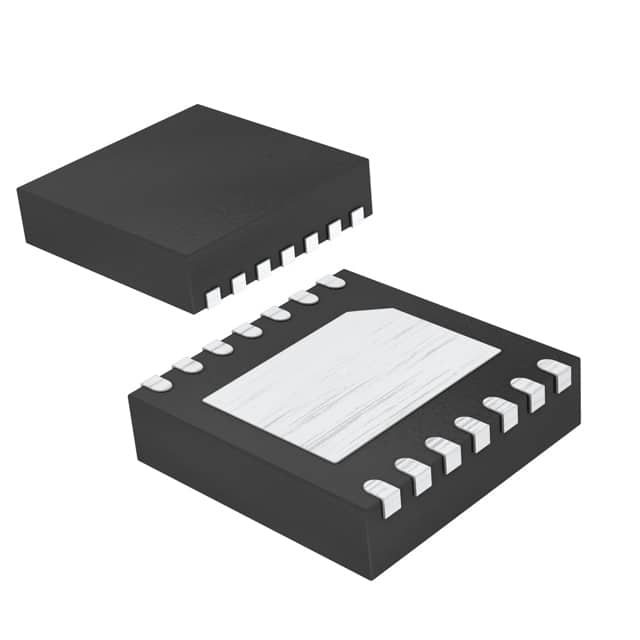
- Part No.:
- MAX38908ATD+T
- Manufacturer:
- Analog Devices Inc./Maxim Integrated
- Package:
- 14-WFDFN Exposed Pad
- Datasheet:
-
 MAX38908ATD+T.pdf
- Description:
- IC REG LINEAR POS ADJ 4A 14TDFN
- Quantity:
- Payment:

- Shipping:

Inventory:4,135
Please send an inquiry. Send us your inquiry, and we will respond immediately.
Product details
Overview
MAX38908ATD+T from Maxim Integrated is a 4A, high-PSRR nMOS LDO linear regulator with adjustable 0.6V–5.0V output, 0.9V–5.5V input range, and 2.7V–20V BIAS supply support-designed for FPGA core rails, server μPs, and portable cameras requiring tight ±1% DC accuracy and fast transient response under 4A load.
For engineers reviewing the MAX38908ATD+T datasheet, MAX38908ATD+T pinout, MAX38908ATD+T application, or MAX38908ATD+T equivalent, this page delivers verified package mapping (14-pin 3mm×3mm TDFN), confirmed feedback-based voltage programming, thermal shutdown at 165°C, 52dB IN PSRR at 10kHz, and reverse-current protection-key selection criteria for high-reliability power delivery in space-constrained embedded systems.
Technical Context
The MAX38908ATD+T uses an nMOS pass device architecture with separate BIAS rail to decouple gate drive from input supply, enabling stable operation across wide VIN (0.9V–5.5V) and VBIAS (2.7V–20V) ranges while maintaining low dropout (79mV typ at 4A, VOUT=1.2V, VBIAS=5V). Its feedback-controlled loop supports external resistor-divider programming and integrates active discharge, programmable soft-start via BYP capacitor, and monotonic startup.
Protection circuitry includes overcurrent limiting (4.4A–6.8A trip), thermal shutdown (165°C rising / 150°C falling), output-to-input reverse-current blocking (triggered at ~0.7A), and dual UVLO (VIN: 0.45V typ, VBIAS: 2.55V typ) with hysteresis-ensuring robustness during brownouts, short circuits, and power sequencing events in industrial and computing applications.
Key Specifications
| Parameter | Value and Actual Design Meaning |
|---|---|
| Output Current | Up to 4A continuous-supports high-power FPGA cores and multi-core μPs without external current boosting. |
| Output Voltage Range | 0.6V to 5.0V, set by external FB resistor divider-enables single-BOM reuse across multiple voltage rails (e.g., 0.85V CPU core, 1.8V I/O, 3.3V peripheral). |
| Input Voltage Range | 0.9V to 5.5V-compatible with Li-ion, USB PD, and intermediate bus supplies; operates down to sub-1V for ultra-low-voltage SoCs. |
| BIAS Supply Range | 2.7V to 20V-decouples gate drive from input, enabling high efficiency and stability even when VIN drops near VOUT. |
| DC Accuracy | ±1% over line, load, and temperature (−40°C to +125°C)-guarantees reliable logic-level compliance for sensitive digital loads. |
| Dropout Voltage | 79mV typical at 4A, VOUT=1.2V, VBIAS=5V-minimizes power loss and heat generation in thermally constrained layouts. |
| IN PSRR @ 10kHz | 52dB at 300mV headroom-suppresses switching noise from upstream DC/DC converters feeding the LDO input. |
| Thermal Shutdown | 165°C junction temperature with 15°C hysteresis-prevents permanent damage during sustained overload or poor PCB thermal design. |
Pinout & Package
MAX38908ATD+T is housed in a 14-pin, 3mm × 3mm TDFN package (package code T1433+2C) with exposed pad for thermal dissipation. The package supports JEDEC-standard reflow and achieves θJA = 41°C/W on a four-layer board.
| Pin/Terminal | Circuit Role | Design Meaning |
|---|---|---|
| 1, 2, 3, 4 | IN | Primary input supply (0.9V–5.5V); bypassed with ≥22μF ceramic capacitor to GND for stability and transient response. |
| 5 | BIAS | Bias rail input (2.7V–20V); powers gate driver independently-must be ≥2V above target VOUT for full performance. |
| 6, 7 | GND | Power ground; connects IN/OUT bypass caps and provides low-impedance return path for high-frequency currents. |
| 8 | EN | Active-high enable; logic threshold VIH = 1.0V min, VIL = 0.9V max-connect to BIAS for always-on operation. |
| 9 | FB | Feedback input; connects center of resistor divider between OUT and GND to set output voltage per VFB = 0.6V ±1%. |
| 10 | POK | Open-drain Power-OK signal; asserts high when VOUT reaches 88–94% of target-used for system power sequencing. |
| 11, 12, 13, 14 | OUT | Regulated output (0.6V–5.0V, up to 4A); pulled low via 70Ω internal resistor when disabled to prevent backfeeding. |
| EP | Exposed Pad | Thermal and electrical ground; must be soldered to large copper pour for θJA reduction and reliability under full load. |
Key Features
| Feature | Design Value |
|---|---|
| Programmable Soft-Start | Monotonic startup slew rate controlled by external BYP capacitor (1nF–100nF); prevents inrush into large output capacitors. |
| Reverse-Current Protection | Blocks >0.7A reverse current when VOUT > VIN by disconnecting body diode-eliminates need for external blocking diode. |
| Power-OK Status Pin | Open-drain POK with 88–94% VOUT threshold and 10–100kΩ pullup range-enables precise power sequencing with downstream logic. |
| High PSRR Architecture | 52dB IN PSRR at 10kHz and 78dB BIAS PSRR at 10kHz-rejects noise from noisy DC/DC sources and BIAS rails. |
| Robust Fault Protection | Integrated overcurrent (4.4–6.8A), thermal shutdown (165°C), and dual UVLO (VIN/VBIAS) with hysteresis-ensures safe operation during faults. |
| Stable with Low ESR Caps | Guaranteed stability with ≥10μF ceramic output capacitance-reduces bill-of-materials and PCB area vs. traditional LDOs. |
Applications
| FPGA Core Power Delivery | Server Microprocessor Rails |
|---|---|
Use Scenario: Powers 0.85V–1.2V core voltage of Xilinx Kintex or Intel Stratix FPGAs with dynamic current demand up to 4A. IC Role / Device Role / Timing Role: Primary low-noise, high-current LDO delivering tightly regulated core voltage with <28mV load-transient excursion. Use Value: Enables reliable FPGA configuration and operation under rapid load steps without violating core voltage tolerance (±3%). |
Use Scenario: Supplies 1.0V–1.8V I/O or cache rails for AMD EPYC or Intel Xeon processors in dense server modules. IC Role / Device Role / Timing Role: Secondary LDO providing clean, sequenced power after primary VRMs-monitored via POK for BIOS handoff. Use Value: Maintains ±1% accuracy across −40°C to +125°C ambient, ensuring timing margin integrity in thermally stressed rack environments. |
| Portable Camera Sensor Bias | Industrial PLC I/O Modules |
Use Scenario: Generates 2.8V or 3.3V analog bias for CMOS image sensors in battery-powered action or medical endoscopes. IC Role / Device Role / Timing Role: Low-noise, low-dropout regulator with 21.2μVRMS output noise-critical for minimizing sensor readout noise. Use Value: Delivers stable bias despite Li-ion voltage sag (3.6V→3.0V), avoiding image artifacts during video capture. |
Use Scenario: Powers isolated 5V or 3.3V logic rails in DIN-rail mounted PLCs with wide industrial input (12–24V DC). IC Role / Device Role / Timing Role: High-PSRR LDO rejecting conducted noise from motor drives and relay coils on shared 24V bus. Use Value: 52dB IN PSRR at 10kHz suppresses 100kHz switching noise from adjacent SMPS, preventing false logic transitions. |
Equivalent & Alternatives
The following parts are listed as comparable options for similar LDO regulator applications.
| Alternative Part | Technical Difference | Application Difference | Selection Advice |
|---|---|---|---|
| TPS7A8300RGRT | 4A, 0.8V–3.6V output, fixed or adjustable via resistor; requires ≥1.1V input headroom; no separate BIAS rail. | Lacks independent BIAS supply-less efficient at low VIN/VOUT differentials; lower PSRR (45dB @ 10kHz). | Choose when BIAS rail complexity is undesirable and input headroom ≥1.1V is guaranteed. |
| NCP1117ST50T3G | 1A max, fixed 5.0V output, TO-220/SOT-223; 1.2V dropout; no POK, no reverse-current protection. | Not suitable for 4A loads or precision sequencing; lacks key protections and noise rejection needed in modern digital systems. | Only consider for low-cost, low-current legacy designs where size, accuracy, and protection are secondary. |
Compared with TPS7A8300RGRT and NCP1117ST50T3G, the MAX38908ATD+T uniquely combines 4A capability, BIAS-rail independence for ultra-low dropout, ±1% accuracy over temperature, and integrated reverse-current blocking-making it optimal for next-generation compact, high-reliability power systems.
Availability
MAX38908ATD+T is available at Aetrix Electronics and suitable for FPGA core power delivery, server microprocessor rails, and portable camera sensor bias requiring stable component supply, long-term lifecycle support, and traceable sourcing.
Supply support for MAX38908ATD+T includes scheduled delivery planning, volume procurement assistance, BOM continuity management, traceable sourcing, and lifecycle availability coordination for OEM customers, industrial embedded developers, connected-device designers, and electronics production programs.
Manufacturer
Maxim Integrated (now part of Analog Devices) is a semiconductor leader specializing in high-performance analog, mixed-signal, and power management ICs for demanding industrial, computing, and communications applications.
The MAX38907/MAX38908 product line was designed specifically for high-current, low-noise, and thermally constrained power delivery in advanced digital systems-including FPGAs, μPs, and imaging sensors-where traditional LDOs fail to meet PSRR, accuracy, or protection requirements.
FAQ
What is the minimum output capacitance required for stability of the MAX38908ATD+T?
The MAX38908ATD+T is stable with a minimum 10μF ceramic output capacitor. The datasheet specifies 22μF as the recommended value for optimal transient response and PSRR performance. Using less than 10μF risks instability, especially under full 4A load, due to insufficient phase margin in the control loop. Always place the capacitor close to the OUT and GND pins with low-inductance layout.
Does the MAX38908ATD+T require a separate BIAS supply to operate?
Yes-the MAX38908ATD+T requires a valid BIAS supply between 2.7V and 20V applied to the BIAS pin. This rail powers the gate driver independently of the IN supply, enabling low dropout and stable regulation even when VIN approaches VOUT. Without BIAS, the device will not regulate; the BIAS voltage must also exceed the target VOUT by at least 2.0V for full specification compliance.
How does the POK (Power-OK) pin function on the MAX38908ATD+T?
The POK pin on the MAX38908ATD+T is an open-drain output that goes high when VOUT reaches 88–94% of its target voltage, indicating regulation. It requires an external 10–100kΩ pullup resistor to a logic-compatible supply. POK remains low during startup, dropout, or fault conditions-enabling precise power sequencing with FPGAs, μPs, or ASICs that monitor reset status before initialization.
Can the MAX38908ATD+T be used in parallel for higher current?
No-parallel operation of the MAX38908ATD+T is not supported or characterized. Its feedback architecture and lack of current-sharing features (e.g., current-sense outputs or master-slave sync) make unbalanced current distribution likely, risking thermal runaway or premature failure. For >4A needs, select a higher-current LDO or use a multiphase DC/DC solution instead.
What is the maximum allowable input-to-output voltage difference (headroom) for specified PSRR performance of the MAX38908ATD+T?
The MAX38908ATD+T delivers its specified 52dB IN PSRR at 10kHz only when the input-to-output headroom is maintained at 300mV. Below this, PSRR degrades significantly-e.g., at 150mV headroom, PSRR falls to ~42dB. Designers must ensure VIN ≥ VOUT + 0.3V during steady-state operation to meet noise-rejection requirements in sensitive analog or high-speed digital circuits.
MAX38908ATD+T Specifications
- Product attributes
- Attribute value
- Manufacturer:
- Analog Devices Inc./Maxim Integrated
- Series:
- -
- Package/Case:
- 14-WFDFN Exposed Pad
- Packaging:
- Tape & Reel (TR)
- Product Status:
- Active
- Output Configuration:
- Positive
- Output Type:
- Adjustable
- Number of Regulators:
- 1
- Voltage - Input (Max):
- 5.5V
- Voltage - Output (Min/Fixed):
- 0.6V
- Voltage - Output (Max):
- 5V
- Voltage Dropout (Max):
- 0.15V @ 4A
- Current - Output:
- 4A
- Current - Quiescent (Iq):
- 150 µA
- Current - Supply (Max):
- -
- PSRR:
- 60dB ~ 42dB (1kHz ~ 100kHz)
- Control Features:
- Enable, Power On Reset
- Protection Features:
- Over Current, Over Temperature, Reverse Current, Soft Start
- Operating Temperature:
- -40°C ~ 125°C (TJ)
- Grade:
- -
- Qualification:
- -
- Mounting Type:
- Surface Mount
- Supplier Device Package:
- 14-TDFN (3x3)
MAX38908ATD+T FAQ
1.How can I place an order for MAX38908ATD+T through Aetrix?
Please submit a Request for Quotation (RFQ) for MAX38908ATD+T on Aetrix. Our sales agent will provide a competitive quotation and guide you through the order confirmation once you accept the terms.
2.Are the price and stock information for MAX38908ATD+T reliable?
The price and inventory of MAX38908ATD+T are updated periodically and may fluctuate due to market conditions. Stock and pricing data are typically refreshed every 24 hours. Quotation validity for MAX38908ATD+T is usually 5 days.
3.What payment methods are accepted for MAX38908ATD+T?
We accept Wire Transfer, PayPal, Credit Card, Western Union, MoneyGram, and Escrow for MAX38908ATD+T transactions.
Note: Certain payment methods may incur a processing fee.
4.How is shipping managed for MAX38908ATD+T?
MAX38908ATD+T orders can be shipped via leading logistics carriers, including DHL, UPS, FedEx, TNT, or Registered Mail.
Once your MAX38908ATD+T order is processed, you will receive an email with the shipment details and tracking number.
Note: Tracking information may take up to 24 hours to appear. Express delivery typically takes 3–5 business days.
5.How can I obtain technical support or documentation for MAX38908ATD+T?
For technical support, including MAX38908ATD+T datasheets, pinout diagrams, or application guidance, please contact our engineering support team. They can provide detailed documentation and assistance for your MAX38908ATD+T requirements.
6.How does Aetrix verify that MAX38908ATD+T is sourced from the original manufacturer or authorized distributors?
All MAX38908ATD+T products on Aetrix are procured from qualified distributors and authorized channels. Our dedicated quality assurance team conducts strict verification, including traceability checks and, if necessary, third-party testing. This ensures that MAX38908ATD+T meets industry standards.
7.What is the process for return or replacement of MAX38908ATD+T?
All MAX38908ATD+T units undergo pre-shipment inspection (PSI). If there is an issue with MAX38908ATD+T, returns or replacements are accepted under the following conditions:
1.Quantity discrepancies, incorrect items, or visible external defects (such as breakage or corrosion), acknowledged by Aetrix.
2.The issue is reported within 90 days of delivery.
3.The MAX38908ATD+T part is unused and in its original packaging.
Return procedure for MAX38908ATD+T:
1.Submit a request within 90 days.
2.Obtain a Return Material Authorization (RMA) from Aetrix.
MAX38908ATD+T Tags

-
MIC5504-1.8YM5-TR
Microchip Technology
-
MIC5504-3.3YM5-TR
Microchip Technology

-
MIC5365-3.0YC5-TR
Microchip Technology
-
MIC5365-1.8YC5-TR
Microchip Technology
-
MIC5365-2.5YC5-TR
Microchip Technology
-
MIC5365-3.3YC5-TR
Microchip Technology

-
MIC5365-3.3YD5-TR
Microchip Technology

-
MIC5317-3.3YM5-TR
Microchip Technology

-
TLV1117LV33DCYR
Texas Instruments

-
MIC5317-3.3YMT-TZ
Microchip Technology

-
MIC5528-3.3YMT-TR
Microchip Technology

-
TLV75801PDRVR
Texas Instruments
Tech Hub
A D latch stores one bit while Enable controls when data can pass. This reference covers gate-level operation, truth tables, transparency, setup and hold timing, LE versus OE, common ICs and practical …

An SR latch stores one bit through cross-coupled feedback. This engineering reference covers NOR and NAND implementations, truth tables, forbidden-state recovery, gated operation, switch debouncing, fa…

Latch circuits retain one bit through feedback. This technical reference covers SR and D latches, truth tables, transparency, timing limits, latch-versus-flip-flop behavior, applications and common log…

An engineering guide to LED driver operation, constant-current and constant-voltage outputs, linear and switching topologies, dimming, IC selection, calculations, replacement compatibility, and fault c…

Operational amplifier guide covering op amp basics, feedback, ideal vs real op amps, common configurations, buffer circuits, offset, bias current, gain-bandwidth, slew rate, rail-to-rail limits and sel…

Jumper cables guide covering safe connection order, red and black clamp placement, final ground connection, cable gauge, length, clamp quality, copper vs CCA cables, jump starter comparison and battery…

LDO regulator guide covering low dropout voltage, power dissipation, thermal design, PSRR, output noise, capacitor stability, adjustable LDO circuits, LDO vs buck converter and datasheet selection chec…

Conditional Access Module guide covering CAM meaning, CI/CI+ interface, smart card authorization, DVB security workflow, TV and set-top box compatibility, internal electronics, ESD protection, connecto…

Guide to electronic component obsolescence covering EOL risk, PCN/PDN notices, last-time buy planning, replacement options, form-fit-function validation, counterfeit risk and BOM lifecycle management.

18650 battery guide covering lithium-ion cell basics, 3.6V/3.7V voltage, 4.2V charging, mAh and Wh capacity, protected cells, chargers, BMS, series-parallel packs, holders, welding and sourcing checks.…


