
 My Inquiry
 My Account


Analog Devices Inc./Maxim Integrated MAX474CSA
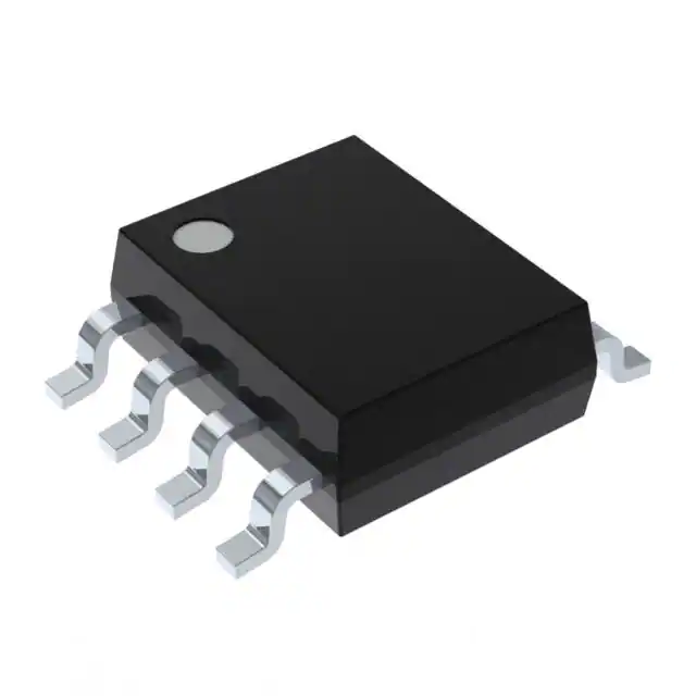
- Part No.:
- MAX474CSA
- Manufacturer:
- Analog Devices Inc./Maxim Integrated
- Category:
- Instrumentation, Op Amps, Buffer Amps
- Package:
- 8-SOIC (0.154", 3.90mm Width)
- Datasheet:
-
 MAX474CSA.pdf
- Description:
- IC OPAMP GP 2 CIRCUIT 8SOIC
- Quantity:
- Payment:

- Shipping:

Inventory:2,982
Please send an inquiry. Send us your inquiry, and we will respond immediately.
Product details
Overview
MAX474CSA from Maxim Integrated is a dual, single-supply operational amplifier with rail-to-rail output swing, 10MHz unity-gain bandwidth, 15V/µs slew rate, and 2mA per amplifier supply current. It operates from +2.7V to +5.25V, features input range extending to the negative rail, and delivers ±50mV rail-to-rail output swing - ideal for battery-powered signal conditioning in portable instrumentation.
For engineers reviewing the MAX474CSA datasheet, MAX474CSA pinout, MAX474CSA application, or MAX474CSA equivalent, key selection considerations include guaranteed 10MHz bandwidth at 3V supply, rail-to-rail output drive into 600Ω, input bias current under 175nA over temperature, short-circuit protected outputs, and SO-8 package compatibility with industry-standard op-amp footprints.
Technical Context
The MAX474CSA implements a bipolar input stage with output stage optimized for rail-to-rail swing down to VEE + 0.07V and up to VCC – 0.07V at 3V supply. Its unity-gain stability is confirmed across 10kΩ || 20pF loads with 63° phase margin, and it maintains 10MHz gain-bandwidth product from 2.7V to 5.25V supply.
Each amplifier guarantees 15V/µs minimum slew rate with 400ns settling time to 0.1%, supports common-mode input voltage from VEE to VCC – 1.9V, and provides 80dB PSRR and CMRR at DC - enabling precision DC-coupled amplification in low-voltage mixed-signal systems without dual supplies.
Key Specifications
| Parameter | Value and Actual Design Meaning |
|---|---|
| Supply Voltage Range | +2.7V to +5.25V - enables direct operation from single Li-ion or 3.3V logic rails without level-shifting. |
| Unity-Gain Bandwidth | 10MHz (guaranteed) - supports stable closed-loop gain ≥1 up to 10MHz for high-speed filtering or buffering. |
| Slew Rate | 15V/µs min - ensures full-power bandwidth of ~4.8MHz at 1Vpp output, critical for fast pulse amplification. |
| Output Swing | Within ±50mV of both rails (VEE + 0.07V / VCC – 0.07V @ 3V) - maximizes dynamic range in low-voltage ADC driver stages. |
| Input Common-Mode Range | Includes VEE (0V) - allows ground-referenced sensor inputs without level-shifting circuitry. |
| Supply Current per Amp | 2.0mA typ @ +3V - balances speed and power for portable applications requiring <5mA total quiescent draw. |
| Input Offset Voltage | ±2.0mV max @ +25°C - suitable for precision DC amplification without external trimming (non-adjustable on MAX474). |
Pinout & Package
MAX474CSA is housed in an 8-pin SO (Small Outline) package, 3.9mm × 4.9mm body, 1.27mm pitch, compliant with JEDEC MS-012. Pin 1 is marked by a beveled corner or dot.
| Pin/Terminal | Circuit Role | Design Meaning |
|---|---|---|
| 1 (OUTA) | Amplifier A Output | Drives load directly; rail-to-rail swing supports full-scale interface to 3.3V ADCs or comparators. |
| 2 (INA–) | Amplifier A Inverting Input | Differential input node; bias current flows out (bipolar), requiring matched source impedance for offset minimization. |
| 3 (INA+) | Amplifier A Noninverting Input | High-impedance input; common-mode range includes ground, enabling single-supply transducer interfacing. |
| 4 (VEE) | Negative Supply Rail | Connected to ground in single-supply mode; substrate tied to VEE per die topography. |
| 5 (INB+) | Amplifier B Noninverting Input | Independent second channel input; identical specs to INA+, supports dual-channel signal paths. |
| 6 (INB–) | Amplifier B Inverting Input | Second differential pair input; matched to INA– for consistent channel performance. |
| 7 (OUTB) | Amplifier B Output | Fully independent output; short-circuit protected and rail-to-rail - usable for dual-path filtering or servo loops. |
| 8 (VCC) | Positive Supply Rail | Accepts +2.7V to +5.25V; requires 0.1µF ceramic bypass to VEE (ground) for stability and noise rejection. |
Key Features
| Feature | Design Value |
|---|---|
| Rail-to-rail output swing | Swings to within 70mV of VEE and VCC at 3V supply - preserves >95% of available voltage headroom for signal fidelity. |
| 10MHz unity-gain bandwidth | Guaranteed minimum across full temperature and supply range - ensures predictable AC response in active filters. |
| 15V/µs slew rate | Enables distortion-free amplification of 1MHz square waves at 1Vpp - critical for timing-critical signal conditioning. |
| Single-supply operation | Operates from +2.7V to +5.25V only - eliminates need for split supplies in portable medical or test equipment. |
| Input range includes VEE | Accepts 0V input common-mode - simplifies design of ground-referenced sensor front-ends (e.g., thermistor bridges). |
| Short-circuit protected outputs | Withstands indefinite output short to VEE or VCC - improves robustness in industrial I/O modules and motor control feedback. |
Applications
| Portable ECG Monitor Front-End | Battery-Powered pH Sensor Amplifier |
|---|---|
Use Scenario: Amplifying microvolt-level biopotential signals from dry electrodes in handheld ECG devices powered by coin-cell batteries. IC Role / Device Role / Timing Role: Dual-channel instrumentation amplifier core - first-stage gain and DC-coupled buffering before 12-bit SAR ADC sampling at 1kHz. Use Value: Rail-to-rail output swing maximizes ADC utilization; 2mA per amp enables >100hr battery life; 10MHz GBW rejects RF interference without added filtering. |
Use Scenario: Conditioning mV-level output from glass pH electrode in field-deployable water quality meters operating from 3.3V Li-SOCl₂ cells. IC Role / Device Role / Timing Role: High-input-impedance buffer and gain stage - isolating high-Z electrode while providing 10× gain before anti-aliasing filter. Use Value: Input range including VEE (0V) accepts negative electrode potentials; 15V/µs slew rate handles rapid pH transition events; SO-8 footprint eases layout in space-constrained enclosures. |
| Low-Voltage Active Bandpass Filter | DC Servo Loop for Precision DAC Output |
Use Scenario: Implementing 190kHz Q=10 bandpass response using one ¼ section of MAX475 (per datasheet typical circuit), adapted to dual MAX474CSA for discrete filter topology. IC Role / Device Role / Timing Role: Dual op-amp building block - configured as multiple-feedback (MFB) topology with 82pF capacitors and 9.9kΩ resistors. Use Value: Guaranteed 10MHz GBW ensures accurate center frequency and Q; rail-to-rail swing prevents clipping at filter peaks; SO-8 allows compact 2-opamp filter section. |
Use Scenario: Closing feedback loop around 16-bit voltage-output DAC to eliminate zero-drift and improve settling in programmable power supply references. IC Role / Device Role / Timing Role: Integrator in Type-II servo compensator - integrating DAC error to drive external pass transistor base/emitter. Use Value: Low input offset (±2mV) minimizes static DAC error; 2mA quiescent current avoids thermal drift in sealed enclosures; short-circuit protection safeguards against DAC latch-up events. |
Equivalent & Alternatives
The following parts are listed as comparable options for similar dual, rail-to-rail output, single-supply op amp applications.
| Alternative Part | Technical Difference | Application Difference | Selection Advice |
|---|---|---|---|
| TLV2462IDR | Lower slew rate (1.6V/µs), higher supply current (550µA/amp), wider supply range (2.7–6V), but no short-circuit protection. | Not suitable for fast-settling or high-output-current applications; better for ultra-low-power sensor buffers where speed is secondary. | Select TLV2462IDR only when quiescent current <1mA/amp is mandatory and 10MHz bandwidth is unnecessary. |
| AD8602ARZ | FEMTOamp input bias (1pA), lower offset (±60µV), but limited rail-to-rail output swing (to within 120mV of rails at 3V) and 8MHz GBW. | Better for high-impedance photodiode or piezoelectric sensor interfaces; insufficient for full-scale 3.3V ADC drivers requiring tight headroom. | Choose AD8602ARZ for ultra-low-input-bias precision DC applications, not for wide-dynamic-range signal chain stages. |
Compared with TLV2462IDR and AD8602ARZ, MAX474CSA uniquely combines 10MHz bandwidth, 15V/µs slew rate, rail-to-rail output within 70mV, and short-circuit protection in an SO-8 package - making it irreplaceable for portable instrumentation requiring speed, headroom, and ruggedness at 3V operation.
Availability
MAX474CSA is available at Aetrix Electronics and suitable for portable equipment, battery-powered instruments, and signal conditioning systems requiring stable component supply amid obsolescence transitions.
Supply support for MAX474CSA includes scheduled delivery planning, volume procurement assistance, BOM continuity management, traceable sourcing, and lifecycle availability coordination for OEM customers, industrial embedded developers, connected-device designers, and electronics production programs.
Manufacturer
Maxim Integrated (now part of Analog Devices) designs precision analog, mixed-signal, and power management ICs for industrial, medical, and communications applications.
The MAX473/MAX474/MAX475 family was engineered as high-speed, single-supply op amps targeting portable instrumentation and low-voltage signal processing - prioritizing rail-to-rail output, 10MHz bandwidth, and robustness in resource-constrained environments.
FAQ
Is MAX474CSA still recommended for new designs?
No, MAX474CSA is Not Recommended for New Designs per Maxim's official documentation. It was manufactured using a discontinued wafer process. While functional units remain available through authorized channels and legacy stock, new designs should consider modern alternatives like the MAX44260 or AD8602 - unless MAX474CSA is required for exact form-fit-function replacement in existing hardware revisions.
What is the operating temperature range for MAX474CSA?
The MAX474CSA is specified for 0°C to +70°C ambient operation. This commercial-grade rating is confirmed in the Ordering Information table, where "MAX474CSA" maps explicitly to the "C" grade (0°C to +70°C) in SO-8 packaging - distinct from the "E" (–40°C to +85°C) and "MJ" (–55°C to +125°C) variants.
Does MAX474CSA support dual-supply operation?
Yes, MAX474CSA supports dual-supply operation from ±1.35V to ±2.625V, as stated in the General Description and Electrical Characteristics tables. However, its pinout and internal architecture assume VEE = ground in single-supply mode; for true dual supplies, VEE must be connected to the negative rail and VCC to the positive rail - with appropriate bypassing on both rails.
Can the input offset voltage of MAX474CSA be trimmed externally?
No, the input offset voltage of MAX474CSA cannot be trimmed externally. Unlike the single MAX473 (which has dedicated NULL pins 1 and 8), the dual MAX474 lacks offset null terminals. The datasheet explicitly states: "Input offset voltage for the dual MAX474 and quad MAX475 cannot be externally trimmed." Designers must rely on the specified ±2.0mV max (0°C to +70°C) tolerance.
What package variants exist for MAX474, and which one is MAX474CSA?
MAX474 is offered in three package types: 8-pin Plastic DIP (MAX474CPA/EPA/MJA), 8-pin SO (MAX474CSA/ESA), and 8-pin µMAX (MAX474CUA). MAX474CSA specifically denotes the 8-pin SO package with 0°C to +70°C temperature rating - verified in the Ordering Information table and Pin Configurations diagram showing SO outline dimensions.
MAX474CSA Specifications
- Product attributes
- Attribute value
- Manufacturer:
- Analog Devices Inc./Maxim Integrated
- Series:
- -
- Package/Case:
- 8-SOIC (0.154", 3.90mm Width)
- Packaging:
- Tube
- Product Status:
- Obsolete
- Amplifier Type:
- General Purpose
- Number of Circuits:
- 2
- Output Type:
- Rail-to-Rail
- Slew Rate:
- 17V/µs
- Gain Bandwidth Product:
- 12 MHz
- -3db Bandwidth:
- -
- Current - Input Bias:
- 80 nA
- Voltage - Input Offset:
- 700 µV
- Current - Supply:
- 2mA (x2 Channels)
- Current - Output / Channel:
- -
- Voltage - Supply Span (Min):
- 2.7 V
- Voltage - Supply Span (Max):
- 5.25 V
- Operating Temperature:
- 0°C ~ 70°C
- Grade:
- -
- Qualification:
- -
- Mounting Type:
- Surface Mount
- Supplier Device Package:
- 8-SOIC
MAX474CSA FAQ
1.How can I place an order for MAX474CSA through Aetrix?
Please submit a Request for Quotation (RFQ) for MAX474CSA on Aetrix. Our sales agent will provide a competitive quotation and guide you through the order confirmation once you accept the terms.
2.Are the price and stock information for MAX474CSA reliable?
The price and inventory of MAX474CSA are updated periodically and may fluctuate due to market conditions. Stock and pricing data are typically refreshed every 24 hours. Quotation validity for MAX474CSA is usually 5 days.
3.What payment methods are accepted for MAX474CSA?
We accept Wire Transfer, PayPal, Credit Card, Western Union, MoneyGram, and Escrow for MAX474CSA transactions.
Note: Certain payment methods may incur a processing fee.
4.How is shipping managed for MAX474CSA?
MAX474CSA orders can be shipped via leading logistics carriers, including DHL, UPS, FedEx, TNT, or Registered Mail.
Once your MAX474CSA order is processed, you will receive an email with the shipment details and tracking number.
Note: Tracking information may take up to 24 hours to appear. Express delivery typically takes 3–5 business days.
5.How can I obtain technical support or documentation for MAX474CSA?
For technical support, including MAX474CSA datasheets, pinout diagrams, or application guidance, please contact our engineering support team. They can provide detailed documentation and assistance for your MAX474CSA requirements.
6.How does Aetrix verify that MAX474CSA is sourced from the original manufacturer or authorized distributors?
All MAX474CSA products on Aetrix are procured from qualified distributors and authorized channels. Our dedicated quality assurance team conducts strict verification, including traceability checks and, if necessary, third-party testing. This ensures that MAX474CSA meets industry standards.
7.What is the process for return or replacement of MAX474CSA?
All MAX474CSA units undergo pre-shipment inspection (PSI). If there is an issue with MAX474CSA, returns or replacements are accepted under the following conditions:
1.Quantity discrepancies, incorrect items, or visible external defects (such as breakage or corrosion), acknowledged by Aetrix.
2.The issue is reported within 90 days of delivery.
3.The MAX474CSA part is unused and in its original packaging.
Return procedure for MAX474CSA:
1.Submit a request within 90 days.
2.Obtain a Return Material Authorization (RMA) from Aetrix.
MAX474CSA Tags

-
LM358DT
STMicroelectronics

-
LM358DR
Texas Instruments
-
LM2904DR
Texas Instruments
-
LM358ADR
Texas Instruments

-
LM2904DGKR
Texas Instruments

-
LM324DR
Texas Instruments

-
MCP6006T-E/OT
Microchip Technology
-
MCP6006UT-E/OT
Microchip Technology

-
LM324PWR
Texas Instruments
-
LM2902PWR
Texas Instruments
-
LM2902DR
Texas Instruments

-
LM358P
Texas Instruments
Tech Hub

A practical engineering guide to 3.3V and 5V logic compatibility, input thresholds, resistor dividers, translator ICs, MOSFET level shifting, I2C pull-ups, timing limits and power-sequencing risks.

The 74HC595 uses push-pull logic outputs, while the TPIC6B595 uses 50 V open-drain DMOS sinks for higher-power loads. This guide compares timing, current limits, 3.3 V interfacing, load wiring, thermal…

The 74HC595 converts serial data into eight stable parallel outputs. This guide covers pin functions, shift and storage timing, OE and MR behavior, drive-current limits, cascading, voltage compatibilit…

A technical comparison of level-sensitive latches and edge-triggered flip-flops, covering timing windows, setup and hold limits, master–slave operation, time borrowing, race-through, HDL inference and…

A D latch stores one bit while Enable controls when data can pass. This reference covers gate-level operation, truth tables, transparency, setup and hold timing, LE versus OE, common ICs and practical …

An SR latch stores one bit through cross-coupled feedback. This engineering reference covers NOR and NAND implementations, truth tables, forbidden-state recovery, gated operation, switch debouncing, fa…

Latch circuits retain one bit through feedback. This technical reference covers SR and D latches, truth tables, transparency, timing limits, latch-versus-flip-flop behavior, applications and common log…

An engineering guide to LED driver operation, constant-current and constant-voltage outputs, linear and switching topologies, dimming, IC selection, calculations, replacement compatibility, and fault c…

Operational amplifier guide covering op amp basics, feedback, ideal vs real op amps, common configurations, buffer circuits, offset, bias current, gain-bandwidth, slew rate, rail-to-rail limits and sel…

Jumper cables guide covering safe connection order, red and black clamp placement, final ground connection, cable gauge, length, clamp quality, copper vs CCA cables, jump starter comparison and battery…


