
 My Inquiry
 My Account


Analog Devices Inc./Maxim Integrated MAX5091AASA+
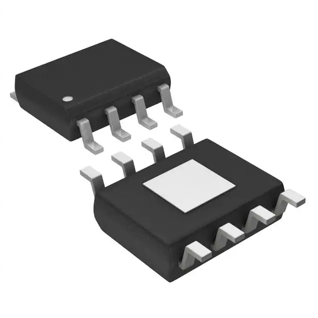
- Part No.:
- MAX5091AASA+
- Manufacturer:
- Analog Devices Inc./Maxim Integrated
- Package:
- 8-SOIC (0.154", 3.90mm Width) Exposed Pad
- Datasheet:
-
 MAX5091AASA+.pdf
- Description:
- IC REG LINEAR 5V 100MA 8SOIC
- Quantity:
- Payment:

- Shipping:

Inventory:197
Please send an inquiry. Send us your inquiry, and we will respond immediately.
Product details
Overview
MAX5091AASA+ from Maxim Integrated is a high-voltage, low-quiescent-current linear regulator with integrated reset supervisor and power-fail comparator. It delivers a fixed +5V output at up to 100mA, operates from +5V to +28V input, withstands 40V transients, features 50mV max dropout at 100mA, and includes active-low open-drain RES and SO outputs. It serves as a primary power supply and system monitor in automotive body control modules.
For engineers reviewing the MAX5091AASA+ datasheet, MAX5091AASA+ pinout, MAX5091AASA+ application, or MAX5091AASA+ equivalent, key selection considerations include its -40°C to +125°C automotive temperature range, programmable reset timeout via external capacitor, uncommitted sense comparator for voltage monitoring, thermal shutdown at +165°C, and SO-EP package's 1.5W power dissipation at +70°C.
Technical Context
The MAX5091AASA+ integrates a PNP-based LDO pass element with factory-trimmed feedback for precise +5V regulation, an always-on reset circuit monitoring VOUT against 90% of nominal output (VRT = 90% × VOUT), and a separate uncommitted comparator with 1.16V threshold (VST) on SI input. Its CT pin enables adjustable reset delay using a single capacitor, while EN provides TTL-compatible enable/disable control with internal 3.6V pullup.
Regulator stability is ensured with only 10μF ceramic output capacitance (0603 case), and fault protection includes current limiting (260mA typ), short-circuit survival at VS ≤ 16V, and thermal shutdown with 20°C hysteresis. The SO-EP package's exposed paddle connects internally to GND and requires PCB copper attachment for thermal performance.
Key Specifications
| Parameter | Value and Actual Design Meaning |
|---|---|
| Output Voltage | +5.00V ±1%, stable across -40°C to +125°C and 1mA–100mA load |
| Input Voltage Range | +5V to +28V continuous; withstands +40V transients ≤1s for load-dump immunity |
| Max Output Current | 100mA guaranteed with SO-EP package at TA ≤ +70°C (derates to 0W at TA ≥ +150°C) |
| Quiescent Current | 45μA typical at 100μA load; rises to 4.5mA at 100mA load-critical for always-on systems |
| Dropout Voltage | ≤500mV at 100mA load (VS ≥ 5.5V), enabling operation down to 5.5V input for 5V output |
| Reset Threshold | 90% of VOUT (4.5V typ) with 45mV hysteresis-ensures clean power-on sequencing |
| Thermal Shutdown | Triggers at TJ = +165°C with +20°C hysteresis-prevents permanent damage during overload |
Pinout & Package
The MAX5091AASA+ is housed in an 8-pin SO-EP (Small Outline–Exposed Pad) package with JEDEC MO-153AC outline, 1.5W thermal rating at +70°C, and θJA = 52°C/W. The exposed paddle (EP) must be soldered to PCB ground plane for effective heat dissipation and electrical grounding.
| Pin/Terminal | Circuit Role | Design Meaning |
|---|---|---|
| 1. VS | Regulator Input Supply | Accepts +5V to +28V; bypassed with 10μF capacitor to GND; withstands 40V transients |
| 2. SI | Sense Input / Noninverting Comparator Input | Monitors external voltage divider; trips SO low when VSI falls below 1.16V threshold |
| 3. EN | Enable Input | TTL-compatible; internal 3.6V pullup enables default operation; logic low disables regulator and reduces IQ to 17μA |
| 4. CT | Reset Timeout Capacitor | Connects to GND to set reset pulse delay (tRD = 35μs + 10⁶ × CCT); pulled low during reset/shutdown |
| 5. GND | Ground Reference | Common return for input/output capacitors and exposed paddle; critical for thermal and noise performance |
| 6. RES | Active-Low Reset Output | Open-drain; requires external pullup to VOUT; asserts low when VOUT < 4.5V and holds for programmed tRD |
| 7. SO | Sense Output / Power-Fail Indicator | Open-drain; asserts low when SI voltage drops below 1.16V-used for brownout detection |
| 8. VOUT | Regulated Output | Fixed +5V; stable with 10μF ceramic capacitor; supplies microcontroller core or I/O rails |
Key Features
| Feature | Design Value |
|---|---|
| Wide Input Range with Transient Tolerance | +5V to +28V operation and 40V transient survival enable use in 12V/24V automotive systems without external clamping |
| Low Quiescent Current Architecture | 45μA IQ at light load preserves battery life in always-on vehicle modules such as door controllers and sensor nodes |
| Integrated Dual Supervision Functions | Separate RES (VOUT monitor) and SO (SI monitor) outputs allow independent power-good and power-fail signaling |
| Programmable Reset Timeout | External CT capacitor sets reset pulse width from 35μs to >100ms-eliminates need for discrete RC timing networks |
| Robust Fault Protection | Current limit (260mA typ), thermal shutdown (+165°C), and short-circuit survivability (VS ≤ 16V) reduce system-level protection components |
Applications
| Automotive Body Control Module | Industrial PLC I/O Power |
|---|---|
Use Scenario: Powers microcontroller, CAN transceiver, and door lock actuator drivers in vehicle body control units exposed to load dump and cold-crank conditions. IC Role / Device Role / Timing Role: Primary 5V LDO regulator and system supervisor-provides regulated rail and generates reset signal after battery recovery. Use Value: Withstands 40V transients and operates down to -40°C, eliminating need for external TVS diodes or heater circuits in under-hood applications. | Use Scenario: Supplies isolated 5V logic power to digital input/output cards in programmable logic controllers operating in factory environments with noisy 24V DC bus. IC Role / Device Role / Timing Role: Local point-of-load regulator with power-fail detection-monitors 24V bus via SI divider and asserts SO on undervoltage. Use Value: Uncommitted SI/SO comparator replaces discrete op-amp supervision, reducing BOM count while supporting configurable trip points. |
| Home Security Panel Power | Telecom Remote Terminal Unit |
Use Scenario: Powers ARM-based security panel MCU and cellular modem during AC power loss, backed by 12V battery with wide-input tolerance. IC Role / Device Role / Timing Role: Always-on 5V regulator with programmable reset-delivers clean startup after battery switchover and ensures firmware reload on brownout. Use Value: 45μA quiescent current extends battery backup runtime; RES timeout configured via CT capacitor matches system boot sequence timing. | Use Scenario: Provides 5V supply and power integrity monitoring for remote radio head control boards in outdoor telecom cabinets subject to wide ambient temperature swings. IC Role / Device Role / Timing Role: High-reliability LDO with automotive-grade temp range (-40°C to +125°C) and thermal shutdown-maintains operation in uncooled enclosures. Use Value: SO-EP package's 1.5W dissipation and 52°C/W θJA enable full 100mA output at +85°C ambient without derating. |
Equivalent & Alternatives
The following parts are listed as comparable options for similar high-voltage LDO with reset and supervision applications.
| Alternative Part | Technical Difference | Application Difference | Selection Advice |
|---|---|---|---|
| TPS7B6750QDGNRQ1 | +3.5V to +40V input; fixed 5V output; 150mA; integrated watchdog timer; no sense comparator | Lacks SI/SO power-fail monitoring; adds watchdog functionality not present in MAX5091AASA+ | Select when system requires watchdog reset but does not need independent voltage monitoring on a second rail |
| LM2940T-5.0/NOPB | +6V to +26V input; fixed 5V output; 1A; no reset or sense functions; higher IQ (10mA) | Provides higher current but no supervision features-requires external reset IC and comparator for equivalent functionality | Select when only basic 5V regulation is needed and board space allows discrete supervision components |
Compared with TPS7B6750QDGNRQ1 and LM2940T-5.0/NOPB, the MAX5091AASA+ uniquely combines 100mA LDO regulation, programmable reset timeout, and dual-supervision (RES + SO) in a single SO-EP package-reducing component count and PCB area where both power-good and power-fail detection are required.
Availability
MAX5091AASA+ is available at Aetrix Electronics and suitable for automotive body electronics, industrial PLC I/O modules, home security panels, and telecom remote terminal units requiring stable component supply across extended temperature and transient-voltage conditions.
Supply support for MAX5091AASA+ includes scheduled delivery planning, volume procurement assistance, BOM continuity management, traceable sourcing, and lifecycle availability coordination for OEM customers, industrial embedded developers, connected-device designers, and electronics production programs.
Manufacturer
Maxim Integrated, now part of Analog Devices, designs precision analog, mixed-signal, and power-management ICs for automotive, industrial, and communications markets.
The MAX5091AASA+ belongs to Maxim's high-voltage LDO family engineered for automotive body electronics and industrial control systems requiring robust input transient handling, low IQ, and integrated power supervision.
FAQ
What is the maximum input voltage the MAX5091AASA+ can withstand without damage?
The MAX5091AASA+ withstands input transients up to +40V for durations ≤1 second, as specified in its Absolute Maximum Ratings. Continuous operation is rated from +5V to +28V. This 40V transient capability protects against automotive load-dump events. Exceeding +40V-even briefly-may cause permanent damage, so external clamping is recommended if higher transients are expected in the system design. The MAX5091AASA+'s internal protection does not extend beyond this limit.
How is the reset timeout period configured on the MAX5091AASA+?
The reset timeout period on the MAX5091AASA+ is set by connecting an external capacitor between the CT pin and GND. The delay follows tRD ≈ 35μs + (10⁶ × CCT), where CCT is in farads-for example, a 100nF capacitor yields ~100ms delay. CT is pulled high to VOUT during normal operation and driven low during reset, shutdown, or thermal fault. No resistor is required; only the capacitor determines timing. The MAX5091AASA+ datasheet provides the exact equation and tolerance band for production design.
Does the MAX5091AASA+ require an external pullup resistor on the RES pin?
Yes, the MAX5091AASA+ RES pin is an open-drain output and requires an external pullup resistor to VOUT. Typical values range from 10kΩ to 100kΩ, selected to ensure VRL ≤ 0.4V when sinking up to 825μA. The pullup establishes the high state (logic high) when the internal MOSFET is off; without it, RES remains floating and cannot signal reset completion. This requirement applies identically to the SO pin. The MAX5091AASA+ does not include internal pullups on either RES or SO.
Can the MAX5091AASA+ operate with a 3.3V input supply?
No, the MAX5091AASA+ cannot regulate from a 3.3V input. Its minimum input voltage is +5V for proper regulation, and its dropout voltage is 500mV at 100mA-so it requires at least 5.5V input to sustain 5V output under full load. At lower inputs (e.g., 4.75V), output collapses into dropout with increasing load. The device will not function below +5V, and attempting to operate it at 3.3V may result in undefined behavior or failure to start. For 3.3V input systems, a different regulator architecture is required. The MAX5091AASA+ is strictly a high-input LDO.
What is the thermal performance difference between the SO-EP and TDFN-EP packages for the MAX5091AASA+?
The MAX5091AASA+ uses the SO-EP package (θJA = 52°C/W, PD = 1.538W at +70°C), whereas the TDFN-EP variant (MAX5091AATA+T) offers superior thermal performance (θJA = 41°C/W, PD = 1.951W at +70°C). The SO-EP's higher junction-to-ambient resistance means it reaches thermal shutdown faster under identical load/ambient conditions. For designs requiring >100mA at elevated temperatures or limited PCB copper area, the TDFN-EP is preferred-but the MAX5091AASA+ itself is only offered in SO-EP, so thermal design must accommodate its 52°C/W rating.
MAX5091AASA+ Specifications
- Product attributes
- Attribute value
- Manufacturer:
- Analog Devices Inc./Maxim Integrated
- Series:
- -
- Package/Case:
- 8-SOIC (0.154", 3.90mm Width) Exposed Pad
- Packaging:
- Tube
- Product Status:
- Active
- Output Configuration:
- Positive
- Output Type:
- Fixed
- Number of Regulators:
- 1
- Voltage - Input (Max):
- 28V
- Voltage - Output (Min/Fixed):
- 5V
- Voltage - Output (Max):
- -
- Voltage Dropout (Max):
- 0.5V @ 100mA
- Current - Output:
- 100mA
- Current - Quiescent (Iq):
- 100 µA
- Current - Supply (Max):
- 10 mA
- PSRR:
- -
- Control Features:
- Enable, Reset
- Protection Features:
- Over Current, Over Temperature, Short Circuit
- Operating Temperature:
- -40°C ~ 125°C
- Grade:
- -
- Qualification:
- -
- Mounting Type:
- Surface Mount
- Supplier Device Package:
- 8-SOIC-EP
MAX5091AASA+ FAQ
1.How can I place an order for MAX5091AASA+ through Aetrix?
Please submit a Request for Quotation (RFQ) for MAX5091AASA+ on Aetrix. Our sales agent will provide a competitive quotation and guide you through the order confirmation once you accept the terms.
2.Are the price and stock information for MAX5091AASA+ reliable?
The price and inventory of MAX5091AASA+ are updated periodically and may fluctuate due to market conditions. Stock and pricing data are typically refreshed every 24 hours. Quotation validity for MAX5091AASA+ is usually 5 days.
3.What payment methods are accepted for MAX5091AASA+?
We accept Wire Transfer, PayPal, Credit Card, Western Union, MoneyGram, and Escrow for MAX5091AASA+ transactions.
Note: Certain payment methods may incur a processing fee.
4.How is shipping managed for MAX5091AASA+?
MAX5091AASA+ orders can be shipped via leading logistics carriers, including DHL, UPS, FedEx, TNT, or Registered Mail.
Once your MAX5091AASA+ order is processed, you will receive an email with the shipment details and tracking number.
Note: Tracking information may take up to 24 hours to appear. Express delivery typically takes 3–5 business days.
5.How can I obtain technical support or documentation for MAX5091AASA+?
For technical support, including MAX5091AASA+ datasheets, pinout diagrams, or application guidance, please contact our engineering support team. They can provide detailed documentation and assistance for your MAX5091AASA+ requirements.
6.How does Aetrix verify that MAX5091AASA+ is sourced from the original manufacturer or authorized distributors?
All MAX5091AASA+ products on Aetrix are procured from qualified distributors and authorized channels. Our dedicated quality assurance team conducts strict verification, including traceability checks and, if necessary, third-party testing. This ensures that MAX5091AASA+ meets industry standards.
7.What is the process for return or replacement of MAX5091AASA+?
All MAX5091AASA+ units undergo pre-shipment inspection (PSI). If there is an issue with MAX5091AASA+, returns or replacements are accepted under the following conditions:
1.Quantity discrepancies, incorrect items, or visible external defects (such as breakage or corrosion), acknowledged by Aetrix.
2.The issue is reported within 90 days of delivery.
3.The MAX5091AASA+ part is unused and in its original packaging.
Return procedure for MAX5091AASA+:
1.Submit a request within 90 days.
2.Obtain a Return Material Authorization (RMA) from Aetrix.
MAX5091AASA+ Tags

-
MIC5504-1.8YM5-TR
Microchip Technology
-
MIC5504-3.3YM5-TR
Microchip Technology

-
MIC5365-3.0YC5-TR
Microchip Technology
-
MIC5365-1.8YC5-TR
Microchip Technology
-
MIC5365-2.5YC5-TR
Microchip Technology
-
MIC5365-3.3YC5-TR
Microchip Technology

-
MIC5365-3.3YD5-TR
Microchip Technology

-
MIC5317-3.3YM5-TR
Microchip Technology

-
TLV1117LV33DCYR
Texas Instruments

-
MIC5317-3.3YMT-TZ
Microchip Technology

-
MIC5528-3.3YMT-TR
Microchip Technology

-
TLV75801PDRVR
Texas Instruments
Tech Hub
A D latch stores one bit while Enable controls when data can pass. This reference covers gate-level operation, truth tables, transparency, setup and hold timing, LE versus OE, common ICs and practical …

An SR latch stores one bit through cross-coupled feedback. This engineering reference covers NOR and NAND implementations, truth tables, forbidden-state recovery, gated operation, switch debouncing, fa…

Latch circuits retain one bit through feedback. This technical reference covers SR and D latches, truth tables, transparency, timing limits, latch-versus-flip-flop behavior, applications and common log…

An engineering guide to LED driver operation, constant-current and constant-voltage outputs, linear and switching topologies, dimming, IC selection, calculations, replacement compatibility, and fault c…

Operational amplifier guide covering op amp basics, feedback, ideal vs real op amps, common configurations, buffer circuits, offset, bias current, gain-bandwidth, slew rate, rail-to-rail limits and sel…

Jumper cables guide covering safe connection order, red and black clamp placement, final ground connection, cable gauge, length, clamp quality, copper vs CCA cables, jump starter comparison and battery…

LDO regulator guide covering low dropout voltage, power dissipation, thermal design, PSRR, output noise, capacitor stability, adjustable LDO circuits, LDO vs buck converter and datasheet selection chec…

Conditional Access Module guide covering CAM meaning, CI/CI+ interface, smart card authorization, DVB security workflow, TV and set-top box compatibility, internal electronics, ESD protection, connecto…

Guide to electronic component obsolescence covering EOL risk, PCN/PDN notices, last-time buy planning, replacement options, form-fit-function validation, counterfeit risk and BOM lifecycle management.

18650 battery guide covering lithium-ion cell basics, 3.6V/3.7V voltage, 4.2V charging, mAh and Wh capacity, protected cells, chargers, BMS, series-parallel packs, holders, welding and sourcing checks.…


