
 My Inquiry
 My Account


Analog Devices Inc./Maxim Integrated MAX6827TUT
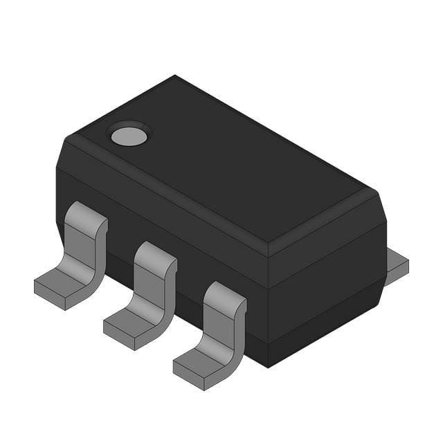
- Part No.:
- MAX6827TUT
- Manufacturer:
- Analog Devices Inc./Maxim Integrated
- Category:
- Supervisors
- Package:
- SOT-23-6
- Datasheet:
-
 MAX6827TUT.pdf
- Description:
- IC SUPERVISOR 2 CHANNEL SOT23-6
- Quantity:
- Payment:

- Shipping:

Inventory:2,500
Please send an inquiry. Send us your inquiry, and we will respond immediately.
Product details
Overview
MAX6827TUT from Maxim Integrated is a dual ultra-low-voltage microprocessor supervisory circuit in SOT23-6 package, monitoring primary supply (VCC) and user-adjustable secondary input (RESET IN), asserting active-high push-pull RESET on threshold violation, manual reset, or watchdog timeout. It supports VCC down to +1.0V, features 140ms min reset timeout, 1.6s watchdog period, and operates across –40°C to +125°C for battery-powered and automotive systems.
For engineers reviewing the MAX6827TUT datasheet, MAX6827TUT pinout, MAX6827TUT application, or MAX6827TUT equivalent, this page delivers verified specifications, validated pin functions, confirmed dual-supply monitoring behavior, real-world timing values (tRP ≥140ms, tWD ≈1.6s), and precise alternative selection guidance for industrial embedded and multivoltage µP reset management.
Technical Context
The MAX6827TUT integrates two independent voltage comparators-one factory-trimmed for VCC (threshold suffix T = 3.08V), one high-impedance RESET IN input with 0.63V typical trip point-feeding an OR logic gate that triggers a reset timeout delay generator. Its push-pull RESET output drives high during assertion, sourcing up to 800µA at VCC ≥4.75V while maintaining valid state down to VCC = +1.0V.
Watchdog functionality relies on edge detection at WDI: any absence of rising/falling transitions beyond 1.6s (min 0.80s, max 2.60s over temperature) forces reset; internal timer clears on MR low, RESET assertion, or WDI edge. MR includes 50kΩ internal pullup and rejects <100ns glitches.
Key Specifications
| Parameter | Value and Actual Design Meaning |
|---|---|
| VCC Reset Threshold | 3.08V (factory-trimmed, ±3% over –40°C to +125°C); ensures reliable reset initiation when main supply drops below nominal 3.3V rail. |
| RESET IN Threshold | 0.63V (typical); enables user-defined secondary voltage monitoring via external resistor divider down to 0.6V. |
| Reset Timeout Period | 140ms minimum; guarantees µP remains held in reset long enough for stable power recovery before release. |
| Watchdog Timeout | 1.6s nominal (0.80–2.60s over temp); provides robust software execution monitoring without excessive timeout latency. |
| Operating Voltage Range | +1.0V to +5.5V on VCC; allows full reset functionality even during deep brownout conditions where VCC dips near 1V. |
| Output Type | Active-high push-pull RESET; eliminates need for external pullup and directly interfaces with µP reset inputs requiring active-high assertion. |
| Supply Current | 30µA max at –40°C to +125°C (VCC = +3.6V); enables ultra-low-power operation in portable and battery-critical applications. |
Pinout & Package
MAX6827TUT is housed in a 6-pin SOT23-6 package (JEDEC MO-178AA), 2.9mm × 1.6mm × 1.1mm, surface-mount, lead-free compatible (replaces "-T" with "+T" for RoHS-compliant ordering).
| Pin/Terminal | Circuit Role | Design Meaning |
|---|---|---|
| 1 | RESET | Active-high push-pull reset output; asserts high during fault condition and holds for full timeout period; sinks ≤0.3V at 3.2mA, sources ≥0.8×VCC at 800µA. |
| 2 | GND | Ground reference for all internal comparators, timers, and output stage; must be low-impedance connection to system ground plane. |
| 3 | MR | Manual reset input, active-low with 50kΩ internal pullup to VCC; pulse low ≥1µs to force reset; immune to <100ns noise spikes. |
| 4 | WDI | Watchdog input; edge-sensitive (rising/falling); internal driver toggles low-high-low every ~1.4s if left floating; accepts CMOS-level signals. |
| 5 | RESET IN | User-adjustable monitor input; high-impedance comparator input with 0.63V threshold; connects to resistor divider for custom VMONITOR trip points ≥0.63V. |
| 6 | VCC | Main supply input; powers internal circuitry and defines operating range; device guaranteed functional down to +1.0V on this pin. |
Key Features
| Feature | Design Value |
|---|---|
| Dual independent voltage monitoring | Simultaneously supervises VCC (3.08V threshold) and user-defined RESET IN (0.63V base), enabling flexible multirail system reset coordination. |
| Guaranteed reset validity to VCC = +1.0V | Ensures deterministic reset assertion even during severe brownout-no undefined output states or metastability below 1.2V. |
| No external components required | Integrates precision voltage references, timeout delay generator, watchdog timer, and push-pull driver-eliminates discrete RC networks and comparators. |
| Immunity to short negative VCC transients | Withstands ≤20µs negative glitches down to 100mV below threshold without spurious reset-critical for noisy automotive or industrial power rails. |
| Factory-trimmed thresholds with tight tolerance | VCC threshold accuracy ±3% over full temperature range (–40°C to +125°C), reducing design margining and qualification effort. |
Applications
| Portable Power Management | Automotive Body Control Module |
|---|---|
|
Use Scenario: Supervising 3.3V main rail and 1.2V core voltage in handheld medical diagnostic device with Li-ion battery supply. IC Role / Device Role / Timing Role: Dual-supply monitor asserting active-high RESET to ARM Cortex-M4 during VCC sag or RESET IN undervoltage; 140ms timeout prevents premature boot. Use Value: Prevents corrupted firmware execution during battery discharge cycles where VCC drops from 3.6V to 2.8V; RESET IN monitors LDO output stability. |
Use Scenario: Monitoring MCU supply and CAN transceiver VIO rail in door module ECU exposed to load dump and cold-crank conditions. IC Role / Device Role / Timing Role: Primary VCC supervisor (3.08V) detects battery dip below 3.0V; RESET IN tracks 2.5V I/O rail via divider; push-pull RESET drives µP reset pin directly. Use Value: Eliminates need for external level-shifting or pullup resistors; guaranteed operation down to VCC = +1.0V ensures reset integrity during cold-crank (6V–7V start). |
| Industrial PLC I/O Card | Smart Sensor Node |
|
Use Scenario: Ensuring reliable startup and brownout recovery for dual-core µP on modular I/O card powered by isolated 3.3V and 5V supplies. IC Role / Device Role / Timing Role: VCC monitors 3.3V logic rail; RESET IN monitors 5V analog front-end supply via R-divider; MR enables field-service reset button. Use Value: 1.6s watchdog guards against firmware lockup in harsh EMI environments; 50kΩ MR pullup simplifies BOM and layout. |
Use Scenario: Providing fail-safe reset for ultra-low-power BLE SoC (nRF52840) operating from coin cell, with separate 1.8V sensor bias rail. IC Role / Device Role / Timing Role: VCC monitors 3.0V regulator output; RESET IN tracks 1.8V sensor rail using 2-resistor divider; WDI tied to GPIO for software watchdog. Use Value: 30µA max ICC enables >10-year battery life; 0.63V RESET IN threshold allows accurate 1.8V monitoring with <1% error using standard 1% resistors. |
Equivalent & Alternatives
The following parts are listed as comparable options for similar microprocessor supervisory applications.
| Alternative Part | Technical Difference | Application Difference | Selection Advice |
|---|---|---|---|
| MAX6826TUT | Active-low push-pull RESET output; identical VCC threshold (3.08V), RESET IN, MR, and WDI functionality. | Requires µP with active-low reset input; incompatible with active-high-only reset pins without inversion logic. | Select MAX6826TUT only when target µP mandates active-low reset assertion and no level translation is acceptable. |
| MAX6828TUT | Open-drain RESET output; same VCC/RESET IN thresholds and timing specs; requires external pullup resistor. | Suitable for bidirectional reset pins (e.g., Motorola 68HC11); enables wired-OR reset bus sharing with other supervisors or µP outputs. | Choose MAX6828TUT when system architecture demands open-drain reset signaling or multi-source reset arbitration. |
Compared with MAX6826TUT and MAX6828TUT, the MAX6827TUT uniquely delivers active-high push-pull RESET-reducing component count, eliminating pullup resistor uncertainty, and ensuring direct compatibility with modern µPs featuring active-high reset inputs like STM32L4 or PIC32MX.
Availability
MAX6827TUT is available at Aetrix Electronics and suitable for portable/battery-powered equipment, automotive systems, and industrial embedded controllers requiring stable component supply across extended temperature ranges and long production lifecycles.
Supply support for MAX6827TUT includes scheduled delivery planning, volume procurement assistance, BOM continuity management, traceable sourcing, and lifecycle availability coordination for OEM customers, industrial embedded developers, connected-device designers, and electronics production programs.
Manufacturer
Maxim Integrated (now part of Analog Devices) designs precision analog, mixed-signal, and power management ICs for demanding industrial, automotive, and computing applications.
The MAX6826–MAX6831 family was engineered specifically for dual-rail microprocessor supervision in space-constrained, low-voltage systems-delivering factory-trimmed accuracy, guaranteed sub-1.2V operation, and integrated watchdog functionality in 6-pin SOT23.
FAQ
What is the exact reset threshold voltage for MAX6827TUT?
The MAX6827TUT has a factory-trimmed VCC reset threshold of 3.08V (±3% over –40°C to +125°C), corresponding to the 'T' suffix in its part number. This value is specified in the Electrical Characteristics table under VTH for MAX68__T devices and is guaranteed across the full operating temperature range without external calibration.
Does MAX6827TUT support monitoring a secondary voltage below 1.0V?
Yes, the MAX6827TUT supports secondary voltage monitoring down to 0.63V via its RESET IN pin. By connecting an external resistor divider between the target rail and GND, users can scale higher voltages to match the 0.63V internal comparator threshold-enabling accurate supervision of rails such as 1.2V, 1.8V, or 2.5V with minimal external components.
What is the watchdog timeout behavior of MAX6827TUT under temperature variation?
The MAX6827TUT watchdog timeout ranges from 0.80s to 2.60s over –40°C to +125°C, with a nominal 1.6s value at +25°C. This variation is characterized in the datasheet's Typical Operating Characteristics (Figure MAX6826 toc04) and reflects process and temperature dependencies of the internal RC oscillator driving the watchdog timer.
Can MAX6827TUT operate reliably when VCC drops to 1.1V?
Yes, the MAX6827TUT is guaranteed to assert and maintain a valid active-high RESET output down to VCC = +1.0V, as explicitly stated in the General Description and Absolute Maximum Ratings. At VCC = 1.1V, RESET remains fully functional-sourcing ≥0.8×VCC at 200µA and sinking ≤0.3V at 50µA-ensuring deterministic behavior during deep brownout.
How does the manual reset (MR) input behave when left unconnected?
When left unconnected, the MR input of MAX6827TUT is pulled high internally by a 50kΩ resistor to VCC, disabling manual reset. No external pullup is needed. Driving MR low for ≥1µs forces reset assertion; reset remains active for the full 140ms timeout after MR returns high, providing clean, debounced reset initiation without external circuitry.
MAX6827TUT Specifications
- Product attributes
- Attribute value
- Manufacturer:
- Analog Devices Inc./Maxim Integrated
- Series:
- -
- Package/Case:
- SOT-23-6
- Packaging:
- Bulk
- Product Status:
- Active
- Programmable:
- Not Verified
- Type:
- Multi-Voltage Supervisor
- Number of Voltages Monitored:
- 2
- Voltage - Threshold:
- 3.08V, Adj
- Output:
- Push-Pull, Totem Pole
- Reset:
- Active High
- Reset Timeout:
- 140ms Minimum
- Operating Temperature:
- -40°C ~ 125°C (TA)
- Grade:
- -
- Qualification:
- -
- Mounting Type:
- Surface Mount
- Supplier Device Package:
- SOT-23-6
MAX6827TUT FAQ
1.How can I place an order for MAX6827TUT through Aetrix?
Please submit a Request for Quotation (RFQ) for MAX6827TUT on Aetrix. Our sales agent will provide a competitive quotation and guide you through the order confirmation once you accept the terms.
2.Are the price and stock information for MAX6827TUT reliable?
The price and inventory of MAX6827TUT are updated periodically and may fluctuate due to market conditions. Stock and pricing data are typically refreshed every 24 hours. Quotation validity for MAX6827TUT is usually 5 days.
3.What payment methods are accepted for MAX6827TUT?
We accept Wire Transfer, PayPal, Credit Card, Western Union, MoneyGram, and Escrow for MAX6827TUT transactions.
Note: Certain payment methods may incur a processing fee.
4.How is shipping managed for MAX6827TUT?
MAX6827TUT orders can be shipped via leading logistics carriers, including DHL, UPS, FedEx, TNT, or Registered Mail.
Once your MAX6827TUT order is processed, you will receive an email with the shipment details and tracking number.
Note: Tracking information may take up to 24 hours to appear. Express delivery typically takes 3–5 business days.
5.How can I obtain technical support or documentation for MAX6827TUT?
For technical support, including MAX6827TUT datasheets, pinout diagrams, or application guidance, please contact our engineering support team. They can provide detailed documentation and assistance for your MAX6827TUT requirements.
6.How does Aetrix verify that MAX6827TUT is sourced from the original manufacturer or authorized distributors?
All MAX6827TUT products on Aetrix are procured from qualified distributors and authorized channels. Our dedicated quality assurance team conducts strict verification, including traceability checks and, if necessary, third-party testing. This ensures that MAX6827TUT meets industry standards.
7.What is the process for return or replacement of MAX6827TUT?
All MAX6827TUT units undergo pre-shipment inspection (PSI). If there is an issue with MAX6827TUT, returns or replacements are accepted under the following conditions:
1.Quantity discrepancies, incorrect items, or visible external defects (such as breakage or corrosion), acknowledged by Aetrix.
2.The issue is reported within 90 days of delivery.
3.The MAX6827TUT part is unused and in its original packaging.
Return procedure for MAX6827TUT:
1.Submit a request within 90 days.
2.Obtain a Return Material Authorization (RMA) from Aetrix.
MAX6827TUT Tags
-
MIC826SYMT-TR
Microchip Technology

-
APX803S-31SA-7
Diodes Incorporated
-
APX803L20-29SA-7
Diodes Incorporated

-
TPS3828-33DBVR
Texas Instruments

-
V6340RSP3B+
EM Microelectronic
-
EM6325CXSP5B-2.9+
EM Microelectronic
-
MCP120T-300I/TT
Microchip Technology
-
MCP130T-315I/TT
Microchip Technology
-
MCP120T-475I/TT
Microchip Technology
-
MCP111T-300E/TT
Microchip Technology
-
MCP120T-315I/TT
Microchip Technology
-
MCP809T-315I/TT
Microchip Technology
Tech Hub

A practical engineering guide to 3.3V and 5V logic compatibility, input thresholds, resistor dividers, translator ICs, MOSFET level shifting, I2C pull-ups, timing limits and power-sequencing risks.

The 74HC595 uses push-pull logic outputs, while the TPIC6B595 uses 50 V open-drain DMOS sinks for higher-power loads. This guide compares timing, current limits, 3.3 V interfacing, load wiring, thermal…

The 74HC595 converts serial data into eight stable parallel outputs. This guide covers pin functions, shift and storage timing, OE and MR behavior, drive-current limits, cascading, voltage compatibilit…

A technical comparison of level-sensitive latches and edge-triggered flip-flops, covering timing windows, setup and hold limits, master–slave operation, time borrowing, race-through, HDL inference and…

A D latch stores one bit while Enable controls when data can pass. This reference covers gate-level operation, truth tables, transparency, setup and hold timing, LE versus OE, common ICs and practical …

An SR latch stores one bit through cross-coupled feedback. This engineering reference covers NOR and NAND implementations, truth tables, forbidden-state recovery, gated operation, switch debouncing, fa…

Latch circuits retain one bit through feedback. This technical reference covers SR and D latches, truth tables, transparency, timing limits, latch-versus-flip-flop behavior, applications and common log…

An engineering guide to LED driver operation, constant-current and constant-voltage outputs, linear and switching topologies, dimming, IC selection, calculations, replacement compatibility, and fault c…

Operational amplifier guide covering op amp basics, feedback, ideal vs real op amps, common configurations, buffer circuits, offset, bias current, gain-bandwidth, slew rate, rail-to-rail limits and sel…

Jumper cables guide covering safe connection order, red and black clamp placement, final ground connection, cable gauge, length, clamp quality, copper vs CCA cables, jump starter comparison and battery…


