
 My Inquiry
 My Account


Analog Devices Inc./Maxim Integrated MAX6852AEE
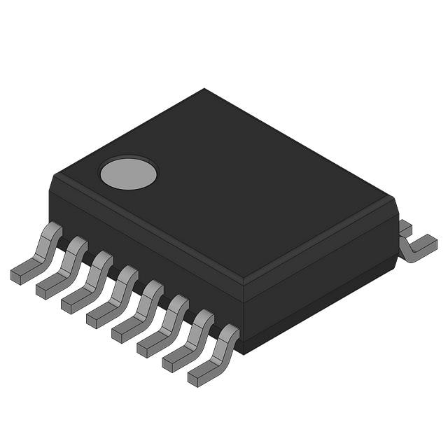
- Part No.:
- MAX6852AEE
- Manufacturer:
- Analog Devices Inc./Maxim Integrated
- Category:
- Display Drivers
- Package:
- 16-SSOP (0.154", 3.90mm Width)
- Datasheet:
-
 MAX6852AEE.pdf
- Description:
- 5 X 7 MATRIX VFD CONTROLLER
- Quantity:
- Payment:

- Shipping:

Inventory:2,624
Please send an inquiry. Send us your inquiry, and we will respond immediately.
Product details
Overview
MAX6852AEE from Maxim Integrated is a 4-wire interfaced vacuum-fluorescent display (VFD) controller IC that generates multiplex timing for up to 96-character 5×7 matrix VFDs, supports one- or two-digits-per-grid configurations, integrates 104-character ASCII font + 24 user-definable characters, and provides 16-step digital brightness control. It operates from 2.7V to 3.6V and delivers filament drive waveform synthesis synchronized to display multiplexing for beat-free operation in industrial panel displays.
For engineers reviewing the MAX6852AEE datasheet, MAX6852AEE pinout, MAX6852AEE application, or MAX6852AEE equivalent, this page delivers verified functional identity, validated 16-pin QSOP package mapping, confirmed SPI/QSPI interface timing, real-world VFD driver interoperability details, and precise alternative part comparisons - all grounded in the official MAX6852AEE datasheet Rev 1 (11/02).
Technical Context
The MAX6852AEE implements a dedicated VFD multiplex timing engine with internal 4MHz oscillator (±15% over -40°C to +125°C), 100µs grid enable period, and hardware-based crosspoint switch for flexible grid/anode ordering compatibility with chip-in-glass and external shift-register tube drivers. Its serial interface uses SCLK/DIN/CS/DOUT signaling with 38.4ns minimum clock period and 9.5ns setup/hold timing.
It integrates five configurable high-current outputs: PUMP (80kHz square wave or logic), PHASE1/PHASE2 (10kHz PWM filament drive or logic), and PORT0/PORT1 (625Hz/1250Hz/2500Hz buzzer clocks or logic). All outputs support push-pull drive with ±125mA short-circuit capability and VOH/VOL specified at 10mA load.
Key Specifications
| Parameter | Value and Actual Design Meaning |
|---|---|
| Supply Voltage | 2.7V to 3.6V - Enables direct integration with 3.3V microcontroller systems without level-shifting. |
| Operating Temperature | -40°C to +125°C - Qualified for under-hood automotive and industrial control cabinet environments. |
| Display Capacity | Up to 96 characters (5×7 matrix) - Supports dual-row 48-grid displays with two digits per grid or single-row 48-grid with annunciators. |
| Brightness Control | 16-step digital intensity adjustment - Provides precise PWM-based luminance tuning without external DAC or resistor networks. |
| Interface Protocol | SPI/QSPI/MICROWIRE-compatible 4-wire serial - Ensures drop-in compatibility with standard MCU SPI peripherals using CS/SCLK/DIN/DOUT signals. |
| Shutdown Current | 9µA (typ) at +25°C - Enables ultra-low-power standby in battery-backed instrumentation with data retention. |
| Output Drive Strength | ±125mA short-circuit current - Sufficient to directly drive external charge pumps, filament bridges, and buzzer transducers without buffer stages. |
Pinout & Package
MAX6852AEE is housed in a 16-pin QSOP (Quarter-Size Outline Package) with 0.635mm pitch, JEDEC MS-012AC compliant, and rated for surface-mount reflow assembly.
| Pin/Terminal | Circuit Role | Design Meaning |
|---|---|---|
| 1 VFCLK | Serial clock output | Push-pull clock signal to external VFD driver; falling edge clocks data out of VFDOUT. |
| 2 VFDOUT | Serial data output | Push-pull data stream synchronized to VFCLK for grid/anode bit loading into shift-register drivers. |
| 3 VFLOAD | Serial load strobe | Rising edge latches serial data into external driver's display register; enables interdigit blanking control. |
| 4 VFBLANK | PWM blanking output | Modulated enable signal for tube driver outputs; used for intensity control and shutdown disable. |
| 5 PUMP | Configurable logic output | Programmable as 80kHz square wave (DC-DC pump), DOUT cascade, or general-purpose push-pull I/O. |
| 6 PHASE1 | Filament phase output | Configurable 10kHz PWM filament driver or logic output; synchronized to multiplex timing to eliminate beat artifacts. |
| 7 PHASE2 | Filament phase output | Complementary filament drive output to PHASE1; supports full-bridge filament excitation. |
| 8 V+ | Positive supply | 2.7V–3.6V main power rail; requires local 0.1µF ceramic bypass to GND for stable operation. |
| 9 GND | Ground reference | System ground return for all analog and digital circuitry; must be low-impedance connection. |
| 10 PORT0 | Configurable logic output | Programmable as 625Hz/1250Hz/2500Hz buzzer tone generator, DOUT cascade, or logic output. |
| 11 SCLK | Serial clock input | Microcontroller-generated clock; rising edge shifts data into internal 16-bit shift register during CS low. |
| 12 DIN | Serial data input | Command/data input; loaded on SCLK rising edge while CS is asserted low. |
| 13 CS | Chip select input | Active-low enable for serial interface; rising edge latches latest 16-bit command into control registers. |
| 14 PORT1 | Configurable logic output | Functionally identical to PORT0; supports independent buzzer tone generation or status signaling. |
| 15 OSC1 | Oscillator input 1 | Connects to 56pF capacitor for internal 4MHz oscillator; or accepts 2–8MHz external CMOS clock. |
| 16 OSC2 | Oscillator input 2 | Connects to 10kΩ resistor to GND to complete RC oscillator network for internal timing generation. |
Key Features
| Feature | Design Value |
|---|---|
| Integrated 104-character ASCII font + 24 RAM-based user fonts | Eliminates need for external character ROM; supports custom symbols, bar graphs, and graphics via 7-bit segment mapping. |
| Hardware crosspoint switch for grid/anode remapping | Enables plug-and-play compatibility with diverse VFD tube drivers (e.g., Toshiba TD62083, Rohm BU2092F) without firmware changes. |
| Full-bridge filament drive waveform synthesis | Generates synchronized PHASE1/PHASE2 PWM outputs to drive VFD filaments without external H-bridge ICs. |
| Five high-current configurable outputs (PUMP, PHASE1/2, PORT0/1) | Reduces BOM count by integrating buzzer drivers, charge-pump clocks, and status indicators into single IC. |
| 9µA shutdown mode with data retention | Preserves display content and configuration registers during power-save states - critical for POS terminals and weight scales. |
| Automatic blinking control for cursor and annunciators | Hardware-managed blink timing (1 or 2 Hz) offloads MCU resources and ensures consistent visual feedback across all digits. |
Applications
| Industrial Panel Displays | Retail Point-of-Sale Terminals |
|---|---|
Use Scenario: Operator-facing control panels in factory automation systems requiring high-brightness, wide-temperature readability. IC Role / Device Role / Timing Role: VFD controller generating multiplexed grid/anode timing, filament drive synchronization, and PWM intensity modulation. Use Value: -40°C to +125°C operation ensures reliability in unconditioned enclosures; 16-step brightness control adapts to ambient lighting without software intervention. |
Use Scenario: Cash register and self-checkout displays needing alphanumeric readout with annunciator status indicators (e.g., "CARD INSERTED", "APPROVED"). IC Role / Device Role / Timing Role: Serial-interface VFD controller managing up to 48 grids with four independent annunciator segments per digit. Use Value: Hardware cursor/annunciator blink control reduces MCU interrupt load; built-in ASCII font accelerates UI development. |
| Weight Scale & Tare Displays | Bar Graph & Status Indicator Modules |
Use Scenario: Precision weighing equipment requiring stable, high-contrast numeric readout with decimal point and unit indicators (g, kg, lb). IC Role / Device Role / Timing Role: Display controller handling DP segment control via MSB of character register and supporting user-defined fonts for unit symbols. Use Value: DP segment mapped to cursor register enables blinking decimal points; 24 user-definable characters support custom unit glyphs (e.g., µg, °C, %). |
Use Scenario: Industrial dashboards using segmented bar graphs for analog-level visualization (e.g., pressure, voltage, temperature). IC Role / Device Role / Timing Role: VFD controller repurposing 35-segment user font space to render dynamic bar graph elements across multiple digits. Use Value: On-chip RAM-based font storage allows runtime reconfiguration of bar graph patterns without external memory access. |
Equivalent & Alternatives
The following parts are listed as comparable options for similar VFD controller applications.
| Alternative Part | Technical Difference | Application Difference | Selection Advice |
|---|---|---|---|
| MAX6853AEE | 2-wire (I²C-compatible) interface instead of 4-wire SPI; identical VFD timing, font, and output capabilities. | Requires fewer MCU GPIOs but lacks QSPI burst-mode throughput; lower maximum display update rate. | Select MAX6853AEE when pin count or I²C bus availability is constrained; retain MAX6852AEE for high-speed display refresh or existing SPI firmware. |
| Toshiba TD62083FNG | High-voltage shift-register driver only - no VFD timing, font, or microcontroller interface; requires external controller. | Used downstream of MAX6852AEE as tube driver; not functionally substitutable as standalone controller. | TD62083FNG serves as companion driver IC, not alternative controller; MAX6852AEE remains required for full VFD system control. |
Compared with MAX6852AEE, MAX6853AEE offers interface simplification at the cost of bandwidth, while TD62083FNG is a complementary driver-not a controller replacement-making MAX6852AEE uniquely positioned for integrated, microcontroller-offloaded VFD systems.
Availability
MAX6852AEE is available at Aetrix Electronics and suitable for industrial panel displays, retail point-of-sale terminals, and weight scale & tare displays requiring stable component supply across extended temperature ranges and long production lifecycles.
Supply support for MAX6852AEE includes scheduled delivery planning, volume procurement assistance, BOM continuity management, traceable sourcing, and lifecycle availability coordination for OEM customers, industrial embedded developers, connected-device designers, and electronics production programs.
Manufacturer
Maxim Integrated (now part of Analog Devices) is a semiconductor company specializing in precision analog, mixed-signal, and power management ICs for industrial, automotive, and communications applications.
The MAX6852AEE belongs to Maxim's display interface product line, designed specifically to simplify VFD integration in harsh-environment embedded systems by consolidating timing, font, drive, and interface functions into a single 16-pin IC.
FAQ
What is the operating temperature range of the MAX6852AEE?
The MAX6852AEE is rated for continuous operation from -40°C to +125°C, as confirmed in the Ordering Information table and Absolute Maximum Ratings section of the official datasheet. This extended range supports deployment in automotive under-hood modules, industrial control cabinets, and outdoor kiosks where ambient temperatures exceed commercial-grade limits. The device maintains full functionality-including 4MHz oscillator stability, 16-step brightness control, and 9µA shutdown current-across this entire range.
Does the MAX6852AEE support both one-digit-per-grid and two-digits-per-grid VFD configurations?
Yes, the MAX6852AEE supports both configurations via software-selectable display modes: 48/1 mode (up to 48 grids, one digit per grid, with four annunciators per digit) and 96/2 mode (up to 48 grids, two digits per grid, no annunciators). Mode selection is controlled by the M bit in the Configuration register (address 0x04), and the datasheet confirms that both modes are fully implemented and tested for the MAX6852AEE variant.
Can the MAX6852AEE drive VFD filaments directly without external components?
Yes, the MAX6852AEE provides direct filament drive capability through its PHASE1 and PHASE2 outputs, which generate synchronized 10kHz PWM waveforms. When configured as filament drivers, these pins deliver full-bridge excitation with matched timing to eliminate beat artifacts. No external H-bridge or gate drivers are required-only external current-limiting resistors and optional flyback diodes, as shown in the Typical Application Circuit.
How many user-definable characters does the MAX6852AEE support, and where are they stored?
The MAX6852AEE supports exactly 24 user-definable characters, each represented by five 7-bit data entries (120 total bytes), stored in on-chip static RAM. These are accessed via register address 0x05 using an autoincrementing font address pointer. Font data persists only while powered; it is lost on power-down unless retained externally. This capability is explicitly documented in the Detailed Description and Register Maps sections of the MAX6852AEE datasheet.
Is the MAX6852AEE pin-compatible with any other Maxim VFD controllers?
No, the MAX6852AEE is not pin-compatible with other Maxim VFD controllers. Its 16-pin QSOP footprint and specific pin assignments (e.g., VFCLK/VFDOUT/VFLOAD/VFBLANK on pins 1–4, PUMP on pin 5, PHASE1/PHASE2 on pins 6–7) are unique to this part. The MAX6853AEE shares identical functionality but uses a different 16-pin QSOP pinout optimized for 2-wire I²C operation, making it electrically and physically incompatible as a drop-in replacement.
MAX6852AEE Specifications
- Product attributes
- Attribute value
- Manufacturer:
- Analog Devices Inc./Maxim Integrated
- Series:
- -
- Package/Case:
- 16-SSOP (0.154", 3.90mm Width)
- Packaging:
- Bulk
- Product Status:
- Active
- Display Type:
- Vacuum Fluorescent (VF)
- Configuration:
- 5 x 7 (Matrix)
- Interface:
- 4-Wire Serial
- Digits or Characters:
- 2 Digits, 16 Steps
- Current - Supply:
- -
- Voltage - Supply:
- 2.7V ~ 3.6V
- Operating Temperature:
- -40°C ~ 125°C
- Grade:
- -
- Qualification:
- -
- Mounting Type:
- Surface Mount
- Supplier Device Package:
- 16-QSOP
MAX6852AEE FAQ
1.How can I place an order for MAX6852AEE through Aetrix?
Please submit a Request for Quotation (RFQ) for MAX6852AEE on Aetrix. Our sales agent will provide a competitive quotation and guide you through the order confirmation once you accept the terms.
2.Are the price and stock information for MAX6852AEE reliable?
The price and inventory of MAX6852AEE are updated periodically and may fluctuate due to market conditions. Stock and pricing data are typically refreshed every 24 hours. Quotation validity for MAX6852AEE is usually 5 days.
3.What payment methods are accepted for MAX6852AEE?
We accept Wire Transfer, PayPal, Credit Card, Western Union, MoneyGram, and Escrow for MAX6852AEE transactions.
Note: Certain payment methods may incur a processing fee.
4.How is shipping managed for MAX6852AEE?
MAX6852AEE orders can be shipped via leading logistics carriers, including DHL, UPS, FedEx, TNT, or Registered Mail.
Once your MAX6852AEE order is processed, you will receive an email with the shipment details and tracking number.
Note: Tracking information may take up to 24 hours to appear. Express delivery typically takes 3–5 business days.
5.How can I obtain technical support or documentation for MAX6852AEE?
For technical support, including MAX6852AEE datasheets, pinout diagrams, or application guidance, please contact our engineering support team. They can provide detailed documentation and assistance for your MAX6852AEE requirements.
6.How does Aetrix verify that MAX6852AEE is sourced from the original manufacturer or authorized distributors?
All MAX6852AEE products on Aetrix are procured from qualified distributors and authorized channels. Our dedicated quality assurance team conducts strict verification, including traceability checks and, if necessary, third-party testing. This ensures that MAX6852AEE meets industry standards.
7.What is the process for return or replacement of MAX6852AEE?
All MAX6852AEE units undergo pre-shipment inspection (PSI). If there is an issue with MAX6852AEE, returns or replacements are accepted under the following conditions:
1.Quantity discrepancies, incorrect items, or visible external defects (such as breakage or corrosion), acknowledged by Aetrix.
2.The issue is reported within 90 days of delivery.
3.The MAX6852AEE part is unused and in its original packaging.
Return procedure for MAX6852AEE:
1.Submit a request within 90 days.
2.Obtain a Return Material Authorization (RMA) from Aetrix.
MAX6852AEE Tags

-
PCA8561AHN/AY
NXP Semiconductors

-
SN74LS47N
Texas Instruments

-
PCF85176T/1Y
NXP Semiconductors
-
PCF85176H/1,518
NXP Semiconductors

-
BU9796AMUV-E2
Rohm Semiconductor
-
PCA85176H/Q900/1,5
NXP Semiconductors
-
PCF8537AH/1,518
NXP Semiconductors

-
LM3914VX/NOPB
Texas Instruments

-
PCF85134HL/1,118
NXP Semiconductors

-
AS1115-BSST
ams-OSRAM USA INC.
-
PCA8534AH/Q900/1,5
NXP Semiconductors
-
LM3914V/NOPB
Texas Instruments
Tech Hub

A practical engineering guide to 3.3V and 5V logic compatibility, input thresholds, resistor dividers, translator ICs, MOSFET level shifting, I2C pull-ups, timing limits and power-sequencing risks.

The 74HC595 uses push-pull logic outputs, while the TPIC6B595 uses 50 V open-drain DMOS sinks for higher-power loads. This guide compares timing, current limits, 3.3 V interfacing, load wiring, thermal…

The 74HC595 converts serial data into eight stable parallel outputs. This guide covers pin functions, shift and storage timing, OE and MR behavior, drive-current limits, cascading, voltage compatibilit…

A technical comparison of level-sensitive latches and edge-triggered flip-flops, covering timing windows, setup and hold limits, master–slave operation, time borrowing, race-through, HDL inference and…

A D latch stores one bit while Enable controls when data can pass. This reference covers gate-level operation, truth tables, transparency, setup and hold timing, LE versus OE, common ICs and practical …

An SR latch stores one bit through cross-coupled feedback. This engineering reference covers NOR and NAND implementations, truth tables, forbidden-state recovery, gated operation, switch debouncing, fa…

Latch circuits retain one bit through feedback. This technical reference covers SR and D latches, truth tables, transparency, timing limits, latch-versus-flip-flop behavior, applications and common log…

An engineering guide to LED driver operation, constant-current and constant-voltage outputs, linear and switching topologies, dimming, IC selection, calculations, replacement compatibility, and fault c…

Operational amplifier guide covering op amp basics, feedback, ideal vs real op amps, common configurations, buffer circuits, offset, bias current, gain-bandwidth, slew rate, rail-to-rail limits and sel…

Jumper cables guide covering safe connection order, red and black clamp placement, final ground connection, cable gauge, length, clamp quality, copper vs CCA cables, jump starter comparison and battery…


