
 My Inquiry
 My Account


Analog Devices Inc./Maxim Integrated MAX6955AAX+T
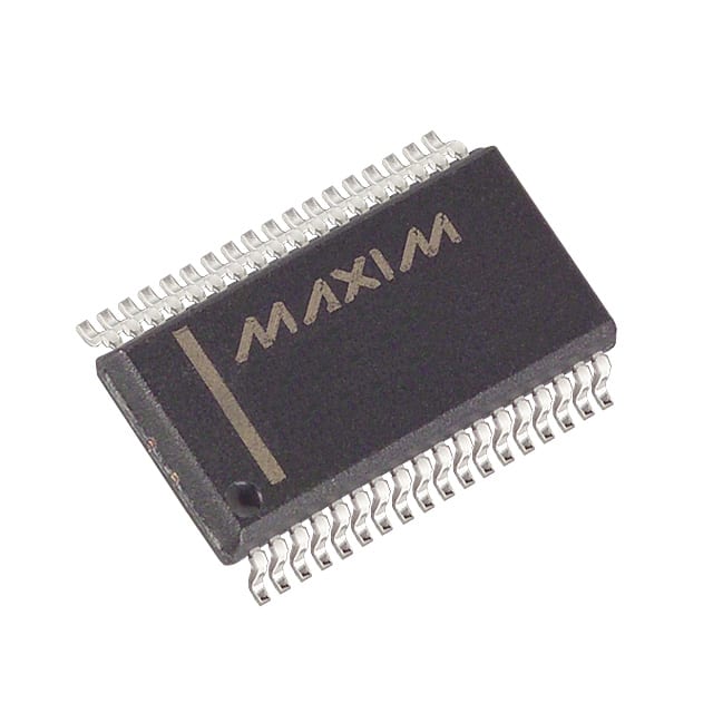
- Part No.:
- MAX6955AAX+T
- Manufacturer:
- Analog Devices Inc./Maxim Integrated
- Category:
- Display Drivers
- Package:
- 36-BSOP (0.295", 7.50mm Width)
- Datasheet:
-
 MAX6955AAX+T.pdf
- Description:
- IC DRVR 7/14/16 SEGMENT 36SSOP
- Quantity:
- Payment:

- Shipping:

Inventory:1,658
Please send an inquiry. Send us your inquiry, and we will respond immediately.
Product details
Overview
MAX6955AAX+T from Maxim Integrated is a 2-wire (I²C-compatible) LED display driver with integrated I/O expander and key-scan controller, operating from 2.7V to 5.5V. It drives up to 16 digits of 7-segment, 8 digits of 14-segment, or 128 discrete LEDs, includes five GPIOs configurable as key-scan inputs for up to 32-switch matrices, and features 16-step per-digit digital brightness control - used in panel meters and audio/video front-panel displays.
For engineers reviewing the MAX6955AAX+T datasheet, MAX6955AAX+T pinout, MAX6955AAX+T application, or MAX6955AAX+T equivalent, this page delivers verified technical context, real-world drive capability, confirmed GPIO/key-scan behavior, exact segment current slew-rate (11 mA/µs), and validated automotive-grade (-40°C to +125°C) operation in the 36-pin SSOP package.
Technical Context
The MAX6955AAX+T implements a dual-plane digit register architecture (P0/P1) enabling synchronized blinking across all digits via hardware-controlled multiplexing. Its internal RC oscillator (4.0 MHz typ at V+ = 3.3V, RSET = 56kΩ, CSET = 22pF) feeds both display scan and blink timing, with selectable fast/slow blink modes (0.5 s / 1 s period).
Segment drivers are slew-rate limited (11 mA/µs) to reduce EMI, while O0–O18 support configurable sourcing (up to –48 mA at V+ = 2.7V) or sinking (up to 935 mA total sink on O0–O7), and P0–P4/IRQ provide hysteresis (0.03 × V+) and pull-up current (75 µA at V+ = 3.3V) for robust key-scan operation with n-key rollover.
Key Specifications
| Parameter | Value and Actual Design Meaning |
|---|---|
| Supply Voltage Range | 2.7V to 5.5V - supports direct interface with 3.3V and 5V microcontrollers without level-shifting. |
| Interface Type | I²C-compatible 2-wire serial - 400 kbps max clock rate, standard slave addressing with 16 configurable addresses via AD0/AD1. |
| Display Drive Capability | Up to 16×7-seg, 8×14-seg, 8×16-seg, or 128 discrete LEDs - enables mixed-type display configurations using shared O0–O18 outputs. |
| GPIO & Key-Scan | 5 pins (P0–P4/IRQ) - configurable as open-drain outputs or key-scan inputs with automatic debouncing and IRQ assertion on valid key press. |
| Brightness Control | 16-step per-digit digital PWM - allows independent intensity tuning without external DACs or resistors. |
| Operating Temperature | –40°C to +125°C - qualified for automotive and industrial panel meter applications requiring extended thermal stability. |
| Shutdown Current | 10 µA typical - retains RAM data during low-power sleep, enabling instant resume without reinitialization. |
Pinout & Package
MAX6955AAX+T is housed in a 36-pin SSOP (Shrink Small Outline Package) with exposed paddle thermally connected to GND. Pin 17 (ISET) sets peak segment current via external resistor; pins P0–P3 serve as key-scan matrix inputs when enabled; P4 functions as IRQ output during key events.
| Pin/Terminal | Circuit Role | Design Meaning |
|---|---|---|
| P0–P3 | Key-scan input / GPIO | Internal pullups (75 µA at 3.3V) enable direct connection to switch matrix rows/columns; auto-debounced with n-key rollover support. |
| P4/IRQ | Interrupt output / GPIO | Open-drain active-low signal asserted when key event is detected and debounced - eliminates polling overhead. |
| O0–O7 | Digit common-cathode drivers | Sink up to 935 mA total - drives up to 8 common-cathode digits in 7-/14-/16-segment configurations. |
| O0–O18 | Segment anode drivers | Source up to –48 mA per output (V+ = 2.7V) - directly controls individual segments or discrete LEDs. |
| ISET | Segment current reference | Connects to GND via RSET to set precise peak segment current - enables consistent brightness across voltage/temperature. |
| OSC / OSC_OUT | Internal oscillator input / buffered clock output | OSC accepts RC network or 1–8 MHz external clock; OSC_OUT synchronizes blink timing across multiple MAX6955AAX+T devices. |
| BLINK | Open-drain blink clock output | Drives external timing loads or cascades to other display drivers - enables system-wide blink coordination without MCU intervention. |
| SCL / SDA | I²C clock/data lines | Standard 400 kbps I²C interface with 0.7×V+ VIH threshold - interoperable with most ARM, PIC, and ESP32 host controllers. |
Key Features
| Feature | Design Value |
|---|---|
| Integrated 104-character ASCII font | Eliminates external character ROM - supports full alphanumeric display on 14-/16-segment panels including £, €, ¥, ±, ↑, ↓ symbols. |
| Hardware blink control | Automatic P0/P1 plane switching synchronized to OSC - enables flicker-free, MCU-free blinking across all digits or segments. |
| Slew-rate-limited segment drivers | 11 mA/µs dI/dt limit reduces radiated EMI - meets Class B emissions requirements without added ferrites or shielding. |
| Digit-by-digit brightness control | 16-step PWM per digit stored in RAM - allows dynamic contrast adjustment (e.g., dim leading zeros, bright status indicators). |
| Power-up blanking & shutdown retention | Display remains off until initialized; shutdown mode draws only 10 µA while preserving digit register contents - critical for battery-backed systems. |
Applications
| Panel Meters | Audio/Video Front Panels |
|---|---|
Use Scenario: Digital voltmeter or multimeter with 4-digit 7-segment display and function-select buttons. IC Role / Device Role / Timing Role: Display driver + key-scan controller - manages digit rendering, decimal point placement, and simultaneous 16-key matrix scanning. Use Value: Single-chip solution replaces separate display driver and GPIO expander; 16-step brightness control ensures readability under varying ambient light. |
Use Scenario: AV receiver with dual-line 16-segment display showing source, volume, and surround mode. IC Role / Device Role / Timing Role: Segment driver with ASCII font mapping - renders text strings (e.g., "BLUETOOTH", "DOLBY") using built-in 104-character ROM. Use Value: No external font memory required; OSC_OUT enables synchronized blink across multi-driver displays for status alerts. |
| Set-Top Box UI | White Goods Control Panels |
Use Scenario: Cable box remote interface with 8-digit 7-segment display and navigation keypad. IC Role / Device Role / Timing Role: Mixed-mode driver - uses hexadecimal decode for numeric channels and direct segment control for icons (e.g., play/pause). Use Value: Decode-mode register allows per-digit configuration; IRQ output reduces MCU polling load during channel browsing. |
Use Scenario: Washing machine control panel with 6-digit 7-segment time display and 12 tactile buttons. IC Role / Device Role / Timing Role: Low-voltage display driver + key-scan hub - operates reliably at 2.7V during brownout conditions and handles noisy appliance environments. Use Value: Automotive-grade temp range (–40°C to +125°C) ensures operation inside hot control enclosures; slew-rate limiting suppresses motor-induced noise coupling. |
Equivalent & Alternatives
The following parts are listed as comparable options for similar LED display driver with key-scan applications.
| Alternative Part | Technical Difference | Application Difference | Selection Advice |
|---|---|---|---|
| MAX6954ATL+ | SPI interface instead of I²C; identical display drive capability, GPIO count, and temperature range. | Requires SPI-capable host MCU; no change in display/key-scan functionality or layout. | Select when system already uses SPI peripherals and I²C bus is congested. |
| TM1637 | Single 8-bit MCU interface; no I²C addressability, no key-scan, no font ROM, lower drive strength (max 10 mA/segment). | Limited to basic 4–8 digit displays; requires firmware-based key scanning and character generation. | Choose for cost-sensitive consumer products where full key-scan and ASCII font are unnecessary. |
Compared with MAX6955AAX+T, MAX6954ATL+ offers identical display and key-scan performance but mandates SPI instead of I²C, while TM1637 lacks integrated key-scan, font memory, and automotive temperature support - making MAX6955AAX+T the only option for robust, mixed-display, high-reliability industrial UIs.
Availability
MAX6955AAX+T is available at Aetrix Electronics and suitable for panel meters, audio/video front panels, and white goods control interfaces requiring stable component supply across extended temperature ranges and long production lifecycles.
Supply support for MAX6955AAX+T includes scheduled delivery planning, volume procurement assistance, BOM continuity management, traceable sourcing, and lifecycle availability coordination for OEM customers, industrial embedded developers, connected-device designers, and electronics production programs.
Manufacturer
Maxim Integrated (now part of Analog Devices) designs precision analog and mixed-signal ICs for industrial, automotive, and communications applications, emphasizing integration, reliability, and low-power operation.
The MAX6955 product line targets embedded human-machine interface (HMI) subsystems, integrating display driving, key scanning, and I/O expansion into single-chip solutions for front-panel applications demanding minimal MCU resource usage.
FAQ
What is the maximum number of keys the MAX6955AAX+T can scan?
The MAX6955AAX+T supports automatic scanning and debouncing of up to 32 switches using its P0–P3 GPIOs configured as key-scan inputs. With n-key rollover and IRQ assertion on valid key events, it eliminates software polling and ensures reliable detection even during rapid multi-key presses - a core capability confirmed in the MAX6955AAX+T datasheet Section "Key-Scan Operation".
Does the MAX6955AAX+T require an external crystal or oscillator?
No, the MAX6955AAX+T includes an internal RC oscillator; connecting a capacitor (e.g., 22 pF) from OSC to GND sets the default ~4 MHz multiplex clock. An external 1–8 MHz CMOS clock may be applied to OSC for tighter frequency tolerance, but it is optional - the MAX6955AAX+T operates fully functional with only the internal oscillator and ISET resistor.
Can the MAX6955AAX+T drive both 7-segment and 16-segment displays simultaneously?
Yes, the MAX6955AAX+T supports mixed display types via its digit-type register (Table 13). Each of four digit drive slots can be independently assigned to 7-, 14-, or 16-segment configurations - for example, two slots for 7-segment digits and two for 16-segment characters - all managed by a single MAX6955AAX+T without external logic.
What is the purpose of the OSC_OUT pin on the MAX6955AAX+T?
The OSC_OUT pin provides a buffered copy of the internal multiplex clock, enabling precise blink synchronization across multiple MAX6955AAX+T devices in multi-display systems. Unlike BLINK (open-drain), OSC_OUT is push-pull and can drive capacitive loads directly - ensuring phase-aligned blinking without added timing circuitry or MCU coordination.
How does the MAX6955AAX+T handle power-up initialization?
On power-up, the MAX6955AAX+T resets all registers, blanks the display, sets digit intensity to minimum, and enters shutdown mode (10 µA typical). This safe default prevents unintended LED activation and ensures deterministic startup - the host MCU must explicitly exit shutdown and configure digit registers before display output begins.
MAX6955AAX+T Specifications
- Product attributes
- Attribute value
- Manufacturer:
- Analog Devices Inc./Maxim Integrated
- Series:
- -
- Package/Case:
- 36-BSOP (0.295", 7.50mm Width)
- Packaging:
- Tape & Reel (TR)
- Product Status:
- Active
- Display Type:
- LED
- Configuration:
- 7, 14, 16 Segment
- Interface:
- I2C
- Digits or Characters:
- -
- Current - Supply:
- 22 mA
- Voltage - Supply:
- 2.7V ~ 5.5V
- Operating Temperature:
- -40°C ~ 125°C
- Grade:
- -
- Qualification:
- -
- Mounting Type:
- Surface Mount
- Supplier Device Package:
- 36-SSOP
MAX6955AAX+T FAQ
1.How can I place an order for MAX6955AAX+T through Aetrix?
Please submit a Request for Quotation (RFQ) for MAX6955AAX+T on Aetrix. Our sales agent will provide a competitive quotation and guide you through the order confirmation once you accept the terms.
2.Are the price and stock information for MAX6955AAX+T reliable?
The price and inventory of MAX6955AAX+T are updated periodically and may fluctuate due to market conditions. Stock and pricing data are typically refreshed every 24 hours. Quotation validity for MAX6955AAX+T is usually 5 days.
3.What payment methods are accepted for MAX6955AAX+T?
We accept Wire Transfer, PayPal, Credit Card, Western Union, MoneyGram, and Escrow for MAX6955AAX+T transactions.
Note: Certain payment methods may incur a processing fee.
4.How is shipping managed for MAX6955AAX+T?
MAX6955AAX+T orders can be shipped via leading logistics carriers, including DHL, UPS, FedEx, TNT, or Registered Mail.
Once your MAX6955AAX+T order is processed, you will receive an email with the shipment details and tracking number.
Note: Tracking information may take up to 24 hours to appear. Express delivery typically takes 3–5 business days.
5.How can I obtain technical support or documentation for MAX6955AAX+T?
For technical support, including MAX6955AAX+T datasheets, pinout diagrams, or application guidance, please contact our engineering support team. They can provide detailed documentation and assistance for your MAX6955AAX+T requirements.
6.How does Aetrix verify that MAX6955AAX+T is sourced from the original manufacturer or authorized distributors?
All MAX6955AAX+T products on Aetrix are procured from qualified distributors and authorized channels. Our dedicated quality assurance team conducts strict verification, including traceability checks and, if necessary, third-party testing. This ensures that MAX6955AAX+T meets industry standards.
7.What is the process for return or replacement of MAX6955AAX+T?
All MAX6955AAX+T units undergo pre-shipment inspection (PSI). If there is an issue with MAX6955AAX+T, returns or replacements are accepted under the following conditions:
1.Quantity discrepancies, incorrect items, or visible external defects (such as breakage or corrosion), acknowledged by Aetrix.
2.The issue is reported within 90 days of delivery.
3.The MAX6955AAX+T part is unused and in its original packaging.
Return procedure for MAX6955AAX+T:
1.Submit a request within 90 days.
2.Obtain a Return Material Authorization (RMA) from Aetrix.
MAX6955AAX+T Tags

-
PCA8561AHN/AY
NXP Semiconductors

-
SN74LS47N
Texas Instruments

-
PCF85176T/1Y
NXP Semiconductors
-
PCF85176H/1,518
NXP Semiconductors

-
BU9796AMUV-E2
Rohm Semiconductor
-
PCA85176H/Q900/1,5
NXP Semiconductors
-
PCF8537AH/1,518
NXP Semiconductors

-
LM3914VX/NOPB
Texas Instruments

-
PCF85134HL/1,118
NXP Semiconductors

-
AS1115-BSST
ams-OSRAM USA INC.
-
PCA8534AH/Q900/1,5
NXP Semiconductors
-
LM3914V/NOPB
Texas Instruments
Tech Hub

A practical engineering guide to 3.3V and 5V logic compatibility, input thresholds, resistor dividers, translator ICs, MOSFET level shifting, I2C pull-ups, timing limits and power-sequencing risks.

The 74HC595 uses push-pull logic outputs, while the TPIC6B595 uses 50 V open-drain DMOS sinks for higher-power loads. This guide compares timing, current limits, 3.3 V interfacing, load wiring, thermal…

The 74HC595 converts serial data into eight stable parallel outputs. This guide covers pin functions, shift and storage timing, OE and MR behavior, drive-current limits, cascading, voltage compatibilit…

A technical comparison of level-sensitive latches and edge-triggered flip-flops, covering timing windows, setup and hold limits, master–slave operation, time borrowing, race-through, HDL inference and…

A D latch stores one bit while Enable controls when data can pass. This reference covers gate-level operation, truth tables, transparency, setup and hold timing, LE versus OE, common ICs and practical …

An SR latch stores one bit through cross-coupled feedback. This engineering reference covers NOR and NAND implementations, truth tables, forbidden-state recovery, gated operation, switch debouncing, fa…

Latch circuits retain one bit through feedback. This technical reference covers SR and D latches, truth tables, transparency, timing limits, latch-versus-flip-flop behavior, applications and common log…

An engineering guide to LED driver operation, constant-current and constant-voltage outputs, linear and switching topologies, dimming, IC selection, calculations, replacement compatibility, and fault c…

Operational amplifier guide covering op amp basics, feedback, ideal vs real op amps, common configurations, buffer circuits, offset, bias current, gain-bandwidth, slew rate, rail-to-rail limits and sel…

Jumper cables guide covering safe connection order, red and black clamp placement, final ground connection, cable gauge, length, clamp quality, copper vs CCA cables, jump starter comparison and battery…


