
 My Inquiry
 My Account


Analog Devices Inc./Maxim Integrated MAX6955ATL+
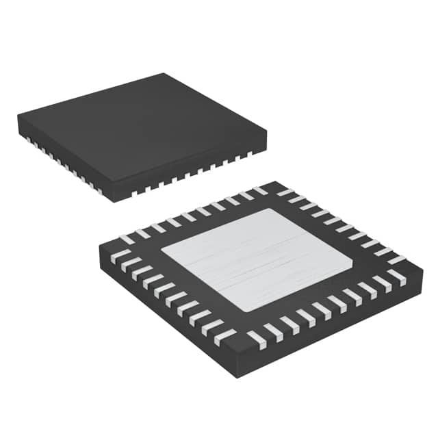
- Part No.:
- MAX6955ATL+
- Manufacturer:
- Analog Devices Inc./Maxim Integrated
- Category:
- Display Drivers
- Package:
- 40-WFQFN Exposed Pad
- Datasheet:
-
 MAX6955ATL+.pdf
- Description:
- IC DRVR 7/14/16 SEGMENT 40TQFN
- Quantity:
- Payment:

- Shipping:

Inventory:1,345
Please send an inquiry. Send us your inquiry, and we will respond immediately.
Product details
Overview
MAX6955ATL+ from Maxim Integrated is a 40-pin TQFN-EP LED display driver with integrated I/O expander and key-scan controller, operating from 2.7V to 5.5V. It drives up to 16 digits of 7-segment, 8 digits of 14/16-segment, or 128 discrete LEDs; features 104-character ASCII font ROM, 16-step digit-by-digit brightness control, and automatic key-matrix scanning for up to 32 switches - deployed in panel meters and audio/video front panels.
For engineers reviewing the MAX6955ATL+ datasheet, MAX6955ATL+ pinout, MAX6955ATL+ application, or MAX6955ATL+ equivalent, this page delivers verified technical context, real-world drive capability, GPIO configuration logic, blink synchronization behavior, and validated alternatives for industrial display subsystem design.
Technical Context
The MAX6955ATL+ implements an I²C-compatible 2-wire interface (400kbps max) with auto-incrementing register addressing and slave address selection via AD0/AD1 pins (16 possible addresses). Its internal architecture integrates segment drivers (O0–O18), digit multiplexers, static RAM for dual-plane digit storage (P0/P1), and a programmable RC oscillator (1–8MHz) with dead-clock protection at 95kHz.
It combines three functional domains on-die: display control (segment current set by single external RSET, slew-rate limited to 11mA/µs), GPIO/key-scan (P0–P4 configurable as inputs with 75µA pullup, IRQ assertion on debounce), and blink timing (synchronized across multiple units via OSC_OUT push-pull output and BLINK open-drain clock).
Key Specifications
| Parameter | Value and Actual Design Meaning |
|---|---|
| Supply Voltage | 2.7V to 5.5V - supports direct connection to 3.3V or 5V system rails without level-shifting. |
| I²C Interface Speed | 400kbps - compatible with standard-mode I²C controllers; meets timing specs for tSU,STO ≥ 0.6µs and tBUF ≥ 1.3µs. |
| Segment Drive Capability | −48mA source (typ, V+ = 2.7V) - sets peak current via external RSET; enables driving high-Vf bicolor LEDs. |
| Brightness Control | 16-step digital PWM per digit - allows independent intensity tuning without external DAC or resistor networks. |
| Key-Scan Capacity | Up to 32-key matrix with n-key rollover and hardware debounce - eliminates need for MCU polling or external debouncing circuitry. |
| Operating Temperature | −40°C to +125°C - qualified for automotive cabin and industrial control panel environments. |
| Shutdown Current | 10µA (typ) - retains RAM contents during low-power sleep; enables battery-backed display retention. |
Pinout & Package
MAX6955ATL+ uses a 40-pin TQFN-EP package (6mm × 6mm, 0.5mm pitch) with exposed paddle thermally connected to GND. The EP pad must be soldered to a large ground plane for thermal performance and EMI reduction.
| Pin/Terminal | Circuit Role | Design Meaning |
|---|---|---|
| O0–O18 | Digit/segment drivers | O0–O7 sink cathode current (common-cathode displays); O0–O18 source anode current (common-anode segments); high-Z when unused. |
| P0–P3 | GPIO / key-scan inputs | Configurable as logic inputs with internal pullup; used as Key_A–Key_D in key-scan mode; support matrix row/column scanning. |
| P4/IRQ | GPIO / interrupt output | Functions as general-purpose I/O or active-low IRQ signal asserted after key debounce completion. |
| SDA, SCL | I²C bidirectional data/clock | Open-drain SDA requires external 4.7kΩ pullup; SCL is input-only; both tolerate 6V max voltage. |
| AD0, AD1 | Slave address inputs | Set 4-bit address bits A3–A0; each pin connects to GND/V+/SCL/SDA for 16 unique I²C addresses. |
| ISET | Segment current reference | Connects to GND via RSET; sets full-scale segment current (e.g., 20mA with ~1.2kΩ at 3.3V). |
| OSC, OSC_OUT | Internal oscillator control/sync | OSC accepts RC network (RSET/CSET) or external 1–8MHz clock; OSC_OUT provides buffered clock for multi-driver blink sync. |
| BLINK | Blink timing output | Open-drain output synchronized to blink phase; used to drive external timing circuits or indicator LEDs. |
Key Features
| Feature | Design Value |
|---|---|
| Integrated 104-character ASCII font ROM | Eliminates external character lookup table; supports 14-/16-segment displays with symbols (£, €, ¥, ↑, ↓) and DP control bit. |
| Dual-plane digit memory (P0/P1) | Enables true blinking without MCU intervention - alternate planes displayed on blink clock edges; supports per-digit blink state. |
| Slew-rate-limited segment drivers | Reduces EMI emissions by limiting di/dt; measured at 11mA/µs - meets Class B radiated emission requirements in compact enclosures. |
| Hardware key-scan engine | Scans up to 32 keys with automatic n-key rollover and digital debounce; frees MCU resources and ensures consistent response time. |
| Digit-by-digit brightness control | 16-step PWM per digit register - enables dynamic contrast adjustment (e.g., dim leading zeros, bright status indicators) without software overhead. |
Applications
| Panel Meters | Audio/Video Front Panels |
|---|---|
Use Scenario: Digital readout of voltage, current, or temperature in DIN-rail mounted instrumentation. IC Role / Device Role / Timing Role: Primary display controller managing 8-digit 7-segment output and 4-button user interface. Use Value: Single-chip integration reduces BOM count; 125°C rating ensures reliability in enclosed metal cabinets with ambient heat buildup. |
Use Scenario: Source selection, volume, and playback status display on AV receivers and streaming devices. IC Role / Device Role / Timing Role: Drives mixed 14-segment alphanumeric + 7-segment bar graph using dual-plane blink for mute/standby indicators. Use Value: Built-in ASCII font and segment-level control enable rapid UI iteration without firmware font updates or GPIO reassignment. |
| White Goods Control Panels | Industrial Set-Top Boxes |
Use Scenario: Oven timer, cycle status, and temperature setting on kitchen appliance touch panels. IC Role / Device Role / Timing Role: Interfaces microcontroller to 16-segment display and membrane keypad matrix (24 keys). Use Value: Hardware key-scan with IRQ offloads real-time button handling; shutdown mode draws only 10µA during standby. |
Use Scenario: Channel number, signal strength, and menu navigation display in cable/satellite STBs. IC Role / Device Role / Timing Role: Drives 12-digit 7-segment display with independent brightness per digit and synchronized blink across dual-display units. Use Value: OSC_OUT and BLINK pins allow precise blink alignment between front-panel and remote-display modules without software coordination. |
Availability
MAX6955ATL+ is available at Aetrix Electronics and suitable for panel meters, audio/video front panels, white goods control interfaces, and industrial set-top boxes requiring stable component supply across extended temperature ranges.
Supply support for MAX6955ATL+ includes scheduled delivery planning, volume procurement assistance, BOM continuity management, traceable sourcing, and lifecycle availability coordination for OEM customers, industrial embedded developers, connected-device designers, and electronics production programs.
Manufacturer
Maxim Integrated (now part of Analog Devices) designs precision analog and mixed-signal ICs for industrial, automotive, and communications applications - emphasizing integration, reliability, and thermal robustness.
The MAX6955 product line targets embedded display subsystems requiring minimal MCU intervention, combining LED driving, key scanning, and I/O expansion in a single package rated for −40°C to +125°C operation.
FAQ
What is the function of the OSC and OSC_OUT pins on the MAX6955ATL+?
The OSC pin accepts either an external 1–8MHz CMOS clock or an RC network (RSET/CSET) to configure the internal multiplex oscillator. OSC_OUT provides a buffered copy of that clock in push-pull format, enabling precise blink synchronization across multiple MAX6955ATL+ devices without external timing components.
How does the MAX6955ATL+ handle key-switch debouncing?
The MAX6955ATL+ performs hardware-based key debouncing internally: it samples P0–P3 inputs at the OSC frequency, applies digital filtering, and asserts the P4/IRQ pin only after stable key closure detection. This eliminates software debounce routines and guarantees consistent 20ms minimum debounce time across all keys.
Can the MAX6955ATL+ drive both common-anode and common-cathode LED displays?
Yes - the MAX6955ATL+ supports both topologies: O0–O7 act as current sinks for common-cathode digit drivers, while O0–O18 act as current sources for common-anode segment drivers. Configuration is determined by display wiring and digit-type register settings, not by hardware revision.
What is the role of the dual-plane digit memory (P0 and P1) in the MAX6955ATL+?
The dual-plane digit memory enables autonomous blinking: when blink mode is enabled, the MAX6955ATL+ alternately displays data from P0 and P1 on successive blink clock cycles. Writing different characters (e.g., 'A' to P0, blank to P1) creates visible blink effects without CPU involvement or register updates.
How is segment current calibrated on the MAX6955ATL+?
Segment current is set by connecting the ISET pin to GND through a single external resistor RSET. For example, a 1.2kΩ resistor yields ~20mA segment source current at V+ = 3.3V. The relationship is linear and specified across 2.7V–5.5V supply range, with ±5% matching between outputs.
MAX6955ATL+ Specifications
- Product attributes
- Attribute value
- Manufacturer:
- Analog Devices Inc./Maxim Integrated
- Series:
- -
- Package/Case:
- 40-WFQFN Exposed Pad
- Packaging:
- Tube
- Product Status:
- Active
- Display Type:
- LED
- Configuration:
- 7, 14, 16 Segment
- Interface:
- I2C
- Digits or Characters:
- -
- Current - Supply:
- 22 mA
- Voltage - Supply:
- 2.7V ~ 5.5V
- Operating Temperature:
- -40°C ~ 125°C
- Grade:
- -
- Qualification:
- -
- Mounting Type:
- Surface Mount
- Supplier Device Package:
- 40-TQFN (6x6)
MAX6955ATL+ FAQ
1.How can I place an order for MAX6955ATL+ through Aetrix?
Please submit a Request for Quotation (RFQ) for MAX6955ATL+ on Aetrix. Our sales agent will provide a competitive quotation and guide you through the order confirmation once you accept the terms.
2.Are the price and stock information for MAX6955ATL+ reliable?
The price and inventory of MAX6955ATL+ are updated periodically and may fluctuate due to market conditions. Stock and pricing data are typically refreshed every 24 hours. Quotation validity for MAX6955ATL+ is usually 5 days.
3.What payment methods are accepted for MAX6955ATL+?
We accept Wire Transfer, PayPal, Credit Card, Western Union, MoneyGram, and Escrow for MAX6955ATL+ transactions.
Note: Certain payment methods may incur a processing fee.
4.How is shipping managed for MAX6955ATL+?
MAX6955ATL+ orders can be shipped via leading logistics carriers, including DHL, UPS, FedEx, TNT, or Registered Mail.
Once your MAX6955ATL+ order is processed, you will receive an email with the shipment details and tracking number.
Note: Tracking information may take up to 24 hours to appear. Express delivery typically takes 3–5 business days.
5.How can I obtain technical support or documentation for MAX6955ATL+?
For technical support, including MAX6955ATL+ datasheets, pinout diagrams, or application guidance, please contact our engineering support team. They can provide detailed documentation and assistance for your MAX6955ATL+ requirements.
6.How does Aetrix verify that MAX6955ATL+ is sourced from the original manufacturer or authorized distributors?
All MAX6955ATL+ products on Aetrix are procured from qualified distributors and authorized channels. Our dedicated quality assurance team conducts strict verification, including traceability checks and, if necessary, third-party testing. This ensures that MAX6955ATL+ meets industry standards.
7.What is the process for return or replacement of MAX6955ATL+?
All MAX6955ATL+ units undergo pre-shipment inspection (PSI). If there is an issue with MAX6955ATL+, returns or replacements are accepted under the following conditions:
1.Quantity discrepancies, incorrect items, or visible external defects (such as breakage or corrosion), acknowledged by Aetrix.
2.The issue is reported within 90 days of delivery.
3.The MAX6955ATL+ part is unused and in its original packaging.
Return procedure for MAX6955ATL+:
1.Submit a request within 90 days.
2.Obtain a Return Material Authorization (RMA) from Aetrix.
MAX6955ATL+ Tags

-
PCA8561AHN/AY
NXP Semiconductors

-
SN74LS47N
Texas Instruments

-
PCF85176T/1Y
NXP Semiconductors
-
PCF85176H/1,518
NXP Semiconductors

-
BU9796AMUV-E2
Rohm Semiconductor
-
PCA85176H/Q900/1,5
NXP Semiconductors
-
PCF8537AH/1,518
NXP Semiconductors

-
LM3914VX/NOPB
Texas Instruments

-
PCF85134HL/1,118
NXP Semiconductors

-
AS1115-BSST
ams-OSRAM USA INC.
-
PCA8534AH/Q900/1,5
NXP Semiconductors
-
LM3914V/NOPB
Texas Instruments
Tech Hub

A practical engineering guide to 3.3V and 5V logic compatibility, input thresholds, resistor dividers, translator ICs, MOSFET level shifting, I2C pull-ups, timing limits and power-sequencing risks.

The 74HC595 uses push-pull logic outputs, while the TPIC6B595 uses 50 V open-drain DMOS sinks for higher-power loads. This guide compares timing, current limits, 3.3 V interfacing, load wiring, thermal…

The 74HC595 converts serial data into eight stable parallel outputs. This guide covers pin functions, shift and storage timing, OE and MR behavior, drive-current limits, cascading, voltage compatibilit…

A technical comparison of level-sensitive latches and edge-triggered flip-flops, covering timing windows, setup and hold limits, master–slave operation, time borrowing, race-through, HDL inference and…

A D latch stores one bit while Enable controls when data can pass. This reference covers gate-level operation, truth tables, transparency, setup and hold timing, LE versus OE, common ICs and practical …

An SR latch stores one bit through cross-coupled feedback. This engineering reference covers NOR and NAND implementations, truth tables, forbidden-state recovery, gated operation, switch debouncing, fa…

Latch circuits retain one bit through feedback. This technical reference covers SR and D latches, truth tables, transparency, timing limits, latch-versus-flip-flop behavior, applications and common log…

An engineering guide to LED driver operation, constant-current and constant-voltage outputs, linear and switching topologies, dimming, IC selection, calculations, replacement compatibility, and fault c…

Operational amplifier guide covering op amp basics, feedback, ideal vs real op amps, common configurations, buffer circuits, offset, bias current, gain-bandwidth, slew rate, rail-to-rail limits and sel…

Jumper cables guide covering safe connection order, red and black clamp placement, final ground connection, cable gauge, length, clamp quality, copper vs CCA cables, jump starter comparison and battery…


