
 My Inquiry
 My Account


Analog Devices Inc./Maxim Integrated MAX6958BAEE+T
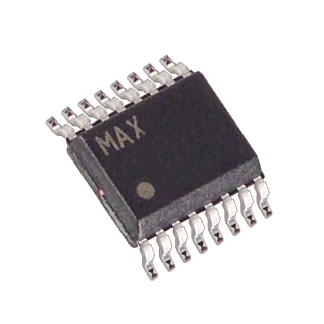
- Part No.:
- MAX6958BAEE+T
- Manufacturer:
- Analog Devices Inc./Maxim Integrated
- Category:
- Display Drivers
- Package:
- 16-SSOP (0.154", 3.90mm Width)
- Datasheet:
-
 MAX6958BAEE+T.pdf
- Description:
- IC DRVR 7 SEGMNT 4 DIGIT 16QSOP
- Quantity:
- Payment:

- Shipping:

Inventory:2,579
Please send an inquiry. Send us your inquiry, and we will respond immediately.
Product details
Overview
MAX6958BAEE+T from Maxim Integrated is a 2-wire SMBus/I²C-compatible LED display driver for common-cathode 7-segment digits, supporting up to four 9-segment digits plus four discrete LEDs or 36 discrete LEDs total. It features 23mA constant-current segment drive, 64-step digital brightness control, and operates from 3V to 5.5V across –40°C to +125°C - used in automotive panel meters and industrial control front panels.
For engineers reviewing the MAX6958BAEE+T datasheet, MAX6958BAEE+T pinout, MAX6958BAEE+T application, or MAX6958BAEE+T equivalent, this page delivers verified functional identity, automotive-grade thermal specs, I²C timing compliance (400kbps), segment current matching (±4%), and confirmed QSOP-16 package mapping - all validated against Maxim's official datasheet Rev 1 (11/05).
Technical Context
The MAX6958BAEE+T implements a fixed 4-digit multiplexed scan architecture with internal hexadecimal font decode logic and static RAM per digit. Its segment drivers are slew-rate-limited (11mA/µs) to suppress EMI, and it uses fixed 0.8V/2.1V logic thresholds on SDA/SCL for robust 2.5V/3.3V system interfacing while powered from 5V.
Unlike the MAX6959, the MAX6958BAEE+T lacks INPUT1/INPUT2 keyscan ports and IRQ functionality; its SEG9 pin is dedicated to segment output only. The device enters low-power shutdown (20µA) with data retention and supports scan-limit register configuration for 1–4 digit display control.
Key Specifications
| Parameter | Value and Actual Design Meaning |
|---|---|
| Supply Voltage Range | 3V to 5.5V - enables direct interface with 3.3V microcontrollers and 5V LED anode supplies without level shifters. |
| Segment Drive Current | 23mA typical peak - sets consistent brightness across segments without external current-setting resistors. |
| Brightness Control | 64-step digital adjustment - allows precise luminance tuning via I²C register write, independent of supply or temperature drift. |
| Scan Rate | 510–1050Hz - ensures flicker-free display at full 4-digit operation across full automotive temperature range. |
| I²C Speed | 400kbps - meets Fast-mode I²C specification, enabling high-throughput display updates in real-time HMI systems. |
| Operating Temperature | –40°C to +125°C - fully specified for under-hood automotive and industrial control environments. |
| Current Matching | ±4% segment-to-segment - minimizes visible intensity variation between digits and segments in multi-digit displays. |
Pinout & Package
MAX6958BAEE+T is housed in a 16-pin QSOP package (package code E16-1), with 3.9mm × 4.9mm body, 1.27mm pitch, and exposed pad not electrically connected. Pin 1 is SDA; pin 2 is SCL; pins 4–7 and 11–15 serve dual-function DIG/SEG outputs; pin 8 is GND; pin 16 is V+.
| Pin/Terminal | Circuit Role | Design Meaning |
|---|---|---|
| SDA (Pin 1) | Open-drain bidirectional serial data line | Requires external 4.7kΩ pullup to V+; supports SMBus timeout and arbitration in multi-master systems. |
| SCL (Pin 2) | CMOS input clock line | Accepts 0.8V/2.1V logic thresholds - compatible with 2.5V/3.3V controllers even when V+ = 5V. |
| DIG0/SEG0–DIG3/SEG3 (Pins 4–7, 11–15) | Digit cathode sink / segment anode source drivers | Each pin operates in dual mode: sinks current from digit cathodes or sources current to segment anodes (23mA max). |
| SEG9 (Pin 3) | Dedicated 9th segment output | Fixed as segment driver only - no interrupt or GPIO function (distinguishes MAX6958 from MAX6959). |
| GND (Pin 8) | Power and signal reference ground | Must be low-impedance connection; shared return path for all segment/digit currents. |
| V+ (Pin 16) | Positive supply input | Supplies both logic core and LED drivers; decoupling capacitor (0.1µF) required within 1cm of pin. |
Key Features
| Feature | Design Value |
|---|---|
| Hexadecimal decode/no-decode per digit | Enables mixed-mode display: numeric digits use built-in 0–F font while bar graphs or custom symbols use direct segment control. |
| Slew-rate-limited segment drivers | 11mA/µs dI/dt reduces radiated EMI by >10dB in 30–200MHz band - critical for automotive EMC compliance. |
| 20µA shutdown with data retention | Preserves digit/segment register contents during sleep; wake-up requires only configuration register write - no reinitialization overhead. |
| Scan-limit register (1–4 digits) | Adjusts multiplex ratio dynamically to maintain constant perceived brightness when fewer than four digits are active. |
| Automotive-grade qualification | Specified over –40°C to +125°C with AEC-Q100 stress test alignment - suitable for dashboard instrumentation and engine control HMI. |
Applications
| Automotive Panel Meters | Industrial Control Front Panels |
|---|---|
Use Scenario: Real-time display of vehicle battery voltage, coolant temperature, and oil pressure in instrument clusters. IC Role / Device Role / Timing Role: LED display driver handling multiplexed 4-digit numeric output with automatic decimal point positioning and brightness scaling based on ambient light. Use Value: Eliminates microcontroller GPIO overhead and PWM timing constraints; 23mA drive ensures visibility under direct sunlight. |
Use Scenario: Operator interface on PLC-mounted HMIs showing process setpoints, status codes, and alarm counters. IC Role / Device Role / Timing Role: Dedicated display controller managing up to 36 discrete LEDs for status indicators and 4-digit numeric readouts via single I²C bus. Use Value: Reduces firmware complexity and PCB routing density; 400kbps I²C allows <10ms full-display refresh at 20ms system polling intervals. |
| White Goods Control Boards | Audio/Video Equipment Displays |
Use Scenario: Oven timer, microwave power level, and washer cycle progress shown on embedded LED displays. IC Role / Device Role / Timing Role: Low-power display interface with shutdown mode activated during standby to meet Energy Star standby current limits. Use Value: 20µA shutdown current meets <50µA system-level standby targets; 64-step brightness enables seamless dimming from daylight to night mode. |
Use Scenario: Channel number, volume level, and input source indication on AV receivers and soundbars. IC Role / Device Role / Timing Role: I²C-connected display driver synchronized to audio subsystem interrupts for glitch-free updates during playback. Use Value: Slew-rate limiting prevents audible noise coupling into analog audio paths; 3V–5.5V operation supports mixed-voltage board designs. |
Equivalent & Alternatives
The following parts are listed as comparable options for similar LED display driver applications.
| Alternative Part | Technical Difference | Application Difference | Selection Advice |
|---|---|---|---|
| MAX6959BAEE+T | Includes INPUT1/INPUT2 keyscan ports and configurable IRQ/SEG9 pin; identical LED drive capability and package. | Required when matrix keypad scanning (up to 8 switches) is needed alongside display driving. | Select MAX6959BAEE+T only if keyscan functionality is required - MAX6958BAEE+T offers lower cost and simpler firmware for display-only use cases. |
| TLC59283DBQR | 16-channel constant-current sink driver (no digit multiplexing or font decode); 15–120mA adjustable per channel; SPI interface only. | Suitable for discrete LED arrays or bar graphs but cannot drive multiplexed 7-segment digits natively. | Choose TLC59283DBQR for high-current discrete LED control where segment decoding and digit multiplexing are handled in firmware. |
Compared with MAX6959BAEE+T, the MAX6958BAEE+T removes keyscan hardware to reduce cost and firmware complexity; compared with TLC59283DBQR, it integrates multiplex control and font decode but trades off per-channel current flexibility and SPI compatibility.
Availability
MAX6958BAEE+T is available at Aetrix Electronics and suitable for automotive panel meters, industrial control front panels, and white goods control boards requiring stable component supply across extended temperature ranges and long production lifecycles.
Supply support for MAX6958BAEE+T includes scheduled delivery planning, volume procurement assistance, BOM continuity management, traceable sourcing, and lifecycle availability coordination for OEM customers, industrial embedded developers, connected-device designers, and electronics production programs.
Manufacturer
Maxim Integrated (now part of Analog Devices) designs precision analog, mixed-signal, and power management ICs for demanding industrial, automotive, and communications applications.
The MAX6958 belongs to Maxim's LED display driver product line, engineered specifically for reliable, low-firmware-overhead interface between microcontrollers and multiplexed common-cathode LED displays in harsh environments.
FAQ
What is the primary function of the MAX6958BAEE+T?
The MAX6958BAEE+T is a dedicated 4-digit, 9-segment common-cathode LED display driver with integrated I²C/SMBus interface, constant-current segment drivers (23mA), and 64-step digital brightness control. It handles multiplexing, font decoding, and segment current regulation - offloading these tasks from the host microcontroller. Its design eliminates the need for external transistors, resistors, or timing-critical firmware loops in LED display systems.
Does the MAX6958BAEE+T support keyswitch scanning like the MAX6959?
No, the MAX6958BAEE+T does not support keyswitch scanning. Unlike the MAX6959, it lacks INPUT1 and INPUT2 pins and has no IRQ output or keyscan registers. Its SEG9 pin is fixed as a segment driver only. Keyscan functionality is exclusive to the MAX6959 family; using MAX6958BAEE+T requires external GPIO or a separate keyscan IC if switch reading is needed.
What package type and footprint does the MAX6958BAEE+T use?
The MAX6958BAEE+T is supplied in a 16-pin QSOP package (package code E16-1), measuring 3.9mm × 4.9mm with 1.27mm lead pitch. It is pin-compatible with the MAX6958AAEE and MAX6959BAEE+T in the same package. The exposed pad is non-functional and may be left unconnected or tied to GND for mechanical stability - no thermal or electrical benefit is gained from soldering it.
Can the MAX6958BAEE+T drive bicolor dual-digit LED displays?
Yes, the MAX6958BAEE+T can drive bicolor dual-digit LED displays by treating each color as a separate digit. For example, red segments connect to DIG0/SEG0–DIG1/SEG1 and green segments to DIG2/SEG2–DIG3/SEG3. The device's dual-mode DIG/SEG pins allow independent control of cathode selection and segment activation, supporting full-color digit pairing without external demultiplexing logic.
How does the MAX6958BAEE+T handle display brightness consistency across temperature?
The MAX6958BAEE+T maintains brightness consistency through its 64-step digital brightness control register and matched segment current sources (±4% matching). While forward voltage of LEDs varies with temperature, the device's constant-current architecture ensures stable segment current regardless of VLED drift. Combined with its –40°C to +125°C guaranteed operation, this provides predictable luminance in automotive and industrial environments without closed-loop optical feedback.
MAX6958BAEE+T Specifications
- Product attributes
- Attribute value
- Manufacturer:
- Analog Devices Inc./Maxim Integrated
- Series:
- -
- Package/Case:
- 16-SSOP (0.154", 3.90mm Width)
- Packaging:
- Tape & Reel (TR)
- Product Status:
- Active
- Display Type:
- LED
- Configuration:
- 7 Segment + 2 Annunciators
- Interface:
- SMBus (2-Wire/I2C)
- Digits or Characters:
- 4 Digits
- Current - Supply:
- 5.9 mA
- Voltage - Supply:
- 3V ~ 5.5V
- Operating Temperature:
- -40°C ~ 125°C
- Grade:
- -
- Qualification:
- -
- Mounting Type:
- Surface Mount
- Supplier Device Package:
- 16-QSOP
MAX6958BAEE+T FAQ
1.How can I place an order for MAX6958BAEE+T through Aetrix?
Please submit a Request for Quotation (RFQ) for MAX6958BAEE+T on Aetrix. Our sales agent will provide a competitive quotation and guide you through the order confirmation once you accept the terms.
2.Are the price and stock information for MAX6958BAEE+T reliable?
The price and inventory of MAX6958BAEE+T are updated periodically and may fluctuate due to market conditions. Stock and pricing data are typically refreshed every 24 hours. Quotation validity for MAX6958BAEE+T is usually 5 days.
3.What payment methods are accepted for MAX6958BAEE+T?
We accept Wire Transfer, PayPal, Credit Card, Western Union, MoneyGram, and Escrow for MAX6958BAEE+T transactions.
Note: Certain payment methods may incur a processing fee.
4.How is shipping managed for MAX6958BAEE+T?
MAX6958BAEE+T orders can be shipped via leading logistics carriers, including DHL, UPS, FedEx, TNT, or Registered Mail.
Once your MAX6958BAEE+T order is processed, you will receive an email with the shipment details and tracking number.
Note: Tracking information may take up to 24 hours to appear. Express delivery typically takes 3–5 business days.
5.How can I obtain technical support or documentation for MAX6958BAEE+T?
For technical support, including MAX6958BAEE+T datasheets, pinout diagrams, or application guidance, please contact our engineering support team. They can provide detailed documentation and assistance for your MAX6958BAEE+T requirements.
6.How does Aetrix verify that MAX6958BAEE+T is sourced from the original manufacturer or authorized distributors?
All MAX6958BAEE+T products on Aetrix are procured from qualified distributors and authorized channels. Our dedicated quality assurance team conducts strict verification, including traceability checks and, if necessary, third-party testing. This ensures that MAX6958BAEE+T meets industry standards.
7.What is the process for return or replacement of MAX6958BAEE+T?
All MAX6958BAEE+T units undergo pre-shipment inspection (PSI). If there is an issue with MAX6958BAEE+T, returns or replacements are accepted under the following conditions:
1.Quantity discrepancies, incorrect items, or visible external defects (such as breakage or corrosion), acknowledged by Aetrix.
2.The issue is reported within 90 days of delivery.
3.The MAX6958BAEE+T part is unused and in its original packaging.
Return procedure for MAX6958BAEE+T:
1.Submit a request within 90 days.
2.Obtain a Return Material Authorization (RMA) from Aetrix.
MAX6958BAEE+T Tags

-
PCA8561AHN/AY
NXP Semiconductors

-
SN74LS47N
Texas Instruments

-
PCF85176T/1Y
NXP Semiconductors
-
PCF85176H/1,518
NXP Semiconductors

-
BU9796AMUV-E2
Rohm Semiconductor
-
PCA85176H/Q900/1,5
NXP Semiconductors
-
PCF8537AH/1,518
NXP Semiconductors

-
LM3914VX/NOPB
Texas Instruments

-
PCF85134HL/1,118
NXP Semiconductors

-
AS1115-BSST
ams-OSRAM USA INC.
-
PCA8534AH/Q900/1,5
NXP Semiconductors
-
LM3914V/NOPB
Texas Instruments
Tech Hub

A practical engineering guide to 3.3V and 5V logic compatibility, input thresholds, resistor dividers, translator ICs, MOSFET level shifting, I2C pull-ups, timing limits and power-sequencing risks.

The 74HC595 uses push-pull logic outputs, while the TPIC6B595 uses 50 V open-drain DMOS sinks for higher-power loads. This guide compares timing, current limits, 3.3 V interfacing, load wiring, thermal…

The 74HC595 converts serial data into eight stable parallel outputs. This guide covers pin functions, shift and storage timing, OE and MR behavior, drive-current limits, cascading, voltage compatibilit…

A technical comparison of level-sensitive latches and edge-triggered flip-flops, covering timing windows, setup and hold limits, master–slave operation, time borrowing, race-through, HDL inference and…

A D latch stores one bit while Enable controls when data can pass. This reference covers gate-level operation, truth tables, transparency, setup and hold timing, LE versus OE, common ICs and practical …

An SR latch stores one bit through cross-coupled feedback. This engineering reference covers NOR and NAND implementations, truth tables, forbidden-state recovery, gated operation, switch debouncing, fa…

Latch circuits retain one bit through feedback. This technical reference covers SR and D latches, truth tables, transparency, timing limits, latch-versus-flip-flop behavior, applications and common log…

An engineering guide to LED driver operation, constant-current and constant-voltage outputs, linear and switching topologies, dimming, IC selection, calculations, replacement compatibility, and fault c…

Operational amplifier guide covering op amp basics, feedback, ideal vs real op amps, common configurations, buffer circuits, offset, bias current, gain-bandwidth, slew rate, rail-to-rail limits and sel…

Jumper cables guide covering safe connection order, red and black clamp placement, final ground connection, cable gauge, length, clamp quality, copper vs CCA cables, jump starter comparison and battery…


