
 My Inquiry
 My Account


Analog Devices Inc./Maxim Integrated MAX6960AMH+D
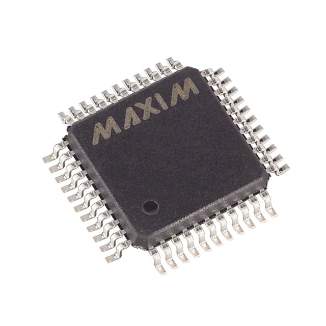
- Part No.:
- MAX6960AMH+D
- Manufacturer:
- Analog Devices Inc./Maxim Integrated
- Category:
- Display Drivers
- Package:
- 44-QFP
- Datasheet:
-
 MAX6960AMH+D.pdf
- Description:
- IC DRVR MATRIX 8X8 44MQFP
- Quantity:
- Payment:

- Shipping:

Inventory:3,613
Please send an inquiry. Send us your inquiry, and we will respond immediately.
Product details
Overview
MAX6960AMH+D from Maxim Integrated is a 4-wire serially interfaced, cathode-row LED display driver for 8 × 8 matrix displays. It supports two monocolor or one RGY (red/green/yellow) display with 2- or 4-step pixel-level intensity control, 256-step global panel brightness, and analog/digital digit-by-digit current calibration. Designed for indoor signage and message boards, it operates from 2.7V–3.6V and delivers up to 40mA peak segment current per digit.
For engineers reviewing the MAX6960AMH+D datasheet, MAX6960AMH+D pinout, MAX6960AMH+D application, or MAX6960AMH+D equivalent, key selection considerations include its 44-pin MQFP package, dual-digit RGY support, open/short LED fault detection, local 3-wire address bus for daisy-chained configurations, and compatibility with 20MHz high-speed serial interface timing.
Technical Context
The MAX6960AMH+D implements frame-modulated pixel intensity using a 12-frame superframe to deliver arithmetic (off, 1/3, 2/3, full) or geometric (off, 1/4, 1/2, full) 4-level per-pixel control. Its architecture enables memory-mapped display planes across up to 256 daisy-chained drivers via ADDIN/ADDOUT/ADDCLK, with automatic address allocation and global command broadcast.
It features dual RISET pins (RISET0/RISET1) enabling independent 20mA or 40mA peak segment current programming per digit-either fixed via GND/open or adjustable via external resistors-and integrates slew-rate-limited segment drivers to reduce EMI while supporting burst white mode and plane-switching intervals from 63Hz to one change per 63 seconds.
Key Specifications
| Parameter | Value and Actual Design Meaning |
|---|---|
| Supply Voltage | 2.7V to 3.6V - Enables direct operation from standard 3.3V logic rails with minimal headroom loss across output stages. |
| Peak Segment Current | 40mA (digit 0 or 1) - Configurable per digit via RISET0/RISET1; supports 5mA average per LED in 1:8 multiplexed 8×8 displays. |
| Serial Interface Speed | 20MHz - High-speed 4-wire SPI-compatible interface (CS/DIN/CLK/DOUT) for rapid display memory updates. |
| Display Memory Planes | 2 or 4 planes - Supports animation buffering: 2 planes at 2-bits-per-pixel (32 bytes each), 4 planes at 1-bit-per-pixel (16 bytes each). |
| Intensity Resolution | 256-step global PWM + 4-step per-pixel - Enables fade effects, background lighting compensation, and 16-color RGY rendering. |
| Fault Detection | Open/short LED detection - Monitors all 128 segments (8 rows × 16 columns) and reports faults via status register. |
| Operating Temperature | −40°C to +125°C - Qualified for industrial and automotive-grade embedded signage applications. |
Pinout & Package
MAX6960AMH+D uses a 44-pin MQFP (Metric Quad Flat Package) with exposed pad (EP), requiring connection of EP to GND for thermal and electrical integrity. The package supports surface-mount assembly and provides 16 anode column drivers (COL1–COL16), 8 cathode row sinks (ROW1–ROW8), and dedicated address/data bus pins for multi-driver synchronization.
| Pin/Terminal | Circuit Role | Design Meaning |
|---|---|---|
| ROW1–ROW8 | Cathode sink outputs | Drive display rows by sinking up to 750mA total; enable multiplexed scanning of 8×8 matrices. |
| COL1–COL16 | Anode source outputs | Source up to 48mA total; drive 16 columns across two monocolor digits or red/green sub-arrays of RGY digit. |
| RISET0 / RISET1 | Digit current setting inputs | Set digit 0 or digit 1 segment current to 20mA (open) or 40mA (GND); enable resistor-based fine-tuning between values. |
| ADDIN / ADDOUT / ADDCLK | Local 3-wire address bus | Enable automatic memory map allocation across daisy-chained drivers; ADDOUT doubles as plane-change interrupt output. |
| CS / DIN / CLK / DOUT | 4-wire serial interface | Supports global command broadcast and individual register access; DOUT is tri-state for bus sharing. |
Key Features
| Feature | Design Value |
|---|---|
| Digit-by-digit current calibration | Analog (RISET resistors) and digital (256-step scaling) adjustment per digit enables batch-to-batch LED color matching on RGY panels. |
| Multiplane animation engine | Hardware-managed plane switching from 63Hz to one frame per 63s eliminates software timing dependency during display updates. |
| Slew-rate-limited drivers | Controlled ∆ISEG/∆t = 30mA/µs reduces EMI and avoids supply rail collapse during fast column switching. |
| Global command broadcast | Single write operation synchronizes intensity, shutdown, or plane select across all interconnected MAX6960AMH+D devices. |
| LED open/short detection | Automatically identifies failed segments and reports status via fault register-no external sensing circuitry required. |
Applications
| Indoor Message Boards | Gaming Machine Displays |
|---|---|
Use Scenario: Dynamic text and icon updates on wall-mounted or kiosk-based information panels in retail, transit, or facility environments. IC Role / Device Role / Timing Role: Primary LED matrix controller managing 8×8 RGY pixels with real-time intensity grading and fault-aware refresh cycles. Use Value: 256-step global PWM enables ambient light-adaptive brightness; built-in plane switching simplifies scrolling animation without CPU intervention. |
Use Scenario: Animated symbol reels and status indicators on slot machines, video poker terminals, and arcade cabinets. IC Role / Device Role / Timing Role: Graphics driver for multicolumn monocolor or RGY dot-matrix displays, synchronized across multiple MAX6960AMH+D units via ADD bus. Use Value: Four-step per-pixel intensity allows distinct symbol states (e.g., "win", "bonus", "jackpot") with color-shade differentiation on RGY panels. |
| Industrial Control Panels | Audio/Video Equipment UI |
Use Scenario: Operator interface displays on PLCs, HMIs, and test equipment requiring high reliability and wide temperature operation. IC Role / Device Role / Timing Role: Fault-resilient LED driver with open/short detection and −40°C to +125°C operation for harsh factory-floor environments. Use Value: Local 3-wire address bus ensures deterministic memory mapping across up to 256 drivers-critical for large-scale panel scalability. |
Use Scenario: Front-panel status indicators, channel meters, and menu navigation elements on AV receivers, mixers, and studio monitors. IC Role / Device Role / Timing Role: Low-power display controller driving small-format monocolor 8×8 digits with precise intensity gradation and zero-software-timing overhead. Use Value: Shutdown mode draws only 600µA while retaining full display memory-ideal for standby-aware consumer electronics. |
Equivalent & Alternatives
The following parts are listed as comparable options for similar LED display driver applications.
| Alternative Part | Technical Difference | Application Difference | Selection Advice |
|---|---|---|---|
| MAX6962AMH+ | Supports monocolor or RGY displays with 2- or 4-step intensity; lacks RGY-specific configuration bits (C bit fixed at 0) and excludes RGB capability. | Optimized for monocolor-only panels where RGY color mixing is unnecessary; no RGY memory mapping flexibility. | Select MAX6962AMH+ when driving single-color signs with identical intensity requirements but lower firmware complexity. |
| MAX6961AMH+ | Supports monocolor or RGY with 2-step intensity only; PI bit fixed at 0 disables 2-bits-per-pixel mode and limits display memory to 4 planes of 16 bytes. | Suitable for basic on/off or dual-intensity messaging-insufficient for multi-shade RGY graphics or smooth fades. | Choose MAX6961AMH+ for cost-sensitive, low-complexity applications where 4-level per-pixel control is not required. |
Compared with MAX6962AMH+ and MAX6961AMH+, the MAX6960AMH+ uniquely supports full RGY 2-bits-per-pixel operation with configurable C/PI bits, enabling 16-color rendering and flexible memory mapping-making it the only option among the three for advanced RGY graphic signage requiring both color fidelity and animation depth.
Availability
MAX6960AMH+D is available at Aetrix Electronics and suitable for indoor message boards, gaming machine displays, and industrial control panels requiring stable component supply, long-term lifecycle support, and guaranteed traceable sourcing.
Supply support for MAX6960AMH+D includes scheduled delivery planning, volume procurement assistance, BOM continuity management, traceable sourcing, and lifecycle availability coordination for OEM customers, industrial embedded developers, connected-device designers, and electronics production programs.
Manufacturer
Maxim Integrated (now part of Analog Devices) designs precision analog, mixed-signal, and power management ICs for industrial, automotive, and communications systems.
The MAX6960AMH+D belongs to Maxim's high-efficiency LED display driver product line, engineered specifically for scalable, fault-aware, and animation-capable indoor signage with minimal host processor overhead.
FAQ
What display configurations does the MAX6960AMH+D support?
The MAX6960AMH+D supports two monocolor 8×8 matrix displays or one RGY 8×8 matrix display using its 8 cathode-row and 16 anode-column drivers. It enables 2- or 4-step per-pixel intensity control and 256-step global panel brightness. Configuration is set via the PI and C bits in the global panel configuration register, allowing flexible mapping for red/green sub-arrays in RGY mode.
How does the MAX6960AMH+D handle LED fault detection?
The MAX6960AMH+D performs automatic open-circuit and short-circuit detection across all 128 segments (8 rows × 16 columns). Detected faults are reported in the device's fault status register and can trigger an interrupt via the ADDOUT pin when used in daisy-chained configurations. No external components or host polling are required for basic fault reporting.
Can the MAX6960AMH+D drive RGB displays directly?
No, the MAX6960AMH+D cannot drive standard RGB displays directly due to blue LED forward voltage requirements (~3.5V–4.5V), exceeding its 2.7V–3.6V supply range. However, it can serve as the graphics controller for RGB panels when paired with external pass transistors-retaining all features including pixel-level intensity control and fault detection as described in Figure 17 of the datasheet.
What is the function of the RISET0 and RISET1 pins on the MAX6960AMH+D?
RISET0 and RISET1 configure the peak segment current for digit 0 and digit 1 independently: grounding selects 40mA, leaving open selects 20mA, and connecting via resistor enables analog trimming between those values. This allows per-digit current calibration for color matching on RGY displays or efficiency optimization across varying LED batches.
How does the MAX6960AMH+D manage display memory across multiple devices?
The MAX6960AMH+D uses a local 3-wire address bus (ADDIN/ADDOUT/ADDCLK) to automatically allocate contiguous memory map addresses across up to 256 daisy-chained devices. This allows the host to treat the entire panel as unified display memory planes-enabling seamless scrolling, animation, and global commands without manual address calculation or per-device register writes.
MAX6960AMH+D Specifications
- Product attributes
- Attribute value
- Manufacturer:
- Analog Devices Inc./Maxim Integrated
- Series:
- -
- Package/Case:
- 44-QFP
- Packaging:
- Tray
- Product Status:
- Active
- Display Type:
- LED
- Configuration:
- 8 x 8 (Matrix)
- Interface:
- 4-Wire Serial
- Digits or Characters:
- Any Digit Type
- Current - Supply:
- 7.5 mA
- Voltage - Supply:
- 2.7V ~ 3.6V
- Operating Temperature:
- -40°C ~ 125°C
- Grade:
- -
- Qualification:
- -
- Mounting Type:
- Surface Mount
- Supplier Device Package:
- 44-MQFP (10x10)
MAX6960AMH+D FAQ
1.How can I place an order for MAX6960AMH+D through Aetrix?
Please submit a Request for Quotation (RFQ) for MAX6960AMH+D on Aetrix. Our sales agent will provide a competitive quotation and guide you through the order confirmation once you accept the terms.
2.Are the price and stock information for MAX6960AMH+D reliable?
The price and inventory of MAX6960AMH+D are updated periodically and may fluctuate due to market conditions. Stock and pricing data are typically refreshed every 24 hours. Quotation validity for MAX6960AMH+D is usually 5 days.
3.What payment methods are accepted for MAX6960AMH+D?
We accept Wire Transfer, PayPal, Credit Card, Western Union, MoneyGram, and Escrow for MAX6960AMH+D transactions.
Note: Certain payment methods may incur a processing fee.
4.How is shipping managed for MAX6960AMH+D?
MAX6960AMH+D orders can be shipped via leading logistics carriers, including DHL, UPS, FedEx, TNT, or Registered Mail.
Once your MAX6960AMH+D order is processed, you will receive an email with the shipment details and tracking number.
Note: Tracking information may take up to 24 hours to appear. Express delivery typically takes 3–5 business days.
5.How can I obtain technical support or documentation for MAX6960AMH+D?
For technical support, including MAX6960AMH+D datasheets, pinout diagrams, or application guidance, please contact our engineering support team. They can provide detailed documentation and assistance for your MAX6960AMH+D requirements.
6.How does Aetrix verify that MAX6960AMH+D is sourced from the original manufacturer or authorized distributors?
All MAX6960AMH+D products on Aetrix are procured from qualified distributors and authorized channels. Our dedicated quality assurance team conducts strict verification, including traceability checks and, if necessary, third-party testing. This ensures that MAX6960AMH+D meets industry standards.
7.What is the process for return or replacement of MAX6960AMH+D?
All MAX6960AMH+D units undergo pre-shipment inspection (PSI). If there is an issue with MAX6960AMH+D, returns or replacements are accepted under the following conditions:
1.Quantity discrepancies, incorrect items, or visible external defects (such as breakage or corrosion), acknowledged by Aetrix.
2.The issue is reported within 90 days of delivery.
3.The MAX6960AMH+D part is unused and in its original packaging.
Return procedure for MAX6960AMH+D:
1.Submit a request within 90 days.
2.Obtain a Return Material Authorization (RMA) from Aetrix.
MAX6960AMH+D Tags

-
PCA8561AHN/AY
NXP Semiconductors

-
SN74LS47N
Texas Instruments

-
PCF85176T/1Y
NXP Semiconductors
-
PCF85176H/1,518
NXP Semiconductors

-
BU9796AMUV-E2
Rohm Semiconductor
-
PCA85176H/Q900/1,5
NXP Semiconductors
-
PCF8537AH/1,518
NXP Semiconductors

-
LM3914VX/NOPB
Texas Instruments

-
PCF85134HL/1,118
NXP Semiconductors

-
AS1115-BSST
ams-OSRAM USA INC.
-
PCA8534AH/Q900/1,5
NXP Semiconductors
-
LM3914V/NOPB
Texas Instruments
Tech Hub

A practical engineering guide to 3.3V and 5V logic compatibility, input thresholds, resistor dividers, translator ICs, MOSFET level shifting, I2C pull-ups, timing limits and power-sequencing risks.

The 74HC595 uses push-pull logic outputs, while the TPIC6B595 uses 50 V open-drain DMOS sinks for higher-power loads. This guide compares timing, current limits, 3.3 V interfacing, load wiring, thermal…

The 74HC595 converts serial data into eight stable parallel outputs. This guide covers pin functions, shift and storage timing, OE and MR behavior, drive-current limits, cascading, voltage compatibilit…

A technical comparison of level-sensitive latches and edge-triggered flip-flops, covering timing windows, setup and hold limits, master–slave operation, time borrowing, race-through, HDL inference and…

A D latch stores one bit while Enable controls when data can pass. This reference covers gate-level operation, truth tables, transparency, setup and hold timing, LE versus OE, common ICs and practical …

An SR latch stores one bit through cross-coupled feedback. This engineering reference covers NOR and NAND implementations, truth tables, forbidden-state recovery, gated operation, switch debouncing, fa…

Latch circuits retain one bit through feedback. This technical reference covers SR and D latches, truth tables, transparency, timing limits, latch-versus-flip-flop behavior, applications and common log…

An engineering guide to LED driver operation, constant-current and constant-voltage outputs, linear and switching topologies, dimming, IC selection, calculations, replacement compatibility, and fault c…

Operational amplifier guide covering op amp basics, feedback, ideal vs real op amps, common configurations, buffer circuits, offset, bias current, gain-bandwidth, slew rate, rail-to-rail limits and sel…

Jumper cables guide covering safe connection order, red and black clamp placement, final ground connection, cable gauge, length, clamp quality, copper vs CCA cables, jump starter comparison and battery…


