
 My Inquiry
 My Account


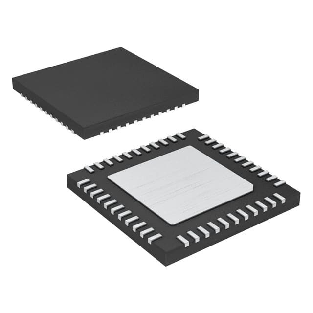
Analog Devices Inc./Maxim Integrated MAX6962ATH+
- Part No.:
- MAX6962ATH+
- Manufacturer:
- Analog Devices Inc./Maxim Integrated
- Category:
- Display Drivers
- Package:
- 44-WFQFN Exposed Pad
- Datasheet:
-
 MAX6962ATH+.pdf
- Description:
- IC DRVR LED 8X8 44-TQFN
- Quantity:
- Payment:

- Shipping:

Inventory:3,598
Please send an inquiry. Send us your inquiry, and we will respond immediately.
Product details
Overview
MAX6962ATH+ from Maxim Integrated is a 44-pin TQFN LED display driver IC for 8×8 cathode-row matrix displays, supporting monocolor or RGY configurations with two- or four-step pixel-level intensity control, 256-step global panel brightness, and open/short LED fault detection. It operates from 2.7V–3.6V, delivers up to 40mA peak segment current per digit, and interfaces via high-speed 20MHz 4-wire serial bus for industrial signage and message boards.
For engineers reviewing the MAX6962ATH+ datasheet, MAX6962ATH+ pinout, MAX6962ATH+ application, or MAX6962ATH+ equivalent, key selection considerations include its dual-digit current-setting pins (RISET0/RISET1), local 3-wire address allocation for daisy-chained drivers, analog/digital segment calibration, and support for 2-bit-per-pixel RGY color mixing - all critical for scalable LED panel design.
Technical Context
The MAX6962ATH+ implements frame-modulated 2-bit-per-pixel intensity control using 12-frame superframes with arithmetic (off, 1/3, 2/3, full) or geometric (off, 1/4, 1/2, full) scaling per pixel. Its architecture enables automatic memory mapping across up to 256 daisy-chained devices via ADDIN/ADDOUT/ADDCLK, with global command broadcast and plane-switching rates adjustable from 63Hz to one change every 63 seconds.
It integrates slew-rate-limited segment drivers to reduce EMI, supports burst white mode for memory plane initialization, and uses dead-clock protection with oscillator frequency monitoring (50–200kHz). The device features on-chip current calibration per digit (via RISET0/RISET1), open/short LED detection, and low-power shutdown with full data retention at -40°C to +125°C.
Key Specifications
| Parameter | Value and Actual Design Meaning |
|---|---|
| Supply Voltage | 2.7V to 3.6V - Enables direct operation from standard 3.3V logic rails with minimal headroom loss in LED drive path. |
| Peak Segment Current | 40mA (digit 0 or 1, configurable via RISET0/RISET1) - Supports high-brightness indoor LED panels with 5mA average per LED under 1:8 multiplexing. |
| Serial Interface Speed | 20MHz - Allows rapid update of multi-driver panels; 9.83 Mbps throughput for 24-bit direct addressing with 2-bit-per-pixel data. |
| Intensity Resolution | 256-step global PWM + 4-step per-pixel (2-bit) - Enables fade-in/fade-out effects and 16-color RGY display capability without host CPU overhead. |
| Operating Temperature | -40°C to +125°C - Qualified for industrial embedded systems and automotive-adjacent signage applications requiring extended thermal range. |
| Fault Detection | Open-circuit and short-circuit LED detection per segment - Reduces system-level diagnostic complexity and enables real-time display health monitoring. |
| Memory Architecture | 64 bytes total: 2 planes × 32 bytes (2-bit mode) or 4 planes × 16 bytes (1-bit mode) - Enables double-buffered animation with automatic plane switching and interrupt-driven updates. |
Pinout & Package
MAX6962ATH+ is housed in a 44-pin TQFN package with exposed pad (EP), measuring 7mm × 7mm × 0.8mm, rated for 2162mW continuous power dissipation at +70°C (derated 27mW/°C above).
| Pin/Terminal | Circuit Role | Design Meaning |
|---|---|---|
| GND (Pins 1,6,11,12,44) | Ground reference | Primary return path for ROW sink and COL source currents; EP must be soldered to PCB ground plane for thermal and EMI performance. |
| ROW1–ROW8 (Pins 2–5,7–10) | Cathode-row sink drivers | Eight constant-current sinks for LED cathodes; each supports up to 750mA total sink current across all active rows. |
| COL1–COL16 (Pins 19,20,21,23–27,29–33,35,36,37) | Anode-column source drivers | Sixteen constant-current sources (max 48mA each); collectively drive 8×8 monocolor or RGY matrices with column multiplexing. |
| V+ (Pins 22,28,34,38) | Positive supply input | Four dedicated V+ pins reduce IR drop; requires 47µF bulk + 0.1µF ceramic bypass per chip for stable 2.7–3.6V operation. |
| OSC (Pin 13) | Master clock input | Accepts 1–8.5MHz CMOS clock; internal dead-clock monitor disables outputs if frequency falls below 50kHz. |
| CS/DIN/CLK/RST (Pins 14–18) | 4-wire serial interface control | Chip-select, data-in, clock, and reset signals enable daisy-chain configuration and global command broadcast across multiple drivers. |
| ADDIN/ADDOUT/ADDCLK (Pins 40–41) | Local 3-wire address bus | Automatically allocates contiguous memory map addresses across daisy-chained drivers without external address logic. |
| RISET0/RISET1 (Pins 42–43) | Digit-specific current programming | Set segment current per digit to 20mA (open) or 40mA (GND); resistor-adjustable between for batch-to-batch LED calibration. |
Key Features
| Feature | Design Value |
|---|---|
| Digit-by-digit analog current calibration | RISET0/RISET1 pins allow per-digit 20–40mA adjustment via external resistors - enables precise color matching across RGY display batches. |
| 256-step global panel intensity control | Hardware-based PWM adjusts brightness uniformly across all daisy-chained drivers - eliminates software timing dependencies for fade effects. |
| Frame-modulated 2-bit-per-pixel intensity | 12-frame superframe with arithmetic/geometric scaling per pixel - delivers 16 distinct RGY colors while maintaining consistent refresh rate. |
| Automatic memory mapping for daisy chains | ADDIN/ADDOUT/ADDCLK bus assigns contiguous display memory addresses across up to 256 drivers - simplifies host firmware for large panels. |
| Slew-rate-limited segment drivers | Controlled ∆ISEG/∆t ≤ 30mA/µs reduces EMI during column switching - meets Class B emissions requirements without added filtering. |
Applications
| Industrial Message Boards | Gaming Machine Displays |
|---|---|
Use Scenario: Indoor alphanumeric signage in factories and warehouses requiring reliable 24/7 operation under variable ambient light. IC Role / Device Role / Timing Role: Primary LED matrix controller managing dual 8×8 monocolor digits with global brightness sync and fault reporting. Use Value: 256-step panel intensity compensates for background lighting changes; open/short detection prevents partial display failure from going undetected. |
Use Scenario: Animated status indicators and score displays in slot machines and arcade cabinets with strict EMI limits. IC Role / Device Role / Timing Role: Frame-synchronized LED driver enabling smooth 63Hz animations using dual memory planes and burst white initialization. Use Value: Slew-rate-limited drivers meet Class B EMC without added ferrites; 2-bit-per-pixel control delivers 16-color RGY effects for visual feedback. |
| Audio/Video Equipment UI | Transportation Control Panels |
Use Scenario: Front-panel LED matrix on professional AV mixers and amplifiers needing customizable icon rendering and low standby power. IC Role / Device Role / Timing Role: Low-power display controller with shutdown mode retaining full display memory and supporting wake-on-CS. Use Value: 600µA shutdown current enables battery-backed operation; 2.7V minimum supply allows integration with 3.3V system rails. |
Use Scenario: Passenger information displays in rail and bus systems operating across -40°C to +125°C ambient ranges. IC Role / Device Role / Timing Role: RGY-capable driver supporting yellow (R+G) pixel generation for high-visibility status icons in sunlight. Use Value: Extended temperature qualification ensures reliability; analog digit calibration maintains color consistency despite thermal drift. |
Equivalent & Alternatives
The following parts are listed as comparable options for similar LED display driver applications.
| Alternative Part | Technical Difference | Application Difference | Selection Advice |
|---|---|---|---|
| MAX6960ATH+ | Supports both monocolor and RGY displays with 2- or 4-step intensity; identical pinout and package; differs only in register bit C (fixed 0) and PI (fixed 0) limiting RGY 2-bit mode. | Preferred when RGY 2-bit-per-pixel operation is not required; lower cost where 1-bit-per-pixel RGY suffices. | Select MAX6960ATH+ if panel uses only 1-bit RGY or monocolor modes and cost optimization is prioritized. |
| MAX6962AMH+ | Same functionality and register set as MAX6962ATH+, but in 44-pin MQFP package (vs. TQFN); higher thermal resistance (1012mW vs. 2162mW at +70°C). | Better suited for through-hole assembly or legacy PCB layouts requiring MQFP footprint; less suitable for high-density or thermally constrained designs. | Choose MAX6962AMH+ only when MQFP compatibility is mandatory and thermal headroom permits. |
Compared with MAX6960ATH+ and MAX6962AMH+, the MAX6962ATH+ uniquely enables RGY 2-bit-per-pixel operation while offering superior thermal performance in TQFN packaging - making it optimal for compact, high-reliability RGY signage requiring full 16-color palette support.
Availability
MAX6962ATH+ is available at Aetrix Electronics and suitable for industrial message boards, gaming machine displays, audio/video equipment UIs, and transportation control panels requiring stable component supply, long-term lifecycle assurance, and traceable sourcing.
Supply support for MAX6962ATH+ includes scheduled delivery planning, volume procurement assistance, BOM continuity management, traceable sourcing, and lifecycle availability coordination for OEM customers, industrial embedded developers, connected-device designers, and electronics production programs.
Manufacturer
Maxim Integrated (now part of Analog Devices) is a semiconductor company specializing in precision analog, mixed-signal, and power management ICs for industrial, communications, and consumer applications.
The MAX6960–MAX6963 family was designed specifically for scalable, high-efficiency LED matrix display systems - integrating intelligent current control, fault diagnostics, and daisy-chain memory mapping to simplify large-panel firmware and hardware design.
FAQ
What is the maximum LED forward voltage the MAX6962ATH+ can drive directly?
The MAX6962ATH+ directly drives LEDs with forward voltage up to 2.5V when operated from a 3.3V supply. It cannot directly drive blue LEDs (typically 3.5–4.5V VF) or high-VF green LEDs; for those, external pass transistors are required per the datasheet's Figure 17 implementation. This limitation is due to the internal segment driver saturation voltage and supply headroom constraints inherent to the MAX6962ATH+ architecture.
Does the MAX6962ATH+ support RGB displays?
The MAX6962ATH+ does not natively support full RGB displays because its register set fixes the C bit (bit D6) to 0, disabling RGB 2-bit-per-pixel mode. However, it can control RGB panels indirectly using external pass transistors - acting as a graphics controller for anode-row RGB matrices while retaining pixel-level intensity control and fault detection. This use case is documented in the MAX6962ATH+ Applications Information section.
How does the MAX6962ATH+ handle daisy-chained configurations with more than one device?
The MAX6962ATH+ uses a local 3-wire bus (ADDIN/ADDOUT/ADDCLK) to auto-allocate contiguous memory map addresses across up to 256 daisy-chained devices. Each device's ADDIN connects to the preceding device's ADDOUT, and ADDCLK lines are tied together. The first device has ADDIN tied to V+, enabling automatic enumeration without external address jumpers or firmware configuration - a core feature confirmed in the MAX6962ATH+ Pin Description and Quick-Start Guide.
What is the purpose of the RISET0 and RISET1 pins on the MAX6962ATH+?
RISET0 and RISET1 on the MAX6962ATH+ configure the peak segment current for digit 0 and digit 1 independently: grounding sets 40mA, leaving open sets 20mA, and connecting via resistor enables analog adjustment between 20–40mA. This allows per-digit current trimming for LED batch variation compensation or RGY color balancing - a function explicitly defined in the MAX6962ATH+ Pin Description table and Electrical Characteristics section.
Can the MAX6962ATH+ operate in shutdown mode while retaining display memory?
Yes, the MAX6962ATH+ supports low-power shutdown mode with full display memory retention. In shutdown, supply current drops to 600µA (max) while preserving all register contents and display plane data. Recovery is instantaneous upon exit from shutdown, with no reinitialization required - a capability verified in the MAX6962ATH+ Electrical Characteristics table under "Shutdown Supply Current" and confirmed in the Detailed Description section.
MAX6962ATH+ Specifications
- Product attributes
- Attribute value
- Manufacturer:
- Analog Devices Inc./Maxim Integrated
- Series:
- -
- Package/Case:
- 44-WFQFN Exposed Pad
- Packaging:
- Tube
- Product Status:
- Obsolete
- Display Type:
- LED
- Configuration:
- 8 x 8 (Matrix)
- Interface:
- 4-Wire Serial
- Digits or Characters:
- Any Digit Type
- Current - Supply:
- 7.5 mA
- Voltage - Supply:
- 2.7V ~ 3.6V
- Operating Temperature:
- -40°C ~ 125°C
- Grade:
- -
- Qualification:
- -
- Mounting Type:
- Surface Mount
- Supplier Device Package:
- 44-TQFN (7x7)
MAX6962ATH+ FAQ
1.How can I place an order for MAX6962ATH+ through Aetrix?
Please submit a Request for Quotation (RFQ) for MAX6962ATH+ on Aetrix. Our sales agent will provide a competitive quotation and guide you through the order confirmation once you accept the terms.
2.Are the price and stock information for MAX6962ATH+ reliable?
The price and inventory of MAX6962ATH+ are updated periodically and may fluctuate due to market conditions. Stock and pricing data are typically refreshed every 24 hours. Quotation validity for MAX6962ATH+ is usually 5 days.
3.What payment methods are accepted for MAX6962ATH+?
We accept Wire Transfer, PayPal, Credit Card, Western Union, MoneyGram, and Escrow for MAX6962ATH+ transactions.
Note: Certain payment methods may incur a processing fee.
4.How is shipping managed for MAX6962ATH+?
MAX6962ATH+ orders can be shipped via leading logistics carriers, including DHL, UPS, FedEx, TNT, or Registered Mail.
Once your MAX6962ATH+ order is processed, you will receive an email with the shipment details and tracking number.
Note: Tracking information may take up to 24 hours to appear. Express delivery typically takes 3–5 business days.
5.How can I obtain technical support or documentation for MAX6962ATH+?
For technical support, including MAX6962ATH+ datasheets, pinout diagrams, or application guidance, please contact our engineering support team. They can provide detailed documentation and assistance for your MAX6962ATH+ requirements.
6.How does Aetrix verify that MAX6962ATH+ is sourced from the original manufacturer or authorized distributors?
All MAX6962ATH+ products on Aetrix are procured from qualified distributors and authorized channels. Our dedicated quality assurance team conducts strict verification, including traceability checks and, if necessary, third-party testing. This ensures that MAX6962ATH+ meets industry standards.
7.What is the process for return or replacement of MAX6962ATH+?
All MAX6962ATH+ units undergo pre-shipment inspection (PSI). If there is an issue with MAX6962ATH+, returns or replacements are accepted under the following conditions:
1.Quantity discrepancies, incorrect items, or visible external defects (such as breakage or corrosion), acknowledged by Aetrix.
2.The issue is reported within 90 days of delivery.
3.The MAX6962ATH+ part is unused and in its original packaging.
Return procedure for MAX6962ATH+:
1.Submit a request within 90 days.
2.Obtain a Return Material Authorization (RMA) from Aetrix.
MAX6962ATH+ Tags

-
PCA8561AHN/AY
NXP Semiconductors

-
SN74LS47N
Texas Instruments

-
PCF85176T/1Y
NXP Semiconductors
-
PCF85176H/1,518
NXP Semiconductors

-
BU9796AMUV-E2
Rohm Semiconductor
-
PCA85176H/Q900/1,5
NXP Semiconductors
-
PCF8537AH/1,518
NXP Semiconductors

-
LM3914VX/NOPB
Texas Instruments

-
PCF85134HL/1,118
NXP Semiconductors

-
AS1115-BSST
ams-OSRAM USA INC.
-
PCA8534AH/Q900/1,5
NXP Semiconductors
-
LM3914V/NOPB
Texas Instruments
Tech Hub

A practical engineering guide to 3.3V and 5V logic compatibility, input thresholds, resistor dividers, translator ICs, MOSFET level shifting, I2C pull-ups, timing limits and power-sequencing risks.

The 74HC595 uses push-pull logic outputs, while the TPIC6B595 uses 50 V open-drain DMOS sinks for higher-power loads. This guide compares timing, current limits, 3.3 V interfacing, load wiring, thermal…

The 74HC595 converts serial data into eight stable parallel outputs. This guide covers pin functions, shift and storage timing, OE and MR behavior, drive-current limits, cascading, voltage compatibilit…

A technical comparison of level-sensitive latches and edge-triggered flip-flops, covering timing windows, setup and hold limits, master–slave operation, time borrowing, race-through, HDL inference and…

A D latch stores one bit while Enable controls when data can pass. This reference covers gate-level operation, truth tables, transparency, setup and hold timing, LE versus OE, common ICs and practical …

An SR latch stores one bit through cross-coupled feedback. This engineering reference covers NOR and NAND implementations, truth tables, forbidden-state recovery, gated operation, switch debouncing, fa…

Latch circuits retain one bit through feedback. This technical reference covers SR and D latches, truth tables, transparency, timing limits, latch-versus-flip-flop behavior, applications and common log…

An engineering guide to LED driver operation, constant-current and constant-voltage outputs, linear and switching topologies, dimming, IC selection, calculations, replacement compatibility, and fault c…

Operational amplifier guide covering op amp basics, feedback, ideal vs real op amps, common configurations, buffer circuits, offset, bias current, gain-bandwidth, slew rate, rail-to-rail limits and sel…

Jumper cables guide covering safe connection order, red and black clamp placement, final ground connection, cable gauge, length, clamp quality, copper vs CCA cables, jump starter comparison and battery…


