
 My Inquiry
 My Account


Analog Devices Inc./Maxim Integrated MAX6963ATH+
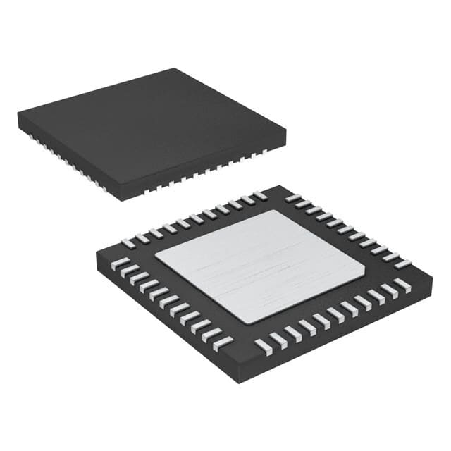
- Part No.:
- MAX6963ATH+
- Manufacturer:
- Analog Devices Inc./Maxim Integrated
- Category:
- Display Drivers
- Package:
- -
- Datasheet:
-
 MAX6963ATH+.pdf
- Description:
- IC DRIVER LED MATRIX 44-TQFN
- Quantity:
- Payment:

- Shipping:

Inventory:2,655
Please send an inquiry. Send us your inquiry, and we will respond immediately.
Product details
Overview
MAX6963ATH+ from Maxim Integrated is a compact 44-pin TQFN cathode-row LED display driver IC designed for 8 × 8 monocolor dot-matrix displays. It operates from 2.7V to 3.6V, delivers up to 40mA peak segment current per digit, supports two-step intensity control, and integrates open/short LED detection for reliability in industrial signage and message boards.
For engineers reviewing the MAX6963ATH+ datasheet, MAX6963ATH+ pinout, MAX6963ATH+ application, or MAX6963ATH+ equivalent, this page provides verified technical context, validated pin functions, confirmed monocolor display support with digit-level current calibration, and real-world selection guidance against comparable LED drivers.
Technical Context
The MAX6963ATH+ implements a high-speed 20MHz 4-wire serial interface (DIN/CLK/CS/RST) with tri-state DOUT for daisy-chaining. Its architecture uses frame-modulated 12-frame superframes for pixel-level intensity control and supports automatic plane switching from 63Hz to one frame every 63 seconds with interrupt capability via ADDOUT.
It features dual digit-by-digit analog/digital current calibration (RISET0/RISET1), local 3-wire address bus (ADDIN/ADDCLK/ADDOUT) for memory mapping across up to 256 drivers, and slew-rate-limited segment drivers to reduce EMI. The device is configured exclusively for monocolor 8 × 8 displays - not RGY or RGB - with fixed 1-bit-per-pixel intensity mode and no C-bit or PI-bit programmability.
Key Specifications
| Parameter | Value and Actual Design Meaning |
|---|---|
| Supply Voltage | 2.7V to 3.6V - enables direct operation from standard 3.3V logic rails without level shifting. |
| Peak Segment Current | 40mA (digit 0) or 20mA (digit 1) - selectable per digit via RISET0/RISET1 pins for batch calibration. |
| Interface Speed | 20MHz serial clock - supports high-throughput display updates for animation at up to 63 frames/sec. |
| Operating Temp | −40°C to +125°C - qualified for industrial and automotive under-hood signage applications. |
| Display Support | Monocolor 8 × 8 matrix only - no RGY or RGB functionality; fixed 1-bit-per-pixel intensity mode. |
| LED Fault Detection | Open- and short-circuit detection per LED - enables automated diagnostics without external circuitry. |
| Memory Planes | Four 16-byte planes - allows double-buffered display updates with background image building. |
Pinout & Package
MAX6963ATH+ is housed in a 44-pin TQFN package with exposed pad (EP), requiring GND connection for thermal and electrical performance. Pin count and layout match the MAX6960–MAX6963 family's standardized footprint.
| Pin/Terminal | Circuit Role | Design Meaning |
|---|---|---|
| GND (Pins 1,6,11,12,44) | Ground reference | Primary return path for all internal currents; EP must be soldered to PCB ground plane. |
| ROW1–ROW8 (Pins 2–5,7–10) | Cathode sink drivers | Eight constant-current sinks for LED cathodes; each supports up to 750mA total row current. |
| COL1–COL16 (Pins 19–21,23–27,29–33,35–37) | Anode source drivers | Sixteen constant-current sources for LED anodes; each delivers up to 48mA peak column current. |
| OSC (Pin 13) | Master clock input | Accepts 1MHz–8.5MHz CMOS clock; enables internal timing and dead-clock protection. |
| CS/DIN/CLK/RST (Pins 14–18) | 4-wire serial interface | Enables command/data loading, global write broadcast, and hardware reset with 50ms power-up hold. |
| RISET0/RISET1 (Pins 42–43) | Digit current programming | Set digit 0/1 segment current to 40mA (GND), 20mA (open), or adjustable (resistor to GND). |
| ADDIN/ADDCLK/ADDOUT (Pins 40–41,39) | Local address bus | Auto-allocates memory map addresses across daisy-chained drivers; ADDOUT doubles as plane-change interrupt. |
Key Features
| Feature | Design Value |
|---|---|
| Digit-level current calibration | Independent 20mA/40mA selection per digit via RISET0/RISET1 enables color matching across LED batches. |
| Four-plane display memory | Allows seamless animation by preloading next frame while current plane refreshes - no software timing dependency. |
| Open/short LED detection | Hardware-level fault reporting per LED eliminates need for external sense resistors or firmware polling. |
| Slew-rate-limited drivers | Reduces EMI emissions during segment switching - critical for EMC-compliant industrial signage designs. |
| Global command broadcast | Single write operation synchronizes brightness, plane selection, or shutdown across entire daisy-chained panel. |
Applications
| Industrial Message Boards | Gaming Machine Displays |
|---|---|
Use Scenario: Indoor alphanumeric signage in factory environments requiring high reliability and wide temperature operation. IC Role / Device Role / Timing Role: Primary cathode-row LED driver controlling two 8×8 red LED digits per IC; manages multiplex timing and intensity scaling. Use Value: −40°C to +125°C rating ensures uptime in unconditioned industrial spaces; open/short detection reduces maintenance downtime. |
Use Scenario: Dynamic score and status displays on slot machines and arcade cabinets with frequent power cycling. IC Role / Device Role / Timing Role: Monocolor 8×8 display controller with four memory planes enabling smooth transitions between game states. Use Value: Low-power shutdown with full data retention preserves display state across power loss; 20MHz interface supports rapid UI updates. |
| Audio/Video Equipment Front Panels | Transportation Control Interfaces |
Use Scenario: Status indicators and channel selectors on professional AV mixers and amplifiers. IC Role / Device Role / Timing Role: Constant-current LED driver with digit-level current trim for consistent brightness across front-panel LEDs. Use Value: Analog/digital calibration compensates for LED forward-voltage variation - critical for uniform visual appearance. |
Use Scenario: Passenger information displays in rail or bus systems where vibration and thermal stress are present. IC Role / Device Role / Timing Role: Robust LED driver with built-in fault detection and auto-plane switching for scheduled content rotation. Use Value: ADDOUT interrupt signals plane changes to host MCU - simplifies synchronization in distributed display networks. |
Equivalent & Alternatives
The following parts are listed as comparable options for similar monocolor LED display driver applications.
| Alternative Part | Technical Difference | Application Difference | Selection Advice |
|---|---|---|---|
| MAX6962ATH+ | Supports both 1-bit and 2-bit-per-pixel intensity modes; includes RGY configuration bit (C-bit = 0) but not enabled for MAX6963. | Can drive monocolor displays with four-level intensity (vs. MAX6963ATH+'s two-level only); suitable for higher-contrast UIs. | Select MAX6962ATH+ if 2-bit-per-pixel grayscale or future RGY compatibility is required; MAX6963ATH+ is optimized for cost-sensitive monocolor-only use. |
| TLC59284DBQR | 16-channel constant-current sink driver; no integrated 4-wire interface, requires external SPI controller; max 45mA/channel. | Requires additional MCU GPIOs and firmware for display sequencing; lacks built-in plane memory or fault detection. | Choose TLC59284DBQR only when board space permits discrete control logic and lower integration is acceptable. |
Compared with MAX6962ATH+, MAX6963ATH+ sacrifices 2-bit intensity and RGY support for tighter BOM control and simplified configuration; versus TLC59284DBQR, it delivers full display subsystem integration - eliminating external timing, memory, and diagnostics circuitry.
Availability
MAX6963ATH+ is available at Aetrix Electronics and suitable for industrial message boards, gaming machine displays, audio/video front panels, and transportation control interfaces requiring stable component supply across extended temperature ranges and long production lifecycles.
Supply support for MAX6963ATH+ includes scheduled delivery planning, volume procurement assistance, BOM continuity management, traceable sourcing, and lifecycle availability coordination for OEM customers, industrial embedded developers, connected-device designers, and electronics production programs.
Manufacturer
Maxim Integrated, now part of Analog Devices, designs precision analog and mixed-signal ICs for industrial, automotive, and communications applications.
The MAX6960–MAX6963 product line was engineered specifically for high-reliability, low-maintenance LED signage - delivering integrated current control, fault detection, and multi-driver synchronization in a single chip.
FAQ
What display types does the MAX6963ATH+ support?
The MAX6963ATH+ supports only monocolor 8 × 8 cathode-row LED matrices - such as red or orange/yellow displays - with fixed 1-bit-per-pixel intensity control. It does not support RGY or RGB configurations, nor does it enable the C-bit or PI-bit registers found in MAX6960/MAX6961/MAX6962. This limitation is hard-coded in the silicon and confirmed in the datasheet's Table 1 and "Selecting the Appropriate Driver" section.
How does the MAX6963ATH+ handle LED fault detection?
The MAX6963ATH+ performs real-time open- and short-circuit detection on every LED segment using internal sensing circuitry. When a fault occurs, it flags the condition in the fault register and can assert an interrupt via the ADDOUT pin. No external components or firmware polling are required - the feature is fully autonomous and documented in the "Fault Detection" section of the datasheet.
Can the MAX6963ATH+ drive RGB displays directly?
No, the MAX6963ATH+ cannot drive RGB displays directly. Its output voltage headroom and internal architecture are limited to LED forward voltages ≤2.5V - insufficient for blue LEDs (typically 3.5V–4.5V). However, the MAX6963ATH+ can serve as a graphics controller paired with external pass transistors for RGB anode-row configurations, retaining all intensity and memory features as described in Figure 17 of the datasheet.
What is the role of RISET0 and RISET1 on the MAX6963ATH+?
RISET0 and RISET1 on the MAX6963ATH+ set the peak segment current for digit 0 and digit 1 independently: grounding either pin selects 40mA, leaving it open selects 20mA, and connecting via resistor enables fine analog adjustment between 20mA and 40mA. This allows per-digit brightness calibration to compensate for LED batch variations - a key capability confirmed in the "Pin Description" and "Display Intensity Control" sections.
Does the MAX6963ATH+ require an external crystal or oscillator?
No, the MAX6963ATH+ does not require an external crystal. It accepts a 1MHz–8.5MHz CMOS-compatible clock signal on the OSC pin - which may come from an MCU, dedicated oscillator IC, or crystal oscillator circuit. The device includes dead-clock protection that disables outputs if OSC stops, as specified in the Absolute Maximum Ratings and Electrical Characteristics tables.
MAX6963ATH+ Specifications
- Product attributes
- Attribute value
- Manufacturer:
- Analog Devices Inc./Maxim Integrated
- Series:
- *
- Package/Case:
- -
- Packaging:
- Product Status:
- Obsolete
- Display Type:
- -
- Configuration:
- -
- Interface:
- -
- Digits or Characters:
- -
- Current - Supply:
- -
- Voltage - Supply:
- -
- Operating Temperature:
- -
- Grade:
- -
- Qualification:
- -
- Mounting Type:
- -
- Supplier Device Package:
- -
MAX6963ATH+ FAQ
1.How can I place an order for MAX6963ATH+ through Aetrix?
Please submit a Request for Quotation (RFQ) for MAX6963ATH+ on Aetrix. Our sales agent will provide a competitive quotation and guide you through the order confirmation once you accept the terms.
2.Are the price and stock information for MAX6963ATH+ reliable?
The price and inventory of MAX6963ATH+ are updated periodically and may fluctuate due to market conditions. Stock and pricing data are typically refreshed every 24 hours. Quotation validity for MAX6963ATH+ is usually 5 days.
3.What payment methods are accepted for MAX6963ATH+?
We accept Wire Transfer, PayPal, Credit Card, Western Union, MoneyGram, and Escrow for MAX6963ATH+ transactions.
Note: Certain payment methods may incur a processing fee.
4.How is shipping managed for MAX6963ATH+?
MAX6963ATH+ orders can be shipped via leading logistics carriers, including DHL, UPS, FedEx, TNT, or Registered Mail.
Once your MAX6963ATH+ order is processed, you will receive an email with the shipment details and tracking number.
Note: Tracking information may take up to 24 hours to appear. Express delivery typically takes 3–5 business days.
5.How can I obtain technical support or documentation for MAX6963ATH+?
For technical support, including MAX6963ATH+ datasheets, pinout diagrams, or application guidance, please contact our engineering support team. They can provide detailed documentation and assistance for your MAX6963ATH+ requirements.
6.How does Aetrix verify that MAX6963ATH+ is sourced from the original manufacturer or authorized distributors?
All MAX6963ATH+ products on Aetrix are procured from qualified distributors and authorized channels. Our dedicated quality assurance team conducts strict verification, including traceability checks and, if necessary, third-party testing. This ensures that MAX6963ATH+ meets industry standards.
7.What is the process for return or replacement of MAX6963ATH+?
All MAX6963ATH+ units undergo pre-shipment inspection (PSI). If there is an issue with MAX6963ATH+, returns or replacements are accepted under the following conditions:
1.Quantity discrepancies, incorrect items, or visible external defects (such as breakage or corrosion), acknowledged by Aetrix.
2.The issue is reported within 90 days of delivery.
3.The MAX6963ATH+ part is unused and in its original packaging.
Return procedure for MAX6963ATH+:
1.Submit a request within 90 days.
2.Obtain a Return Material Authorization (RMA) from Aetrix.
MAX6963ATH+ Tags

-
PCA8561AHN/AY
NXP Semiconductors

-
SN74LS47N
Texas Instruments

-
PCF85176T/1Y
NXP Semiconductors
-
PCF85176H/1,518
NXP Semiconductors

-
BU9796AMUV-E2
Rohm Semiconductor
-
PCA85176H/Q900/1,5
NXP Semiconductors
-
PCF8537AH/1,518
NXP Semiconductors

-
LM3914VX/NOPB
Texas Instruments

-
PCF85134HL/1,118
NXP Semiconductors

-
AS1115-BSST
ams-OSRAM USA INC.
-
PCA8534AH/Q900/1,5
NXP Semiconductors
-
LM3914V/NOPB
Texas Instruments
Tech Hub

A practical engineering guide to 3.3V and 5V logic compatibility, input thresholds, resistor dividers, translator ICs, MOSFET level shifting, I2C pull-ups, timing limits and power-sequencing risks.

The 74HC595 uses push-pull logic outputs, while the TPIC6B595 uses 50 V open-drain DMOS sinks for higher-power loads. This guide compares timing, current limits, 3.3 V interfacing, load wiring, thermal…

The 74HC595 converts serial data into eight stable parallel outputs. This guide covers pin functions, shift and storage timing, OE and MR behavior, drive-current limits, cascading, voltage compatibilit…

A technical comparison of level-sensitive latches and edge-triggered flip-flops, covering timing windows, setup and hold limits, master–slave operation, time borrowing, race-through, HDL inference and…

A D latch stores one bit while Enable controls when data can pass. This reference covers gate-level operation, truth tables, transparency, setup and hold timing, LE versus OE, common ICs and practical …

An SR latch stores one bit through cross-coupled feedback. This engineering reference covers NOR and NAND implementations, truth tables, forbidden-state recovery, gated operation, switch debouncing, fa…

Latch circuits retain one bit through feedback. This technical reference covers SR and D latches, truth tables, transparency, timing limits, latch-versus-flip-flop behavior, applications and common log…

An engineering guide to LED driver operation, constant-current and constant-voltage outputs, linear and switching topologies, dimming, IC selection, calculations, replacement compatibility, and fault c…

Operational amplifier guide covering op amp basics, feedback, ideal vs real op amps, common configurations, buffer circuits, offset, bias current, gain-bandwidth, slew rate, rail-to-rail limits and sel…

Jumper cables guide covering safe connection order, red and black clamp placement, final ground connection, cable gauge, length, clamp quality, copper vs CCA cables, jump starter comparison and battery…


