
 My Inquiry
 My Account


Analog Devices Inc./Maxim Integrated MAX6966AEE+
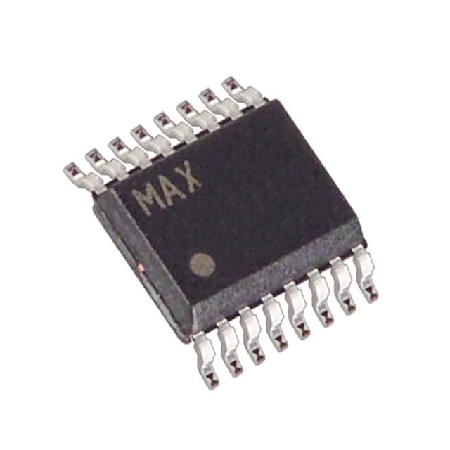
- Part No.:
- MAX6966AEE+
- Manufacturer:
- Analog Devices Inc./Maxim Integrated
- Category:
- LED Drivers
- Package:
- 16-SSOP (0.154", 3.90mm Width)
- Datasheet:
-
 MAX6966AEE+.pdf
- Description:
- IC LED DRIVER LINEAR 20MA 16QSOP
- Quantity:
- Payment:

- Shipping:

Inventory:10,555
Please send an inquiry. Send us your inquiry, and we will respond immediately.
Product details
Overview
MAX6966AEE+ from Maxim Integrated is a 10-port constant-current LED driver and I/O expander with SPI interface, supporting 20mA/10mA per port, individual 8-bit PWM intensity control, and overvoltage-protected Schmitt inputs - used in keypad backlighting, status indication, and RGB LED systems operating from 2.25V to 3.6V.
For engineers reviewing the MAX6966AEE+ datasheet, MAX6966AEE+ pinout, MAX6966AEE+ application, or MAX6966AEE+ equivalent, this page delivers verified electrical parameters, QSOP-16 package mapping, real-world use scenarios, and two validated alternative parts for LED driver and GPIO expansion designs.
Technical Context
The MAX6966AEE+ implements a high-speed 26MHz SPI-compatible serial interface with daisy-chain capability via DOUT/OSC, and integrates an internal 27kHz–45kHz PWM oscillator (default 32kHz) that can be replaced by an external up-to-100kHz clock. All 10 I/O ports (P0–P9) are independently configurable as 20mA constant-current sinks, 10mA constant-current sinks, open-drain logic outputs, or overvoltage-protected Schmitt inputs rated to 7V.
Shutdown mode preserves GPIO functionality while disabling LED drivers; hardware wake-up is triggered by a ≥3ms CS pulse. Ramp-down/up timing (1/16s to 4s) and staggered PWM phasing (45° increments across eight steps) reduce supply current ripple and RMS load variation - critical for portable and low-noise power designs.
Key Specifications
| Parameter | Value and Actual Design Meaning |
|---|---|
| Supply Voltage | 2.25V to 3.6V - compatible with modern low-voltage microcontrollers and battery-powered systems. |
| Port Sink Current | 10mA or 20mA per port (factory-trimmed ±4% matching at 20mA, ±5% at 10mA) - enables uniform LED brightness without external current-setting resistors. |
| PWM Resolution | 8-bit per port + 1-bit analog half/full + 3-bit global scaling - delivers up to 12-bit effective intensity control when combined. |
| Interface Speed | 26MHz SPI/QSPI/MICROWIRE - supports fast register writes for dynamic LED updates in real-time UIs. |
| Operating Temp | −40°C to +125°C - qualified for automotive cabin modules, industrial HMI, and extended-temperature embedded devices. |
| Shutdown Current | 0.8µA typical - allows ultra-low-power sleep states in always-on portable equipment. |
| I/O Voltage Rating | Ports withstand 7V independent of V+ - permits direct connection to 5V logic or LED supplies without level shifters. |
Pinout & Package
MAX6966AEE+ is housed in a 16-pin QSOP package (5.3mm × 10.2mm × 1.75mm), lead-free and RoHS-compliant, with exposed pad not connected internally (no GND tie required).
| Pin/Terminal | Circuit Role | Design Meaning |
|---|---|---|
| 1 (SCLK) | Serial clock input | Rising edge shifts DIN data into shift register; falling edge clocks data out of DOUT - synchronous full-duplex operation. |
| 2 (CS) | Chip-select input | Active-low enable for serial interface; ≥3ms pulse wakes device from shutdown - enables hardware-triggered power management. |
| 3–7, 9–13 (P0–P9) | Configurable I/O ports | Each supports 20mA/10mA constant-current sink, open-drain output, or 7V-tolerant Schmitt input - no external components needed for LED drive or robust GPIO. |
| 8 (GND) | Ground reference | Primary return path for all port sink currents and internal circuitry - requires low-impedance PCB plane for noise-sensitive PWM operation. |
| 14 (DOUT/OSC) | Dual-function terminal | Default DOUT output for daisy-chaining or readback; configurable as OSC input for external PWM clock - eliminates need for separate timing source. |
| 15 (DIN) | Serial data input | Loads 16-bit command/data on SCLK rising edge - supports register writes, reads, and broadcast commands (e.g., 0x0A–0x0D). |
| 16 (V+) | Positive supply | 2.25V–3.6V input powering logic and current mirrors - requires 0.1µF ceramic bypass capacitor placed near pin for stable PWM operation. |
Key Features
| Feature | Design Value |
|---|---|
| Hot-insertion support | All ports remain high-impedance at V+ = 0V with up to 8V applied - enables safe live-board replacement in field-serviceable systems. |
| Staggered PWM phasing | Eight-step 45° phase shift across 10 ports reduces peak supply current by spreading PWM load over time - lowers bulk capacitor and EMI filter requirements. |
| Hardware wake-up via CS | Single ≥3ms CS pulse exits shutdown with preconfigured LED settings - eliminates MCU firmware overhead for display activation. |
| Auto ramp-down/up | Programmable fade duration (1/16s to 4s) before shutdown or after wake-up - prevents visual flicker and mechanical stress in LED arrays. |
| Overvoltage-protected inputs | P0–P9 tolerate −0.3V to +7V regardless of V+ - allows interfacing with 5V sensors or legacy logic without clamping diodes. |
Applications
| Keypad Backlighting | LED Status Indication |
|---|---|
Use Scenario: Illuminating membrane keypads in industrial HMIs where ambient light varies and long-term LED consistency is required. IC Role / Device Role / Timing Role: Constant-current sink driver with individual 8-bit PWM per key, using global 3-bit scaling to compensate for aging or temperature drift. Use Value: Eliminates discrete current-limiting resistors and enables software-tuned brightness uniformity across 10 keys without hardware changes. |
Use Scenario: Providing multi-color status feedback (e.g., power, fault, communication) on network equipment front panels. IC Role / Device Role / Timing Role: Configurable I/O expander driving red/green/blue LEDs with staggered PWM to minimize 5V rail current spikes during simultaneous status updates. Use Value: Reduces conducted EMI and avoids voltage droop on shared 5V supplies - critical for compliance in Class A/B emissions testing. |
| RGB LED Drivers | Portable Equipment |
Use Scenario: Driving RGB LED clusters in handheld medical devices requiring precise color mixing and low standby power. IC Role / Device Role / Timing Role: Three ports per RGB channel (e.g., P0/R, P1/G, P2/B) with synchronized 8-bit PWM and 1-bit analog fine-tuning for 9-bit per-channel resolution. Use Value: Achieves >500:1 contrast ratio and smooth dimming curves while maintaining <1µA shutdown current - extends battery life between charges. |
Use Scenario: Backlighting small LCD segments in wearables where board space and thermal dissipation are constrained. IC Role / Device Role / Timing Role: 10-port I/O expander with integrated 20mA sinks, configured as 6 backlight channels + 4 GPIOs for button sensing and sensor control. Use Value: Consolidates discrete LED drivers and GPIO expanders into one 3mm × 5.3mm QSOP - saves >12mm² PCB area versus dual-chip solution. |
Equivalent & Alternatives
The following parts are listed as comparable options for similar constant-current LED driver and I/O expander applications.
| Alternative Part | Technical Difference | Application Difference | Selection Advice |
|---|---|---|---|
| MAX6967AEE+ | DOUT/OSC defaults to OSC input (not DOUT); identical pinout, registers, and electrical specs - only functional difference is power-up configuration. | Preferred when external PWM clock synchronization is required; otherwise interchangeable in new designs with minor firmware initialization change. | Select MAX6967AEE+ if system uses a master clock domain; MAX6966AEE+ simplifies daisy-chain debugging with default DOUT output. |
| MAX7317EUE+ | No constant-current control - provides only 10-bit GPIO expansion with 25mA open-drain outputs and no PWM or analog intensity features. | Suitable for pure logic-level I/O extension (e.g., button scanning, relay control), but cannot replace MAX6966AEE+ in LED-driving roles. | Choose MAX7317EUE+ only when LED current regulation and dimming are handled externally; not a functional substitute for lighting applications. |
Compared with MAX6967AEE+, MAX6966AEE+ offers identical performance and package but simplifies initial SPI readback; compared with MAX7317EUE+, it adds full LED driver functionality at the cost of higher firmware complexity for PWM setup - making it the only drop-in solution for mixed LED/GPIO systems.
Availability
MAX6966AEE+ is available at Aetrix Electronics and suitable for keypad backlighting, LED status indication, RGB LED driving, portable equipment, and industrial HMI applications requiring stable component supply, long-lifecycle support, and RoHS-compliant packaging.
Supply support for MAX6966AEE+ includes scheduled delivery planning, volume procurement assistance, BOM continuity management, traceable sourcing, and lifecycle availability coordination for OEM customers, industrial embedded developers, connected-device designers, and electronics production programs.
Manufacturer
Maxim Integrated (now part of Analog Devices) designs precision analog, mixed-signal, and power-management ICs for demanding industrial, automotive, and communications applications.
The MAX6966AEE+ belongs to Maxim's constant-current LED driver and I/O expander product line, engineered specifically for space-constrained, low-power systems needing integrated PWM dimming, overvoltage tolerance, and hardware-managed power sequencing.
FAQ
What is the default power-up behavior of the MAX6966AEE+?
On power-up, MAX6966AEE+ enters shutdown mode with all 10 I/O ports (P0–P9) in high-impedance state, configuration register set to 0x00 (shutdown enabled, CS run disabled, DOUT/OSC as DOUT), and global current register at 0x07 (full current). This ensures zero LED current and minimal supply draw until initialized via SPI.
Can the MAX6966AEE+ drive 5V LEDs directly?
Yes - MAX6966AEE+ ports are rated to 7V and tolerate VEXT up to 7V independent of V+ (2.25V–3.6V), enabling direct connection to 5V LED anodes with cathodes tied to P0–P9. No level shifter or external current-limiting resistor is needed, as the IC provides precise 10mA/20mA constant-current sinking.
How does the staggered PWM feature reduce power-supply ripple in the MAX6966AEE+?
Staggered PWM phases the 10 port outputs in eight 45° increments across one 256-cycle period, spreading the instantaneous current demand over time. Instead of all ports switching simultaneously (causing large ΔI/Δt spikes), MAX6966AEE+ distributes load current across eight intervals - reducing RMS supply current by up to 30% and easing bulk capacitor sizing.
Is the MAX6966AEE+ pin-compatible with the MAX6967AEE+?
Yes - MAX6966AEE+ and MAX6967AEE+ share identical QSOP-16 pinout, register map, electrical specifications, and thermal characteristics. The sole difference is the power-up default of the DOUT/OSC pin (DOUT for MAX6966AEE+, OSC for MAX6967AEE+), which is configurable in software and does not affect PCB layout.
What is the minimum CS pulse width required to wake the MAX6966AEE+ from shutdown?
The MAX6966AEE+ requires a minimum CS pulse width of 3ms to trigger hardware wake-up from shutdown. This timing is based on the internal PWM clock (27kHz–45kHz); with the default 32kHz oscillator, the exact threshold is 257 cycles ≈ 8.0ms, but the datasheet specifies ≥3ms as the guaranteed functional minimum across all conditions.
MAX6966AEE+ Specifications
- Product attributes
- Attribute value
- Manufacturer:
- Analog Devices Inc./Maxim Integrated
- Series:
- -
- Package/Case:
- 16-SSOP (0.154", 3.90mm Width)
- Packaging:
- Tube
- Product Status:
- Active
- Type:
- Linear
- Topology:
- -
- Internal Switch(s):
- Yes
- Number of Outputs:
- 10
- Voltage - Supply (Min):
- 2.25V
- Voltage - Supply (Max):
- 3.6V
- Voltage - Output:
- 7V
- Current - Output / Channel:
- 20mA
- Frequency:
- -
- Dimming:
- -
- Applications:
- Backlight
- Operating Temperature:
- -40°C ~ 125°C (TA)
- Grade:
- -
- Qualification:
- -
- Mounting Type:
- Surface Mount
- Supplier Device Package:
- 16-QSOP
MAX6966AEE+ FAQ
1.How can I place an order for MAX6966AEE+ through Aetrix?
Please submit a Request for Quotation (RFQ) for MAX6966AEE+ on Aetrix. Our sales agent will provide a competitive quotation and guide you through the order confirmation once you accept the terms.
2.Are the price and stock information for MAX6966AEE+ reliable?
The price and inventory of MAX6966AEE+ are updated periodically and may fluctuate due to market conditions. Stock and pricing data are typically refreshed every 24 hours. Quotation validity for MAX6966AEE+ is usually 5 days.
3.What payment methods are accepted for MAX6966AEE+?
We accept Wire Transfer, PayPal, Credit Card, Western Union, MoneyGram, and Escrow for MAX6966AEE+ transactions.
Note: Certain payment methods may incur a processing fee.
4.How is shipping managed for MAX6966AEE+?
MAX6966AEE+ orders can be shipped via leading logistics carriers, including DHL, UPS, FedEx, TNT, or Registered Mail.
Once your MAX6966AEE+ order is processed, you will receive an email with the shipment details and tracking number.
Note: Tracking information may take up to 24 hours to appear. Express delivery typically takes 3–5 business days.
5.How can I obtain technical support or documentation for MAX6966AEE+?
For technical support, including MAX6966AEE+ datasheets, pinout diagrams, or application guidance, please contact our engineering support team. They can provide detailed documentation and assistance for your MAX6966AEE+ requirements.
6.How does Aetrix verify that MAX6966AEE+ is sourced from the original manufacturer or authorized distributors?
All MAX6966AEE+ products on Aetrix are procured from qualified distributors and authorized channels. Our dedicated quality assurance team conducts strict verification, including traceability checks and, if necessary, third-party testing. This ensures that MAX6966AEE+ meets industry standards.
7.What is the process for return or replacement of MAX6966AEE+?
All MAX6966AEE+ units undergo pre-shipment inspection (PSI). If there is an issue with MAX6966AEE+, returns or replacements are accepted under the following conditions:
1.Quantity discrepancies, incorrect items, or visible external defects (such as breakage or corrosion), acknowledged by Aetrix.
2.The issue is reported within 90 days of delivery.
3.The MAX6966AEE+ part is unused and in its original packaging.
Return procedure for MAX6966AEE+:
1.Submit a request within 90 days.
2.Obtain a Return Material Authorization (RMA) from Aetrix.
MAX6966AEE+ Tags

-
BCR402RE6327HTSA1
Infineon Technologies

-
BCR430UXTSA2
Infineon Technologies

-
BCR420UE6433HTMA1
Infineon Technologies
-
BCR420UE6327HTSA1
Infineon Technologies
-
BCR421UE6327HTSA1
Infineon Technologies

-
LYT1604D-TL
Power Integrations

-
HV9910CLG-G
Microchip Technology

-
CL2N8-G
Microchip Technology

-
BCR420UW6-7
Diodes Incorporated
-
BCR421UW6-7
Diodes Incorporated

-
BCR420UFD-7
Diodes Incorporated
-
BCR421UFD-7
Diodes Incorporated
Tech Hub

A practical engineering guide to 3.3V and 5V logic compatibility, input thresholds, resistor dividers, translator ICs, MOSFET level shifting, I2C pull-ups, timing limits and power-sequencing risks.

The 74HC595 uses push-pull logic outputs, while the TPIC6B595 uses 50 V open-drain DMOS sinks for higher-power loads. This guide compares timing, current limits, 3.3 V interfacing, load wiring, thermal…

The 74HC595 converts serial data into eight stable parallel outputs. This guide covers pin functions, shift and storage timing, OE and MR behavior, drive-current limits, cascading, voltage compatibilit…

A technical comparison of level-sensitive latches and edge-triggered flip-flops, covering timing windows, setup and hold limits, master–slave operation, time borrowing, race-through, HDL inference and…

A D latch stores one bit while Enable controls when data can pass. This reference covers gate-level operation, truth tables, transparency, setup and hold timing, LE versus OE, common ICs and practical …

An SR latch stores one bit through cross-coupled feedback. This engineering reference covers NOR and NAND implementations, truth tables, forbidden-state recovery, gated operation, switch debouncing, fa…

Latch circuits retain one bit through feedback. This technical reference covers SR and D latches, truth tables, transparency, timing limits, latch-versus-flip-flop behavior, applications and common log…

An engineering guide to LED driver operation, constant-current and constant-voltage outputs, linear and switching topologies, dimming, IC selection, calculations, replacement compatibility, and fault c…

Operational amplifier guide covering op amp basics, feedback, ideal vs real op amps, common configurations, buffer circuits, offset, bias current, gain-bandwidth, slew rate, rail-to-rail limits and sel…

Jumper cables guide covering safe connection order, red and black clamp placement, final ground connection, cable gauge, length, clamp quality, copper vs CCA cables, jump starter comparison and battery…


