
 My Inquiry
 My Account


Analog Devices Inc./Maxim Integrated MAX7219CWG-T
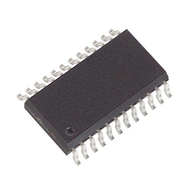
- Part No.:
- MAX7219CWG-T
- Manufacturer:
- Analog Devices Inc./Maxim Integrated
- Category:
- Display Drivers
- Package:
- 24-SOIC (0.295", 7.50mm Width)
- Datasheet:
-
 MAX7219CWG-T.pdf
- Description:
- IC DRVR 7 SEGMNT 8 DIGIT 24SOIC
- Quantity:
- Payment:

- Shipping:

Inventory:3,194
Please send an inquiry. Send us your inquiry, and we will respond immediately.
Product details
Overview
MAX7219CWG-T from Maxim Integrated is a serially interfaced, common-cathode 8-digit LED display driver IC with integrated BCD decoder, 8×8 static RAM, multiplex scan circuitry, and segment/digit drivers. It operates from 4.0V to 5.5V, supports 10MHz SPI-compatible serial interface, delivers up to −40mA segment source current and 320mA digit sink current, and enables individual digit update without full display rewrite - used in industrial panel meters and embedded LED signage.
For engineers reviewing the MAX7219CWG-T datasheet, MAX7219CWG-T pinout, MAX7219CWG-T application, or MAX7219CWG-T equivalent, key selection criteria include its 24-pin wide SO package, decode/no-decode per-digit flexibility, 150µA shutdown current, analog + digital brightness control, and compatibility with microprocessor-based LED display systems requiring stable segment current regulation via external RSET.
Technical Context
The MAX7219CWG-T implements an 8-digit multiplexed display architecture with internal 8×8 dual-port SRAM for digit storage, a BCD code-B decoder (configurable per digit), and a pulse-width modulator for 16-step digital intensity control (31/32 to 1/32 of peak current). Its segment drivers source current while digit drivers sink current, with all digit outputs pulled to V+ when off.
It uses a 16-bit serial frame format (D15–D0) with D8–D11 as register address bits and D0–D7 as data; latching occurs on LOAD rising edge. The device features interdigit blanking, scan-limit register (1–8 digits), shutdown mode (halts oscillator, retains RAM), and display-test mode (all LEDs forced on).
Key Specifications
| Parameter | Value and Actual Design Meaning |
|---|---|
| Supply Voltage | 4.0V to 5.5V - compatible with standard +5V logic rails and tolerant of ±10% variation |
| Segment Source Current | −40mA max at VOUT = V+ − 1V - sets peak LED brightness; adjusted via external RSET resistor |
| Digit Sink Current | 320mA max per digit - supports high-brightness common-cathode displays with up to 8 digits |
| Serial Interface Speed | 10MHz max CLK rate - enables fast display updates and daisy-chained configurations |
| Shutdown Current | 150µA - preserves RAM contents while minimizing power in standby or alarm-flash modes |
| Display Scan Rate | 500–1300Hz (8-digit typical 800Hz) - determines flicker-free visibility and effective brightness |
| Operating Temp Range | 0°C to +70°C - suitable for commercial and industrial indoor applications |
Pinout & Package
MAX7219CWG-T is housed in a 24-pin wide SOIC (SO) package (package code W24+1), RoHS-compliant, with 0.300" body width and standard gull-wing lead form.
| Pin/Terminal | Circuit Role | Design Meaning |
|---|---|---|
| DIN | Serial data input | Accepts 16-bit command frames on CLK rising edges; MSB-first, D15 first |
| LOAD (CS) | Latch control / chip select | Rising edge latches last 16 bits into digit/control registers; shared function across MAX7219/MAX7221 variants |
| CLK | Serial clock input | 10MHz max; rising edge shifts data in, falling edge clocks data out on DOUT |
| DOUT | Serial data output | Non-inverting CMOS output; enables daisy-chaining with 16.5-cycle propagation delay |
| ISET | Current reference input | Connects to V+ via RSET; sets segment current ≈ 100 × IISET (e.g., 9.53kΩ → ~40mA) |
| V+ | Positive supply | +5V nominal; powers internal logic, drivers, and RAM; requires local 10µF + 0.1µF bypass |
| GND (pins 4, 9) | Ground reference | Both pins must be connected to minimize noise and ensure proper digit driver operation |
| DIG 0–DIG 7 | Digit sink outputs | Common-cathode digit lines; pulled to V+ when off (MAX7219); high-impedance in MAX7221 |
| SEG A–SEG G, DP | Segment source outputs | Drive LED anodes; active-high logic in no-decode mode; DP controlled by bit D7 |
Key Features
| Feature | Design Value |
|---|---|
| Per-digit decode/no-decode selection | Enables mixed-mode displays (e.g., numeric digits + alphanumeric symbols) without external logic |
| 16-step digital intensity control | Allows precise brightness tuning via software (intensity register) independent of RSET setting |
| Individual digit addressing & update | Reduces µP overhead: write only changed digits instead of full 8-digit refresh every cycle |
| Display-test mode | Hardware-level diagnostic: forces all segments on without altering register contents or requiring firmware intervention |
| Scan-limit programmability (1–8 digits) | Adjusts multiplex duty cycle dynamically; critical for thermal management when driving <4 digits |
Applications
| Industrial Panel Meters | Embedded LED Signage |
|---|---|
Use Scenario: Real-time voltage/current/power readouts in DIN-rail mounted instrumentation cabinets. IC Role / Device Role / Timing Role: Display controller managing 4–8 digit numeric readouts with decimal point positioning and leading-zero suppression handled externally. Use Value: Reduces µP GPIO count and firmware complexity by integrating RAM, decoding, and multiplex timing - enabling compact, low-cost meter designs. |
Use Scenario: Status indicators and parameter displays in HVAC controllers, PLC HMI modules, and building automation panels. IC Role / Device Role / Timing Role: Serial interface bridge between MCU and multi-digit LED array; handles persistence-of-vision scanning autonomously. Use Value: Eliminates need for dedicated display timer peripherals or software-driven multiplexing, freeing MCU resources for control algorithms. |
| Test Equipment Front Panels | Point-of-Sale Terminal Displays |
Use Scenario: Digital multimeters and oscilloscope readouts requiring high legibility, stable brightness, and rapid value updates. IC Role / Device Role / Timing Role: High-current segment driver with analog + digital brightness control to maintain consistent luminance across temperature and supply variance. Use Value: Ensures calibrated display output under varying ambient conditions - critical for measurement accuracy perception and user confidence. |
Use Scenario: Price, item count, and transaction status displays in retail terminals operating 24/7 in varied lighting environments. IC Role / Device Role / Timing Role: Low-power display manager supporting shutdown mode for energy savings during idle periods while retaining display state. Use Value: Extends system uptime and reduces thermal load in enclosed enclosures - improves long-term reliability and fanless design feasibility. |
Equivalent & Alternatives
The following parts are listed as comparable options for similar LED display driver applications.
| Alternative Part | Technical Difference | Application Difference | Selection Advice |
|---|---|---|---|
| MAX7221CWG-T | Slew-rate limited segment drivers (reduces EMI); SPI/QSPI/MICROWIRE fully compliant; digit drivers high-impedance when off | Better suited for noise-sensitive environments (e.g., medical, test equipment); requires CS-driven protocol instead of LOAD | Select MAX7221CWG-T when EMI compliance or strict SPI interoperability is required; not pin/software identical due to CS vs LOAD timing behavior |
| TM1650 | 4-digit, I²C interface, integrated key-scan; lower segment current (15mA), no external RSET; no decode/no-decode per-digit flexibility | Targeted at cost-sensitive consumer UIs with buttons; lacks 8-digit capability and programmable scan limit | Choose TM1650 only for simple 4-digit + keypad applications where I²C simplifies routing and µP resource constraints dominate |
Compared with MAX7221CWG-T and TM1650, the MAX7219CWG-T offers optimal balance of 8-digit flexibility, per-digit decode control, and proven robustness in industrial LED interfaces - while avoiding the EMI mitigation overhead of MAX7221 and the functional limitations of TM1650.
Availability
MAX7219CWG-T is available at Aetrix Electronics and suitable for industrial panel meters, embedded LED signage, and test equipment front panels requiring stable component supply, long-lifecycle support, and guaranteed traceable sourcing.
Supply support for MAX7219CWG-T includes scheduled delivery planning, volume procurement assistance, BOM continuity management, traceable sourcing, and lifecycle availability coordination for OEM customers, industrial embedded developers, connected-device designers, and electronics production programs.
Manufacturer
Maxim Integrated (now part of Analog Devices) is a semiconductor company specializing in precision analog, mixed-signal, and power management ICs for industrial, communications, and computing applications.
The MAX7219 product line was designed specifically for microprocessor-controlled LED display systems - delivering integrated memory, decoding, and high-current drive in a single serial-interface package to replace discrete driver + logic solutions.
FAQ
What is the maximum segment current supported by the MAX7219CWG-T?
The MAX7219CWG-T supports a maximum segment source current of −40mA at VOUT = V+ − 1V and TA = +25°C. This value is set by the external RSET resistor (e.g., 9.53kΩ yields ~40mA). Derating applies for fewer than 4 displayed digits per Table 9; for example, 3-digit operation limits segment current to 30mA to avoid excessive digit-driver power dissipation.
Does the MAX7219CWG-T support SPI communication?
The MAX7219CWG-T supports a 4-wire serial interface compatible with SPI physical layer (DIN, DOUT, CLK, LOAD), but it is not fully SPI protocol-compliant - it uses LOAD (not CS) for frame synchronization and does not support native SPI modes or bidirectional half-duplex operation. For strict SPI compliance, the pin-compatible MAX7221CWG-T is recommended.
How does the MAX7219CWG-T handle power-up initialization?
On power-up, the MAX7219CWG-T enters shutdown mode, blanks the display, resets all control registers, and defaults to scanning only digit 0 with minimum intensity and no decode enabled. The host µP must initialize the shutdown, decode, intensity, and scan-limit registers before normal display operation - failure to do so results in no visible output or incorrect digit rendering.
Can the MAX7219CWG-T drive common-anode LED displays?
No, the MAX7219CWG-T is designed exclusively for common-cathode LED displays: SEG pins source current to LED anodes, and DIG pins sink current from LED cathodes. Driving common-anode displays would require external level-shifting or inverting circuitry and is not supported by the internal architecture or datasheet specifications.
What is the purpose of the two GND pins on the MAX7219CWG-T?
The MAX7219CWG-T has two dedicated GND pins (pins 4 and 9) to provide separate return paths for digital logic and high-current digit driver circuits - reducing ground bounce, improving noise immunity, and ensuring stable operation during high-speed multiplexing. Both pins must be connected to the system ground plane with low-inductance traces; omitting either degrades display uniformity and may cause erratic behavior.
MAX7219CWG-T Specifications
- Product attributes
- Attribute value
- Manufacturer:
- Analog Devices Inc./Maxim Integrated
- Series:
- -
- Package/Case:
- 24-SOIC (0.295", 7.50mm Width)
- Packaging:
- Tape & Reel (TR)
- Product Status:
- Obsolete
- Display Type:
- LED
- Configuration:
- 7 Segment + DP
- Interface:
- 4-Wire Serial
- Digits or Characters:
- 8 Digits
- Current - Supply:
- 330 mA
- Voltage - Supply:
- 4V ~ 5.5V
- Operating Temperature:
- 0°C ~ 70°C
- Grade:
- -
- Qualification:
- -
- Mounting Type:
- Surface Mount
- Supplier Device Package:
- 24-SOIC
MAX7219CWG-T FAQ
1.How can I place an order for MAX7219CWG-T through Aetrix?
Please submit a Request for Quotation (RFQ) for MAX7219CWG-T on Aetrix. Our sales agent will provide a competitive quotation and guide you through the order confirmation once you accept the terms.
2.Are the price and stock information for MAX7219CWG-T reliable?
The price and inventory of MAX7219CWG-T are updated periodically and may fluctuate due to market conditions. Stock and pricing data are typically refreshed every 24 hours. Quotation validity for MAX7219CWG-T is usually 5 days.
3.What payment methods are accepted for MAX7219CWG-T?
We accept Wire Transfer, PayPal, Credit Card, Western Union, MoneyGram, and Escrow for MAX7219CWG-T transactions.
Note: Certain payment methods may incur a processing fee.
4.How is shipping managed for MAX7219CWG-T?
MAX7219CWG-T orders can be shipped via leading logistics carriers, including DHL, UPS, FedEx, TNT, or Registered Mail.
Once your MAX7219CWG-T order is processed, you will receive an email with the shipment details and tracking number.
Note: Tracking information may take up to 24 hours to appear. Express delivery typically takes 3–5 business days.
5.How can I obtain technical support or documentation for MAX7219CWG-T?
For technical support, including MAX7219CWG-T datasheets, pinout diagrams, or application guidance, please contact our engineering support team. They can provide detailed documentation and assistance for your MAX7219CWG-T requirements.
6.How does Aetrix verify that MAX7219CWG-T is sourced from the original manufacturer or authorized distributors?
All MAX7219CWG-T products on Aetrix are procured from qualified distributors and authorized channels. Our dedicated quality assurance team conducts strict verification, including traceability checks and, if necessary, third-party testing. This ensures that MAX7219CWG-T meets industry standards.
7.What is the process for return or replacement of MAX7219CWG-T?
All MAX7219CWG-T units undergo pre-shipment inspection (PSI). If there is an issue with MAX7219CWG-T, returns or replacements are accepted under the following conditions:
1.Quantity discrepancies, incorrect items, or visible external defects (such as breakage or corrosion), acknowledged by Aetrix.
2.The issue is reported within 90 days of delivery.
3.The MAX7219CWG-T part is unused and in its original packaging.
Return procedure for MAX7219CWG-T:
1.Submit a request within 90 days.
2.Obtain a Return Material Authorization (RMA) from Aetrix.
MAX7219CWG-T Tags

-
PCA8561AHN/AY
NXP Semiconductors

-
SN74LS47N
Texas Instruments

-
PCF85176T/1Y
NXP Semiconductors
-
PCF85176H/1,518
NXP Semiconductors

-
BU9796AMUV-E2
Rohm Semiconductor
-
PCA85176H/Q900/1,5
NXP Semiconductors
-
PCF8537AH/1,518
NXP Semiconductors

-
LM3914VX/NOPB
Texas Instruments

-
PCF85134HL/1,118
NXP Semiconductors

-
AS1115-BSST
ams-OSRAM USA INC.
-
PCA8534AH/Q900/1,5
NXP Semiconductors
-
LM3914V/NOPB
Texas Instruments
Tech Hub

A practical engineering guide to 3.3V and 5V logic compatibility, input thresholds, resistor dividers, translator ICs, MOSFET level shifting, I2C pull-ups, timing limits and power-sequencing risks.

The 74HC595 uses push-pull logic outputs, while the TPIC6B595 uses 50 V open-drain DMOS sinks for higher-power loads. This guide compares timing, current limits, 3.3 V interfacing, load wiring, thermal…

The 74HC595 converts serial data into eight stable parallel outputs. This guide covers pin functions, shift and storage timing, OE and MR behavior, drive-current limits, cascading, voltage compatibilit…

A technical comparison of level-sensitive latches and edge-triggered flip-flops, covering timing windows, setup and hold limits, master–slave operation, time borrowing, race-through, HDL inference and…

A D latch stores one bit while Enable controls when data can pass. This reference covers gate-level operation, truth tables, transparency, setup and hold timing, LE versus OE, common ICs and practical …

An SR latch stores one bit through cross-coupled feedback. This engineering reference covers NOR and NAND implementations, truth tables, forbidden-state recovery, gated operation, switch debouncing, fa…

Latch circuits retain one bit through feedback. This technical reference covers SR and D latches, truth tables, transparency, timing limits, latch-versus-flip-flop behavior, applications and common log…

An engineering guide to LED driver operation, constant-current and constant-voltage outputs, linear and switching topologies, dimming, IC selection, calculations, replacement compatibility, and fault c…

Operational amplifier guide covering op amp basics, feedback, ideal vs real op amps, common configurations, buffer circuits, offset, bias current, gain-bandwidth, slew rate, rail-to-rail limits and sel…

Jumper cables guide covering safe connection order, red and black clamp placement, final ground connection, cable gauge, length, clamp quality, copper vs CCA cables, jump starter comparison and battery…


