
 My Inquiry
 My Account


Analog Devices Inc./Maxim Integrated MAX7349AEG+
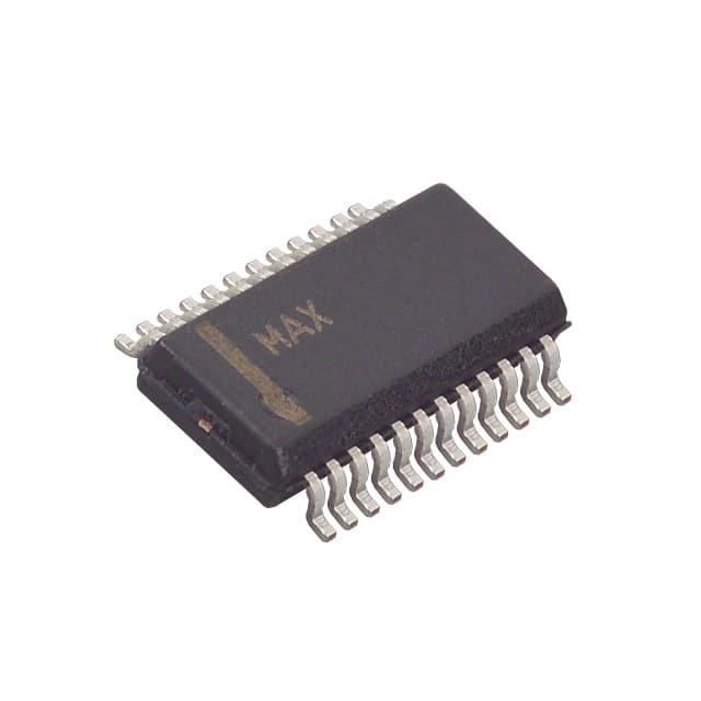
- Part No.:
- MAX7349AEG+
- Manufacturer:
- Analog Devices Inc./Maxim Integrated
- Category:
- Specialized
- Package:
- 24-SSOP (0.154", 3.90mm Width)
- Datasheet:
-
 MAX7349AEG+.pdf
- Description:
- IC INTERFACE SPECIALIZED 24QSOP
- Quantity:
- Payment:

- Shipping:

Inventory:772
Please send an inquiry. Send us your inquiry, and we will respond immediately.
Product details
Overview
MAX7349AEG+ from Maxim Integrated is a 24-pin QSOP I²C key-switch and sounder controller IC that monitors up to 64 metallic or resistive switches (≤1kΩ), debounces key events with user-configurable 9–40ms timing, maintains an 8-deep FIFO, and integrates a programmable piezo tone generator for key-click feedback or alarms. It operates from 2.4V to 3.6V across –40°C to +125°C and features six configurable open-drain GPOs plus an ALERT input.
For engineers reviewing the MAX7349AEG+ datasheet, MAX7349AEG+ pinout, MAX7349AEG+ application, or MAX7349AEG+ equivalent, this page delivers verified technical context, exact pin functions, real-world use cases in medical and industrial panels, and validated alternative parts - all grounded in Maxim's official documentation and electrical specifications.
Technical Context
The MAX7349AEG+ implements static matrix scanning (not dynamic row/column multiplexing) to minimize EMI emissions during key monitoring. Its dual-function architecture separates key-scan control (with interrupt/FIFO management) from independent sounder control (using a dedicated slave address and double-buffered command queue).
It supports four I²C slave addresses via AD0 configuration (GND/V+/SDA/SCL), includes selectable 20–68ms bus timeout, and allows INT pin reconfiguration as a general-purpose open-drain output. The sounder output is push-pull capable of driving piezo transducers, relays, or lamps at frequencies from 523.25Hz to 2637Hz with ±1.2% accuracy.
Key Specifications
| Parameter | Value and Actual Design Meaning |
|---|---|
| Supply Voltage | 2.4V to 3.6V - compatible with modern low-voltage microcontrollers and battery-backed systems. |
| Key Switch Capacity | Up to 64 keys - achieved via 8-row × 8-column matrix with static monitoring and no scan clock noise. |
| FIFO Depth | 8 debounced key events - enables burst key-press handling without host polling overhead. |
| Debounce Time | User-configurable 9ms to 40ms - prevents false triggers from mechanical switch bounce. |
| Sounder Frequencies | 14 programmable tones (523.25Hz–2637Hz) - covers musical 5th octave plus seven additional notes. |
| I²C Speed | Up to 400kbps - supports fast configuration and event retrieval in real-time HMI systems. |
| Shutdown Current | ≤10µA - enables ultra-low-power operation in always-on panel interfaces. |
Pinout & Package
MAX7349AEG+ is housed in a 24-pin QSOP package (package code E24-1), with exposed paddle internally connected to GND for thermal performance. Pin functions are validated per Maxim's official pin description table and schematic reference.
| Pin/Terminal | Circuit Role | Design Meaning |
|---|---|---|
| ROW0–ROW7 | Key matrix row inputs | Accept open-collector or pull-up switch returns; static monitoring eliminates scanning EMI. |
| COL0–COL7/PORT7 | Column outputs or GPOs | Configurable as key matrix column drivers or open-drain logic outputs (up to 6 usable as GPOs). |
| SOUNDER | Piezo/relay/lamp driver | Push-pull output supporting 14 programmable tones or DC-level control (high/low for duration). |
| INT | Interrupt or GPO | Active-low open-drain interrupt by default; reconfigurable as seventh GPO when not used for alerts. |
| ALERT | Dedicated logic input | Triggers interrupt and/or sound on falling edge; readable as status bit - MAX7349-exclusive feature. |
| SDA/SCL/AD0 | I²C interface & address select | 5.5V-tolerant SDA/SCL; AD0 sets one of four I²C addresses (GND/V+/SDA/SCL). |
Key Features
| Feature | Design Value |
|---|---|
| Low-EMI static key scanning | Eliminates high-frequency switching noise from dynamic matrix scanning - critical for sensitive medical instrumentation. |
| Configurable autorepeat | Adjustable delay (125–1000ms) and rate (31–250ms) - enables intuitive UI behavior for menu navigation. |
| Dual I²C slave addressing | Separate addresses for key-scan (0x48–0x4F) and sounder (0x40–0x47) - enables concurrent register access without conflict. |
| Programmable sounder duration | Seven binary steps from 15.625ms to 1s - supports precise tactile feedback timing or alarm pulse widths. |
| Alert-triggered audio/interrupt | Hardware-level response to external logic edge - enables immediate system notification without host polling. |
Applications
| Medical Instrument Panels | Industrial Control Consoles |
|---|---|
|
Use Scenario: Front-panel keypad on infusion pumps or diagnostic analyzers requiring EMI-safe operation near analog signal paths. IC Role / Device Role / Timing Role: Key-scan controller with static matrix monitoring and FIFO-based event buffering; sounder provides audible confirmation synchronized to key press. Use Value: Eliminates scan-clock interference with precision ADCs and sensor front-ends while delivering responsive, feedback-rich HMI. |
Use Scenario: Operator interface on PLC-mounted HMIs in factory automation, where metal-key durability and noise immunity are essential. IC Role / Device Role / Timing Role: Centralized key management unit interfacing 64-button panels; ALERT input tied to emergency stop circuits for instant tone + interrupt. Use Value: Reduces MCU GPIO count and firmware complexity while enabling fail-safe audible/visual alerting without software latency. |
| Security Access Keypads | Test & Measurement Equipment |
|
Use Scenario: Tamper-resistant entry keypad for biometric door controllers operating in wide temperature ranges. IC Role / Device Role / Timing Role: Secure key monitoring with debounce and autorepeat; sounder generates distinct tones for valid/invalid entries. Use Value: Ensures reliable key detection across –40°C to +125°C and provides immediate, non-visual feedback for accessibility compliance. |
Use Scenario: Front-panel controls on oscilloscopes or spectrum analyzers needing silent, low-noise operation near RF sections. IC Role / Device Role / Timing Role: EMI-optimized key scanner isolating digital switching noise from analog measurement circuitry. Use Value: Prevents spurious signals from key scanning from corrupting sub-mV measurements or GHz-range signal integrity. |
Equivalent & Alternatives
The following parts are listed as comparable options for similar key-switch and sounder controller applications.
| Alternative Part | Technical Difference | Application Difference | Selection Advice |
|---|---|---|---|
| MAX7348AEP+ | Monitors up to 40 keys; lacks ALERT input; only 3 GPOs (vs. 6); same 24-pin QSOP footprint not applicable - uses 20-pin QSOP. | Best suited for smaller keypads where full 64-key capacity and external alert triggering are unnecessary. | Select MAX7348AEP+ when reducing component count and cost is prioritized over maximum key density and alert integration. |
| TCA9554PWR | I²C 8-bit GPIO expander only - no key-scan logic, no debounce, no FIFO, no sounder, no ALERT input. | Requires full firmware implementation of key scanning, debouncing, and tone generation - increases MCU load and BOM count. | Choose TCA9554PWR only if discrete GPIO expansion suffices and all key/sounder functionality is handled in software. |
Compared with MAX7349AEG+, MAX7348AEP+ reduces key capacity and removes ALERT functionality but lowers cost and power; TCA9554PWR offers no integrated key-scan or audio capability, shifting full responsibility to the host MCU and increasing design effort and latency.
Availability
MAX7349AEG+ is available at Aetrix Electronics and suitable for medical instrument panels, industrial control consoles, security access keypads, and test & measurement equipment requiring stable component supply across extended temperature and long product lifecycles.
Supply support for MAX7349AEG+ includes scheduled delivery planning, volume procurement assistance, BOM continuity management, traceable sourcing, and lifecycle availability coordination for OEM customers, industrial embedded developers, connected-device designers, and electronics production programs.
Manufacturer
Maxim Integrated (now part of Analog Devices) designs precision analog and mixed-signal ICs for demanding industrial, medical, and automotive applications - emphasizing reliability, low noise, and extended temperature operation.
The MAX7349AEG+ belongs to Maxim's key-scan and sounder controller product line, engineered specifically for EMI-sensitive human-machine interfaces requiring integrated debouncing, FIFO buffering, and programmable audio feedback without MCU resource overhead.
FAQ
What is the maximum number of keys supported by the MAX7349AEG+?
The MAX7349AEG+ supports up to 64 key switches arranged in an 8×8 matrix. This capacity is achieved using static row/column monitoring - not time-multiplexed scanning - ensuring minimal EMI generation. Each key can be metallic or resistive (up to 1kΩ), and all key events are debounced and queued in an 8-deep FIFO. The MAX7349AEG+ is the highest-capacity variant in the MAX7347/MAX7348/MAX7349 family.
Does the MAX7349AEG+ include a built-in tone generator?
Yes, the MAX7349AEG+ integrates a dedicated piezo sounder controller with 14 programmable musical frequencies ranging from 523.25Hz to 2637Hz - covering the entire 5th musical octave plus seven additional notes. It supports automatic key-click sounds, single/dual-tone alarms, and DC-level output for relays or lamps. The sounder operates via a separate I²C slave address and uses double-buffered commands to eliminate click artifacts during transitions.
What is the function of the ALERT pin on the MAX7349AEG+?
The ALERT pin on the MAX7349AEG+ is a dedicated logic input that triggers both an interrupt and/or a programmable sound on each falling edge - a feature exclusive to the MAX7349AEG+ (not present on MAX7347/MAX7348). Its state is readable as a status bit, and it can be tied to external safety circuits (e.g., emergency stop buttons) to initiate immediate audible and processor-notified responses without host polling.
Can the INT pin on the MAX7349AEG+ be used as a general-purpose output?
Yes, the INT pin on the MAX7349AEG+ is configurable as either an active-low open-drain interrupt output or a general-purpose open-drain logic output (GPO). When repurposed as a GPO, it adds a seventh controllable output alongside the six COL/PORT pins. This flexibility allows designers to trade interrupt functionality for additional LED drive or system signaling capability - all under register control without hardware change.
What are the I²C voltage and speed specifications for the MAX7349AEG+?
The MAX7349AEG+ supports a 400kbps I²C interface with 5.5V-tolerant SDA and SCL pins - enabling direct connection to 5V microcontrollers without level shifters. Its I²C implementation includes selectable bus timeout (20–68ms), four slave address options (via AD0 pin), and dual-address architecture: one for key-scan registers (0x48–0x4F) and another for sounder control (0x40–0x47). This ensures robust, conflict-free communication in multi-device systems.
MAX7349AEG+ Specifications
- Product attributes
- Attribute value
- Manufacturer:
- Analog Devices Inc./Maxim Integrated
- Series:
- -
- Package/Case:
- 24-SSOP (0.154", 3.90mm Width)
- Packaging:
- Tube
- Product Status:
- Not For New Designs
- Applications:
- Sound Cards, Players, Recorders
- Interface:
- I2C
- Voltage - Supply:
- 2.4V ~ 3.6V
- Supplier Device Package:
- 24-QSOP
- Grade:
- -
- Qualification:
- -
- Mounting Type:
- Surface Mount
MAX7349AEG+ FAQ
1.How can I place an order for MAX7349AEG+ through Aetrix?
Please submit a Request for Quotation (RFQ) for MAX7349AEG+ on Aetrix. Our sales agent will provide a competitive quotation and guide you through the order confirmation once you accept the terms.
2.Are the price and stock information for MAX7349AEG+ reliable?
The price and inventory of MAX7349AEG+ are updated periodically and may fluctuate due to market conditions. Stock and pricing data are typically refreshed every 24 hours. Quotation validity for MAX7349AEG+ is usually 5 days.
3.What payment methods are accepted for MAX7349AEG+?
We accept Wire Transfer, PayPal, Credit Card, Western Union, MoneyGram, and Escrow for MAX7349AEG+ transactions.
Note: Certain payment methods may incur a processing fee.
4.How is shipping managed for MAX7349AEG+?
MAX7349AEG+ orders can be shipped via leading logistics carriers, including DHL, UPS, FedEx, TNT, or Registered Mail.
Once your MAX7349AEG+ order is processed, you will receive an email with the shipment details and tracking number.
Note: Tracking information may take up to 24 hours to appear. Express delivery typically takes 3–5 business days.
5.How can I obtain technical support or documentation for MAX7349AEG+?
For technical support, including MAX7349AEG+ datasheets, pinout diagrams, or application guidance, please contact our engineering support team. They can provide detailed documentation and assistance for your MAX7349AEG+ requirements.
6.How does Aetrix verify that MAX7349AEG+ is sourced from the original manufacturer or authorized distributors?
All MAX7349AEG+ products on Aetrix are procured from qualified distributors and authorized channels. Our dedicated quality assurance team conducts strict verification, including traceability checks and, if necessary, third-party testing. This ensures that MAX7349AEG+ meets industry standards.
7.What is the process for return or replacement of MAX7349AEG+?
All MAX7349AEG+ units undergo pre-shipment inspection (PSI). If there is an issue with MAX7349AEG+, returns or replacements are accepted under the following conditions:
1.Quantity discrepancies, incorrect items, or visible external defects (such as breakage or corrosion), acknowledged by Aetrix.
2.The issue is reported within 90 days of delivery.
3.The MAX7349AEG+ part is unused and in its original packaging.
Return procedure for MAX7349AEG+:
1.Submit a request within 90 days.
2.Obtain a Return Material Authorization (RMA) from Aetrix.
MAX7349AEG+ Tags

-
NVT4857UKAZ
NXP Semiconductors

-
TCA8418RTWR
Texas Instruments

-
PCA9546APWR
Texas Instruments

-
MD0100N8-G
Microchip Technology

-
PCA9548APW,118
NXP Semiconductors

-
PCA9540BDP,118
NXP Semiconductors

-
PCA9548APWR
Texas Instruments

-
PCA9546APW,118
NXP Semiconductors

-
PTN3360DBS,518
NXP Semiconductors

-
PCA9546ABS,118
NXP Semiconductors

-
PCA9518PWR
Texas Instruments

-
PCA9545APW,118
NXP Semiconductors
Tech Hub

A practical engineering guide to 3.3V and 5V logic compatibility, input thresholds, resistor dividers, translator ICs, MOSFET level shifting, I2C pull-ups, timing limits and power-sequencing risks.

The 74HC595 uses push-pull logic outputs, while the TPIC6B595 uses 50 V open-drain DMOS sinks for higher-power loads. This guide compares timing, current limits, 3.3 V interfacing, load wiring, thermal…

The 74HC595 converts serial data into eight stable parallel outputs. This guide covers pin functions, shift and storage timing, OE and MR behavior, drive-current limits, cascading, voltage compatibilit…

A technical comparison of level-sensitive latches and edge-triggered flip-flops, covering timing windows, setup and hold limits, master–slave operation, time borrowing, race-through, HDL inference and…

A D latch stores one bit while Enable controls when data can pass. This reference covers gate-level operation, truth tables, transparency, setup and hold timing, LE versus OE, common ICs and practical …

An SR latch stores one bit through cross-coupled feedback. This engineering reference covers NOR and NAND implementations, truth tables, forbidden-state recovery, gated operation, switch debouncing, fa…

Latch circuits retain one bit through feedback. This technical reference covers SR and D latches, truth tables, transparency, timing limits, latch-versus-flip-flop behavior, applications and common log…

An engineering guide to LED driver operation, constant-current and constant-voltage outputs, linear and switching topologies, dimming, IC selection, calculations, replacement compatibility, and fault c…

Operational amplifier guide covering op amp basics, feedback, ideal vs real op amps, common configurations, buffer circuits, offset, bias current, gain-bandwidth, slew rate, rail-to-rail limits and sel…

Jumper cables guide covering safe connection order, red and black clamp placement, final ground connection, cable gauge, length, clamp quality, copper vs CCA cables, jump starter comparison and battery…


