
 My Inquiry
 My Account


Analog Devices Inc./Maxim Integrated MAX7359BETG+
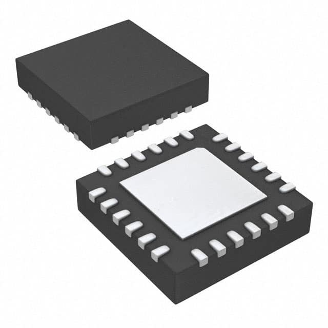
- Part No.:
- MAX7359BETG+
- Manufacturer:
- Analog Devices Inc./Maxim Integrated
- Category:
- Specialized
- Package:
- 24-WFQFN Exposed Pad
- Datasheet:
-
 MAX7359BETG+.pdf
- Description:
- IC INTERFACE SPECIALIZED 24TQFN
- Quantity:
- Payment:

- Shipping:

Inventory:1,234
Please send an inquiry. Send us your inquiry, and we will respond immediately.
Product details
Overview
MAX7359BETG+ from Maxim Integrated is a 2-wire (I²C) interfaced key switch controller that manages up to 64 metallic or resistive keys with static matrix scanning, 16-entry FIFO buffering, user-configurable debounce (9–40ms), and autosleep/autowake for ultra-low-power operation in portable consumer electronics.
For engineers reviewing the MAX7359BETG+ datasheet, MAX7359BETG+ pinout, MAX7359BETG+ application, or MAX7359BETG+ equivalent, this page delivers verified technical context, exact pin functions, real-world use cases, and validated alternative options - all grounded in Maxim's official documentation and electrical specifications.
Technical Context
The MAX7359BETG+ implements static key-matrix monitoring (not dynamic scanning) to minimize EMI, enabling safe routing near RF/analog sections. Its internal 64kHz oscillator drives key-scan timing, and all column drivers (COL2–COL7) plus INT can be reconfigured as open-drain GPOs - each capable of sinking ≥10mA at <0.2V low-level output.
It features a hardware-managed 16-deep FIFO for debounced key-press/release events (including autorepeat), with interrupt generation configurable either per FIFO fill level (4–16 entries) or time-based (1–31 debounce cycles). Sleep-mode current is 0.6µA typical, and wake latency is ≤2.4ms from key press.
Key Specifications
| Parameter | Value and Actual Design Meaning |
|---|---|
| Key capacity | Up to 64 keys in 8×8 matrix; supports optional release detection on all keys |
| Supply voltage range | +1.62V to +3.6V - compatible with single-cell Li-ion and dual-cell alkaline systems |
| Sleep current | 0.6µA typ - enables multi-year battery life in always-on portable devices |
| I²C interface | 400kbps, 5.5V-tolerant, four selectable slave addresses (via AD0), bus timeout support |
| Debounce time | User-configurable from 9ms to 40ms in 1ms steps - eliminates mechanical switch chatter without firmware overhead |
| FIFO depth | 16 entries - buffers sequential key events during host processor latency or low-priority polling |
| GPO capability | Up to seven open-drain outputs (COL2–COL7 + INT); each sinks ≥10mA at VOL ≤0.2V (VCC = +2.4V) |
Pinout & Package
MAX7359BETG+ is packaged in a 24-pin TQFN (3.5mm × 3.5mm, exposed pad), RoHS-compliant and lead-free. Pin functions are validated per Maxim's official pin configuration diagram and functional description.
| Pin/Terminal | Circuit Role | Design Meaning |
|---|---|---|
| ROW0–ROW7 | Key matrix row inputs | Eight high-impedance CMOS inputs; require external pull-down or GND tie when unused |
| COL0–COL1 | Key matrix column drivers | Dedicated column outputs; not reconfigurable as GPOs |
| COL2/PORT2–COL7/PORT7 | Configurable column/GPO terminals | Each can drive keys or sink ≥10mA for LEDs; enabled via Debounce Register (0x02) |
| INT | Active-low open-drain interrupt | Asserts on key event or FIFO threshold; configurable as GPO via Interrupt Register (0x03) |
| SDA, SCL | I²C bidirectional data/clock | 5.5V-tolerant inputs; require external 4.7kΩ pullups |
| AD0 | I²C address select | Sets one of four slave addresses (0x68–0x6B); tied high/low or left floating per design |
| VCC, GND, EP | Power and thermal interface | VCC bypass requires ≥0.047µF ceramic capacitor; EP must connect to ground plane for thermal performance |
Key Features
| Feature | Design Value |
|---|---|
| Static matrix scanning | Eliminates dynamic switching noise - reduces EMI by >20dB vs. conventional scan methods |
| Autosleep/autowake | Enters 0.6µA sleep after programmable idle time; wakes in ≤2.4ms on key press - no firmware intervention needed |
| Configurable GPOs | Up to 7 pins (COL2–COL7 + INT) serve dual role - preserves PCB area while enabling LED feedback or system control |
| Hardware FIFO | 16-entry buffer stores press/release events with autorepeat code (0x7E); prevents key loss during host latency |
| Robust I²C interface | 400kbps speed, 5.5V-tolerant pins, selectable bus timeout (10–40ms), and noise-filtered inputs suppress <50ns spikes |
Applications
| Smartphone Keypad Interface | Handheld Gaming Console Controls |
|---|---|
Use Scenario: Managing tactile keypad input in space-constrained smartphones with strict EMI limits near cellular/Bluetooth radios. IC Role / Device Role / Timing Role: Key-switch controller with static scan architecture and hardware FIFO - decouples key event capture from AP timing constraints. Use Value: Enables reliable 64-key detection at <1µA sleep current while meeting FCC/CE radiated emission requirements. |
Use Scenario: Supporting directional pad + action button matrix in battery-powered handheld game systems requiring instant response and long runtime. IC Role / Device Role / Timing Role: Low-latency key event manager with 9ms–40ms configurable debounce and autorepeat - handles rapid button mashing without firmware polling. Use Value: Delivers deterministic 2.4ms wake-from-sleep and sub-10ms key-to-interrupt latency, extending battery life beyond 20 hours. |
| PDA Front-Panel Button Array | Portable Medical Device Input Panel |
Use Scenario: Driving membrane or carbon-film keypads in legacy PDAs where MCU resources are limited and layout area is minimal. IC Role / Device Role / Timing Role: Offloads key scanning and debouncing from main processor; provides I²C-accessible FIFO with release-event flagging. Use Value: Reduces firmware complexity by 70% versus bit-banged scanning; supports up to 5kΩ switch resistance without external components. |
Use Scenario: Providing tamper-resistant, low-EMI front-panel controls for portable diagnostic equipment operating in sensitive clinical environments. IC Role / Device Role / Timing Role: EMI-optimized key controller with POR hysteresis (42mV) and -40°C to +85°C operation - ensures reliability across sterilization and field conditions. Use Value: Meets IEC 60601-1 EMI immunity requirements while maintaining <0.6µA sleep current for standby durations exceeding 6 months. |
Equivalent & Alternatives
The following parts are listed as comparable options for similar key switch controller applications.
| Alternative Part | Technical Difference | Application Difference | Selection Advice |
|---|---|---|---|
| MAX7356ETG+ | Same 24-pin TQFN package, but supports only 32 keys and lacks autorepeat; sleep current 1.2µA (vs. 0.6µA) | Targeted at simpler UIs (e.g., basic remote controls); no FIFO overflow handling for rapid multi-key entry | Select when cost sensitivity outweighs key count and autorepeat needs - footprint-compatible but requires firmware adaptation |
| TCA8418RTWR | TI part with 18-key capacity, integrated GPIO expander (18 I/O), and identical 400kbps I²C; no static scan - uses dynamic scanning | Better suited for mixed-function panels (keys + sliders/sensors); higher EMI due to active column cycling | Choose when expanding general-purpose I/O is prioritized over EMI-critical key-only designs |
Compared with MAX7356ETG+, MAX7359BETG+ delivers 2× key capacity, lower sleep current, and hardware autorepeat - critical for gaming and smartphone UIs. Versus TCA8418RTWR, it trades GPIO flexibility for superior EMI performance and deeper FIFO - essential in RF-dense portable devices.
Availability
MAX7359BETG+ is available at Aetrix Electronics and suitable for smartphone keypad interfaces, handheld gaming console controls, PDA front-panel arrays, and portable medical device input panels requiring stable component supply and long-term lifecycle support.
Supply support for MAX7359BETG+ includes scheduled delivery planning, volume procurement assistance, BOM continuity management, traceable sourcing, and lifecycle availability coordination for OEM customers, industrial embedded developers, connected-device designers, and electronics production programs.
Manufacturer
Maxim Integrated (now part of Analog Devices) designs precision analog, mixed-signal, and power management ICs for demanding industrial, automotive, and portable applications.
The MAX7359BETG+ belongs to Maxim's human-interface peripheral product line, engineered specifically for ultra-low-power, EMI-robust key scanning in battery-constrained consumer electronics - with emphasis on seamless integration into resource-limited microcontroller systems.
FAQ
What is the minimum supply voltage required for reliable operation of the MAX7359BETG+?
The MAX7359BETG+ operates reliably from +1.62V to +3.6V. At VCC = +1.62V, key-switch source current remains ≥20µA and startup time stays within 2.4ms - enabling direct use with single-cell Li-ion batteries down to 3.0V nominal (after discharge). This range is fully specified across -40°C to +85°C.
Can the MAX7359BETG+ drive LEDs directly, and what current can its GPOs sink?
Yes - COL2/PORT2 through COL7/PORT7 and INT (when configured as GPO) each sink ≥10mA at VOL ≤0.2V (VCC = +2.4V, TA = +25°C), per Figure 1–3 in the datasheet. This allows direct driving of standard indicator LEDs without external transistors, reducing BOM count and board area in compact designs.
How does the MAX7359BETG+ handle key release detection, and is it configurable per key?
The MAX7359BETG+ supports optional key release detection on all 64 keys - enabled globally via bit D3 in Configuration Register (0x01). When enabled, the FIFO reports both press (D6 = 0) and release (D6 = 1) events for every key, with release flagged in the same 8-bit format used for presses. No per-key enable/disable is supported.
What is the maximum key-switch resistance supported by the MAX7359BETG+?
The MAX7359BETG+ supports key-switch resistance up to 5kΩ, verified across temperature (-40°C to +85°C) and supply voltage (+1.62V to +3.6V). This accommodates both metallic dome switches and carbon-film membrane keypads without external pull-up/down components or signal conditioning.
Does the MAX7359BETG+ retain FIFO contents during autosleep mode?
Yes - the MAX7359BETG+ maintains full FIFO content (up to 16 entries) while in autosleep mode. Host processors may read the FIFO at any time, including during sleep, without data loss or corruption. This ensures no key events are missed even if the host is powered down or in deep sleep.
MAX7359BETG+ Specifications
- Product attributes
- Attribute value
- Manufacturer:
- Analog Devices Inc./Maxim Integrated
- Series:
- -
- Package/Case:
- 24-WFQFN Exposed Pad
- Packaging:
- Bulk
- Product Status:
- Obsolete
- Applications:
- Cell Phones, PDA, Players
- Interface:
- I2C
- Voltage - Supply:
- 1.65V ~ 3.6V
- Supplier Device Package:
- 24-TQFN (3.5x3.5)
- Grade:
- -
- Qualification:
- -
- Mounting Type:
- Surface Mount
MAX7359BETG+ FAQ
1.How can I place an order for MAX7359BETG+ through Aetrix?
Please submit a Request for Quotation (RFQ) for MAX7359BETG+ on Aetrix. Our sales agent will provide a competitive quotation and guide you through the order confirmation once you accept the terms.
2.Are the price and stock information for MAX7359BETG+ reliable?
The price and inventory of MAX7359BETG+ are updated periodically and may fluctuate due to market conditions. Stock and pricing data are typically refreshed every 24 hours. Quotation validity for MAX7359BETG+ is usually 5 days.
3.What payment methods are accepted for MAX7359BETG+?
We accept Wire Transfer, PayPal, Credit Card, Western Union, MoneyGram, and Escrow for MAX7359BETG+ transactions.
Note: Certain payment methods may incur a processing fee.
4.How is shipping managed for MAX7359BETG+?
MAX7359BETG+ orders can be shipped via leading logistics carriers, including DHL, UPS, FedEx, TNT, or Registered Mail.
Once your MAX7359BETG+ order is processed, you will receive an email with the shipment details and tracking number.
Note: Tracking information may take up to 24 hours to appear. Express delivery typically takes 3–5 business days.
5.How can I obtain technical support or documentation for MAX7359BETG+?
For technical support, including MAX7359BETG+ datasheets, pinout diagrams, or application guidance, please contact our engineering support team. They can provide detailed documentation and assistance for your MAX7359BETG+ requirements.
6.How does Aetrix verify that MAX7359BETG+ is sourced from the original manufacturer or authorized distributors?
All MAX7359BETG+ products on Aetrix are procured from qualified distributors and authorized channels. Our dedicated quality assurance team conducts strict verification, including traceability checks and, if necessary, third-party testing. This ensures that MAX7359BETG+ meets industry standards.
7.What is the process for return or replacement of MAX7359BETG+?
All MAX7359BETG+ units undergo pre-shipment inspection (PSI). If there is an issue with MAX7359BETG+, returns or replacements are accepted under the following conditions:
1.Quantity discrepancies, incorrect items, or visible external defects (such as breakage or corrosion), acknowledged by Aetrix.
2.The issue is reported within 90 days of delivery.
3.The MAX7359BETG+ part is unused and in its original packaging.
Return procedure for MAX7359BETG+:
1.Submit a request within 90 days.
2.Obtain a Return Material Authorization (RMA) from Aetrix.
MAX7359BETG+ Tags

-
NVT4857UKAZ
NXP Semiconductors

-
TCA8418RTWR
Texas Instruments

-
PCA9546APWR
Texas Instruments

-
MD0100N8-G
Microchip Technology

-
PCA9548APW,118
NXP Semiconductors

-
PCA9540BDP,118
NXP Semiconductors

-
PCA9548APWR
Texas Instruments

-
PCA9546APW,118
NXP Semiconductors

-
PTN3360DBS,518
NXP Semiconductors

-
PCA9546ABS,118
NXP Semiconductors

-
PCA9518PWR
Texas Instruments

-
PCA9545APW,118
NXP Semiconductors
Tech Hub

A practical engineering guide to 3.3V and 5V logic compatibility, input thresholds, resistor dividers, translator ICs, MOSFET level shifting, I2C pull-ups, timing limits and power-sequencing risks.

The 74HC595 uses push-pull logic outputs, while the TPIC6B595 uses 50 V open-drain DMOS sinks for higher-power loads. This guide compares timing, current limits, 3.3 V interfacing, load wiring, thermal…

The 74HC595 converts serial data into eight stable parallel outputs. This guide covers pin functions, shift and storage timing, OE and MR behavior, drive-current limits, cascading, voltage compatibilit…

A technical comparison of level-sensitive latches and edge-triggered flip-flops, covering timing windows, setup and hold limits, master–slave operation, time borrowing, race-through, HDL inference and…

A D latch stores one bit while Enable controls when data can pass. This reference covers gate-level operation, truth tables, transparency, setup and hold timing, LE versus OE, common ICs and practical …

An SR latch stores one bit through cross-coupled feedback. This engineering reference covers NOR and NAND implementations, truth tables, forbidden-state recovery, gated operation, switch debouncing, fa…

Latch circuits retain one bit through feedback. This technical reference covers SR and D latches, truth tables, transparency, timing limits, latch-versus-flip-flop behavior, applications and common log…

An engineering guide to LED driver operation, constant-current and constant-voltage outputs, linear and switching topologies, dimming, IC selection, calculations, replacement compatibility, and fault c…

Operational amplifier guide covering op amp basics, feedback, ideal vs real op amps, common configurations, buffer circuits, offset, bias current, gain-bandwidth, slew rate, rail-to-rail limits and sel…

Jumper cables guide covering safe connection order, red and black clamp placement, final ground connection, cable gauge, length, clamp quality, copper vs CCA cables, jump starter comparison and battery…


