
 My Inquiry
 My Account


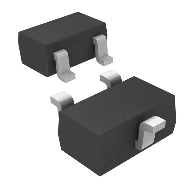
Analog Devices Inc./Maxim Integrated MAX7375AXR105+T
- Part No.:
- MAX7375AXR105+T
- Manufacturer:
- Analog Devices Inc./Maxim Integrated
- Category:
- Oscillators
- Package:
- SC-70, SOT-323
- Datasheet:
-
 MAX7375AXR105+T.pdf
- Description:
- MEMS OSC XO 1.0000MHZ CMOS SMD
- Quantity:
- Payment:

- Shipping:

Inventory:3,834
Please send an inquiry. Send us your inquiry, and we will respond immediately.
Product details
Overview
MAX7375AXR105+T from Maxim Integrated is a factory-trimmed 1.00MHz silicon oscillator in SC70-3 package, delivering rail-to-rail 50% duty cycle square-wave output with ±2% initial accuracy and ±50ppm/°C temp drift. It operates from 2.7V to 5.5V, draws 0.55–1.1mA supply current, and starts up in 5µs - designed as a drop-in replacement for ceramic resonators and crystals in microcontroller clocking for white goods and industrial controls.
For engineers reviewing the MAX7375AXR105+T datasheet, MAX7375AXR105+T pinout, MAX7375AXR105+T application, or MAX7375AXR105+T equivalent, key selection criteria include its vibration-immune oscillator architecture, 160psP-P jitter at 8MHz (scaled), push-pull CMOS output driving capability, and guaranteed -40°C to +125°C operation without external components.
Technical Context
The MAX7375AXR105+T uses a fully integrated BiCMOS oscillator core generating frequency directly-no PLL, no crystal load capacitors, no biasing network. Its push-pull CLOCK output drives 1kΩ to GND or 500Ω to V+, maintaining stable logic levels across full voltage and temperature range.
Startup occurs within 5µs after V+ exceeds ~1.65V; output remains glitch-free during power-on/off transitions. Jitter is measured peak-to-peak over 20s with 500MHz scope, and scales inversely with frequency-so 1MHz operation yields lower absolute jitter than higher-frequency variants.
Key Specifications
| Parameter | Value and Actual Design Meaning |
|---|---|
| Output Frequency | 1.00MHz nominal - factory-trimmed, no adjustment required |
| Initial Accuracy | ±2% at +25°C, V+ = 3.0V - enables reliable timing without calibration |
| Temp Drift | ±50ppm/°C - ensures stable clocking across -40°C to +125°C |
| Supply Current | 0.55–1.1mA at 1MHz - low power suitable for battery-backed or energy-conscious systems |
| Output Drive | ±10mA push-pull - directly interfaces with µC clock inputs without level-shifting or buffering |
| Rise/Fall Time | 5ns / 2.5ns - fast edges reduce EMI susceptibility and improve signal integrity |
| Duty Cycle | 45–57% - rail-to-rail square wave optimized for digital clock input compatibility |
Pinout & Package
Package: SC70-3 (3-pin surface-mount, 1.25mm × 0.85mm × 0.55mm body, 0.65mm pitch). Pin 1 = V+, Pin 2 = CLOCK, Pin 3 = GND.
| Pin/Terminal | Circuit Role | Design Meaning |
|---|---|---|
| V+ | Positive supply input | Accepts 2.7V–5.5V; powers internal oscillator and output stage |
| CLOCK | CMOS push-pull clock output | Drives µC/UART clock input directly; no external load caps or termination needed |
| GND | Ground reference | Return path for supply and output current; must be low-impedance for jitter control |
Key Features
| Feature | Design Value |
|---|---|
| No external components | Eliminates load capacitors, feedback resistors, and bias networks required by crystal circuits |
| Vibration/EMI immunity | Monolithic silicon design avoids high-impedance nodes and mechanical resonance of crystals |
| Fast startup (5µs) | Enables immediate µC execution after power-up - no wait-state delays required |
| Rail-to-rail output | Ensures full logic swing across supply range, compatible with 3.3V and 5V µC clock inputs |
| Low-jitter timing | 160psP-P at 8MHz (scaled to ~320psP-P at 1MHz) - meets UART and synchronous peripheral timing budgets |
Applications
| White Goods Control Systems | Industrial Microcontroller Clocking |
|---|---|
|
Use Scenario: Timing reference for MCU-based washing machine control boards operating in humid, vibration-prone environments. IC Role / Device Role / Timing Role: Primary system clock source replacing ceramic resonator; drives 8-bit/32-bit MCU core and peripherals. Use Value: Immunity to cabinet vibration and steam-induced condensation eliminates clock failure modes seen with ceramic resonators. |
Use Scenario: Clock generation for programmable logic controllers (PLCs) deployed in factory automation with wide ambient temperature swings. IC Role / Device Role / Timing Role: Stable 1MHz clock feeding real-time interrupt timers and serial communication modules. Use Value: Guaranteed -40°C to +125°C operation and ±50ppm/°C drift ensure deterministic timing across thermal cycling. |
| Smart Appliance User Interfaces | Portable Diagnostic Equipment |
|
Use Scenario: Clock source for touch-screen controller and display driver in refrigerator control panels exposed to kitchen EMI. IC Role / Device Role / Timing Role: Synchronous timing reference for SPI/I²C interface between MCU and display ICs. Use Value: Low EMI susceptibility prevents display flicker or touch response lag caused by nearby microwave or motor noise. |
Use Scenario: Timing element in handheld medical diagnostic tools requiring low-power, rapid-start clocking for sensor sampling. IC Role / Device Role / Timing Role: System clock for ARM Cortex-M0+ MCU managing ADC acquisition and Bluetooth LE transmission. Use Value: 5µs startup and sub-1mA supply current enable responsive wake-from-sleep operation with minimal battery drain. |
Equivalent & Alternatives
The following parts are listed as comparable options for similar silicon oscillator applications.
| Alternative Part | Technical Difference | Application Difference | Selection Advice |
|---|---|---|---|
| SiT1533AI-H4-33E-1.000000G | 1.00MHz MEMS oscillator; ±10ppm initial accuracy; 1.62–3.63V supply; 1.2µA typical ICC | Ultra-low power and tighter accuracy, but requires 3.3V-only supply and lacks 5V tolerance | Select when ultra-low power and precision outweigh 5V compatibility and cost sensitivity |
| ABM3B-1.000MHZ-D2Y-T | 1.00MHz ceramic resonator; ±0.5% accuracy; requires external load capacitors and inverter circuit | Higher component count, larger footprint, and vibration sensitivity limit reliability in harsh environments | Select only for legacy designs where BOM cost is primary constraint and environmental robustness is secondary |
Compared with SiT1533AI-H4-33E-1.000000G and ABM3B-1.000MHZ-D2Y-T, the MAX7375AXR105+T offers superior 2.7–5.5V flexibility, integrated push-pull drive eliminating external circuitry, and proven vibration/EMI resilience - making it optimal for cost-sensitive, ruggedized embedded timing.
Availability
MAX7375AXR105+T is available at Aetrix Electronics and suitable for white goods control systems, industrial microcontroller clocking, and smart appliance user interfaces requiring stable component supply, long-term lifecycle support, and RoHS-compliant sourcing.
Supply support for MAX7375AXR105+T includes scheduled delivery planning, volume procurement assistance, BOM continuity management, traceable sourcing, and lifecycle availability coordination for OEM customers, industrial embedded developers, connected-device designers, and electronics production programs.
Manufacturer
Maxim Integrated (now part of Analog Devices) designs precision analog, mixed-signal, and timing solutions for demanding industrial, automotive, and computing applications.
The MAX7375AXR105+T belongs to Maxim's silicon oscillator product line, engineered to replace quartz and ceramic timing elements with monolithic, robust, and easy-to-integrate alternatives for microcontroller and UART clocking.
FAQ
What is the operating voltage range for the MAX7375AXR105+T?
The MAX7375AXR105+T operates from 2.7V to 5.5V DC, supporting 3V, 3.3V, and 5V systems without level-shifting. This wide supply range allows direct integration into mixed-voltage designs and ensures compatibility with legacy and modern microcontrollers alike. The MAX7375AXR105+T maintains specified accuracy and jitter performance across the full range.
Does the MAX7375AXR105+T require external load capacitors or biasing components?
No - the MAX7375AXR105+T is a fully integrated oscillator with no external components required. Unlike ceramic resonators or crystals, it contains all necessary circuitry on-die, including the oscillator core and push-pull output stage. This eliminates load capacitors, feedback resistors, and startup networks, simplifying layout and improving reliability in the MAX7375AXR105+T design.
What is the startup time of the MAX7375AXR105+T, and how does it affect system initialization?
The MAX7375AXR105+T achieves stable output within 5µs after V+ rises above ~1.65V. This fast startup enables immediate microcontroller execution without extended reset hold times. For robust boot sequencing, pair the MAX7375AXR105+T with a voltage supervisor that asserts reset until ≥5µs after V+ exceeds 2.7V - ensuring clock stability before firmware begins execution.
How does the MAX7375AXR105+T compare to quartz crystal oscillators in vibration-prone environments?
The MAX7375AXR105+T uses solid-state BiCMOS technology with no mechanical resonator, making it inherently immune to shock, vibration, and acoustic noise that degrade quartz crystal performance. In white goods or industrial equipment, this eliminates timing failures due to motor-induced vibration - a documented weakness of crystal-based clocks not shared by the MAX7375AXR105+T.
Is the MAX7375AXR105+T pin-compatible with other variants in the MAX7375 family?
Yes - all MAX7375 variants, including MAX7375AXR105+T, MAX7375AXR185+T, and MAX7375AXR805+T, share identical SC70-3 packaging and pinout (V+, CLOCK, GND). Frequency is factory-trimmed; no PCB changes are needed when upgrading or substituting within the family, provided supply and load requirements remain compatible for the MAX7375AXR105+T and target variant.
MAX7375AXR105+T Specifications
- Product attributes
- Attribute value
- Manufacturer:
- Analog Devices Inc./Maxim Integrated
- Series:
- MAX7375
- Package/Case:
- SC-70, SOT-323
- Packaging:
- Tape & Reel (TR)
- Product Status:
- Active
- Base Resonator:
- MEMS
- Type:
- XO (Standard)
- Frequency:
- 1 MHz
- Function:
- -
- Output:
- CMOS
- Voltage - Supply:
- 2.7V ~ 5.5V
- Frequency Stability:
- -
- Absolute Pull Range (APR):
- -
- Operating Temperature:
- -40°C ~ 125°C
- Spread Spectrum Bandwidth:
- -
- Current - Supply (Max):
- 1.1mA
- Ratings:
- -
- Mounting Type:
- Surface Mount
- Supplier Device Package:
- 4-VDFN (3.2x2.5)
- Size / Dimension:
- 0.087" L x 0.053" W (2.20mm x 1.35mm)
- Height - Seated (Max):
- 0.043" (1.10mm)
MAX7375AXR105+T FAQ
1.How can I place an order for MAX7375AXR105+T through Aetrix?
Please submit a Request for Quotation (RFQ) for MAX7375AXR105+T on Aetrix. Our sales agent will provide a competitive quotation and guide you through the order confirmation once you accept the terms.
2.Are the price and stock information for MAX7375AXR105+T reliable?
The price and inventory of MAX7375AXR105+T are updated periodically and may fluctuate due to market conditions. Stock and pricing data are typically refreshed every 24 hours. Quotation validity for MAX7375AXR105+T is usually 5 days.
3.What payment methods are accepted for MAX7375AXR105+T?
We accept Wire Transfer, PayPal, Credit Card, Western Union, MoneyGram, and Escrow for MAX7375AXR105+T transactions.
Note: Certain payment methods may incur a processing fee.
4.How is shipping managed for MAX7375AXR105+T?
MAX7375AXR105+T orders can be shipped via leading logistics carriers, including DHL, UPS, FedEx, TNT, or Registered Mail.
Once your MAX7375AXR105+T order is processed, you will receive an email with the shipment details and tracking number.
Note: Tracking information may take up to 24 hours to appear. Express delivery typically takes 3–5 business days.
5.How can I obtain technical support or documentation for MAX7375AXR105+T?
For technical support, including MAX7375AXR105+T datasheets, pinout diagrams, or application guidance, please contact our engineering support team. They can provide detailed documentation and assistance for your MAX7375AXR105+T requirements.
6.How does Aetrix verify that MAX7375AXR105+T is sourced from the original manufacturer or authorized distributors?
All MAX7375AXR105+T products on Aetrix are procured from qualified distributors and authorized channels. Our dedicated quality assurance team conducts strict verification, including traceability checks and, if necessary, third-party testing. This ensures that MAX7375AXR105+T meets industry standards.
7.What is the process for return or replacement of MAX7375AXR105+T?
All MAX7375AXR105+T units undergo pre-shipment inspection (PSI). If there is an issue with MAX7375AXR105+T, returns or replacements are accepted under the following conditions:
1.Quantity discrepancies, incorrect items, or visible external defects (such as breakage or corrosion), acknowledged by Aetrix.
2.The issue is reported within 90 days of delivery.
3.The MAX7375AXR105+T part is unused and in its original packaging.
Return procedure for MAX7375AXR105+T:
1.Submit a request within 90 days.
2.Obtain a Return Material Authorization (RMA) from Aetrix.
MAX7375AXR105+T Tags
-
ECS-2333-160-BN-TR
ECS Inc.
-
ECS-2333-240-BN-TR
ECS Inc.
-
KC2016Z25.0000C1KX00
KYOCERA AVX
-0.035-Thick.jpg)
-
ECS-2033-250-BN
ECS Inc.
-
O 25,0-JO32-B-1V3-1-T1-LF
Jauch Quartz
-
SIT1533AI-H4-DCC-32.768E
SiTime
-
ECS-2333-500-BN-TR
ECS Inc.
-
COM1305-50.000-EXT-T-TR
Raltron Electronics
-
SG-210STF 24.0000ML0
EPSON
-
ECS-3225MV-320-CN-TR
ECS Inc.
-
ECS-2033-240-BN
ECS Inc.
-
ECS-2333-120-BN-TR
ECS Inc.
Tech Hub

An SR latch stores one bit through cross-coupled feedback. This engineering reference covers NOR and NAND implementations, truth tables, forbidden-state recovery, gated operation, switch debouncing, fa…

Latch circuits retain one bit through feedback. This technical reference covers SR and D latches, truth tables, transparency, timing limits, latch-versus-flip-flop behavior, applications and common log…

An engineering guide to LED driver operation, constant-current and constant-voltage outputs, linear and switching topologies, dimming, IC selection, calculations, replacement compatibility, and fault c…

Operational amplifier guide covering op amp basics, feedback, ideal vs real op amps, common configurations, buffer circuits, offset, bias current, gain-bandwidth, slew rate, rail-to-rail limits and sel…

Jumper cables guide covering safe connection order, red and black clamp placement, final ground connection, cable gauge, length, clamp quality, copper vs CCA cables, jump starter comparison and battery…

LDO regulator guide covering low dropout voltage, power dissipation, thermal design, PSRR, output noise, capacitor stability, adjustable LDO circuits, LDO vs buck converter and datasheet selection chec…

Conditional Access Module guide covering CAM meaning, CI/CI+ interface, smart card authorization, DVB security workflow, TV and set-top box compatibility, internal electronics, ESD protection, connecto…

Guide to electronic component obsolescence covering EOL risk, PCN/PDN notices, last-time buy planning, replacement options, form-fit-function validation, counterfeit risk and BOM lifecycle management.

18650 battery guide covering lithium-ion cell basics, 3.6V/3.7V voltage, 4.2V charging, mAh and Wh capacity, protected cells, chargers, BMS, series-parallel packs, holders, welding and sourcing checks.…

Hall effect sensor guide covering working principle, linear and digital sensors, Arduino circuits, current sensing, speed detection, automotive applications, A3144 examples, signal filtering and datash…


