
 My Inquiry
 My Account


Analog Devices Inc./Maxim Integrated MAX7393ATTLY+
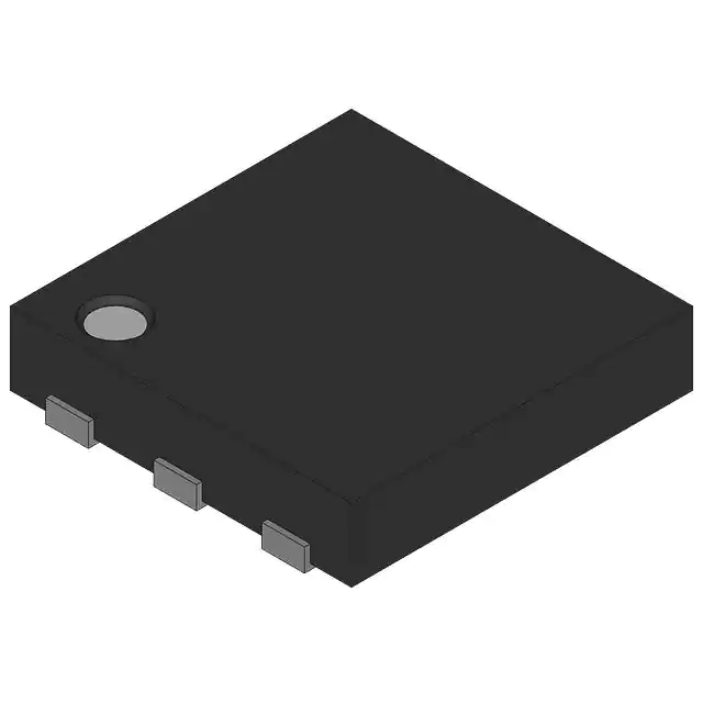
- Part No.:
- MAX7393ATTLY+
- Manufacturer:
- Analog Devices Inc./Maxim Integrated
- Category:
- Oscillators
- Package:
- 6-WDFN Exposed Pad
- Datasheet:
-
 MAX7393ATTLY+.pdf
- Description:
- OSC XO 922.0000 KHZ CMOS SMD
- Quantity:
- Payment:

- Shipping:

Inventory:3,398
Please send an inquiry. Send us your inquiry, and we will respond immediately.
Product details
Overview
The MAX7393ATTLY+ from Maxim Integrated is a precision silicon oscillator with autoenable functionality, replacing quartz crystals and ceramic resonators in +2.4V to +3.6V systems. It delivers factory-set 922kHz output with ±1.3% total accuracy over -40°C to +125°C (μDFN package), 5ns rise/fall time, and no external components required - ideal for space-constrained USB and white-goods timing applications.
For engineers reviewing the MAX7393ATTLY+ datasheet, MAX7393ATTLY+ pinout, MAX7393ATTLY+ application, or MAX7393ATTLY+ equivalent, key selection criteria include its autoenable (CLKIN) logic, μDFN-6 package footprint, ±1.3% wide-temp accuracy, and compatibility with microcontroller clock inputs without impedance matching or load capacitance.
Technical Context
The MAX7393ATTLY+ integrates a temperature-compensated BiCMOS oscillator core with autoenable logic that monitors CLKIN for an inverted feedback signal to autonomously enable/disable oscillation. Its push-pull CMOS CLOCK output drives 1kΩ to ground or 500Ω to VCC2 within 300mV of rails, eliminating termination needs.
It operates across -40°C to +125°C with dual supply rails (VCC and VCC2), both requiring 0.1µF ceramic decoupling to GND. Startup time is 2ms, and peak-to-peak jitter is not specified for 922kHz but is characterized at 16MHz (180ps) and 48MHz (140ps) for higher-frequency variants in the family.
Key Specifications
| Parameter | Value and Actual Design Meaning |
|---|---|
| Output Frequency | 922kHz - factory-trimmed, no calibration needed |
| Total Accuracy | ±1.3% over -40°C to +125°C - guaranteed for μDFN package |
| Supply Voltage | +2.4V to +3.6V on both VCC and VCC2 - supports single-rail or split-rail clock domain alignment |
| Rise/Fall Time | 5ns - ensures clean edge integrity into capacitive loads ≤10pF |
| Duty Cycle | 40% to 60% - stable across voltage/temperature for reliable sampling |
| Operating Current | 4.4mA at 922kHz - enables low-power always-on timing in battery-backed systems |
| Shutdown Current | <2µA - achieved via CLKIN-driven auto-shutdown, reducing system standby power |
Pinout & Package
MAX7393ATTLY+ uses a 6-pin, 2mm × 2mm μDFN package with exposed pad (not connected; no EP terminal). All pins are surface-mount compatible with standard reflow profiles.
| Pin/Terminal | Circuit Role | Design Meaning |
|---|---|---|
| 1 - VCC | Core supply input | Bypassed to GND with 0.1µF capacitor; must be tied to VCC2 for proper biasing |
| 2 - GND | Ground reference | Common return for analog/digital sections; connects to PCB ground plane |
| 3 - I.C. | Internally connected | Mandatory connection to GND - floating or misconnected I.C. causes functional failure |
| 4 - CLKIN | Autoenable control input | Monitors inverted clock feedback; high-impedance or constant level disables oscillator |
| 5 - CLOCK | CMOS push-pull output | Rail-to-rail, 5ns edges, drives µC clock inputs directly without series resistor or termination |
| 6 - VCC2 | Output driver supply | Independent rail for CLOCK output stage; bypassed separately to minimize switching noise coupling |
Key Features
| Feature | Design Value |
|---|---|
| Autoenable via CLKIN | Eliminates external enable logic by using returned clock inversion - reduces BOM count and layout area |
| No external components | Removes load capacitors, bias resistors, and crystal matching networks - simplifies retrofit from crystal-based designs |
| Robust environmental operation | Specified for -40°C to +125°C with ±1.3% accuracy - suitable for automotive under-hood and industrial motor-control timing |
| Low-jitter CMOS output | 5ns edges and tight duty cycle ensure reliable setup/hold timing margins for high-speed µC peripherals |
| Humidity/vibration resistance | Silicon MEMS-like construction avoids crystal fragility - improves field reliability in handheld and appliance applications |
Applications
| USB Peripheral Timing | CAN Node Clock Source |
|---|---|
Use Scenario: Providing master clock to USB 2.0 transceivers in embedded host controllers where crystal replacement is required for size or shock resistance. IC Role / Device Role / Timing Role: Precision 922kHz reference for USB SOF (Start of Frame) generation and data rate synchronization. Use Value: ±1.3% accuracy meets USB suspend/resume timing tolerance; 5ns edges prevent metastability in clock domain crossing logic. | Use Scenario: Supplying baud-rate clock to CAN transceivers in automotive body control modules operating at extended temperature. IC Role / Device Role / Timing Role: Stable 922kHz base clock for CAN controller bit-timing synthesis (e.g., 1Mbps nominal). Use Value: Guaranteed -40°C to +125°C performance eliminates thermal drift-induced bit errors; μDFN footprint saves PCB area near ECU connectors. |
| White-Goods Microcontroller Clock | Industrial Sensor Hub Timing |
Use Scenario: Driving main MCU clock in washing machine control boards where vibration and humidity degrade quartz stability. IC Role / Device Role / Timing Role: Primary system clock source enabling real-time motor control and UI responsiveness. Use Value: Autoenable (CLKIN) allows MCU to gate oscillator during sleep modes - cutting system standby current below 2µA. | Use Scenario: Synchronizing multi-sensor data acquisition in factory-floor condition monitoring nodes with constrained board space. IC Role / Device Role / Timing Role: Low-jitter 922kHz reference for ADC sampling clocks and SPI peripheral timing. Use Value: No external components reduce component count and assembly cost; ±1.3% accuracy ensures consistent sample interval across temperature swings. |
Equivalent & Alternatives
The following parts are listed as comparable options for similar precision oscillator applications.
| Alternative Part | Technical Difference | Application Difference | Selection Advice |
|---|---|---|---|
| SiT8008BI-11-18E-922.000000 | ±20ppm (±0.002%) frequency stability over -40°C to +85°C; 3.3V-only supply; 2.0 × 1.6mm 4-pin SMD | Higher accuracy but narrower temp range; lacks autoenable; requires external enable logic for power gating | Select when ultra-low ppm stability is mandatory and system design accommodates separate enable control. |
| DS3231M+T&R | ±5ppm RTC with integrated TCXO and I²C interface; 3.3V supply; 8-pin TDFN; includes battery backup path | Combines oscillator + real-time clock; not a drop-in replacement - adds complexity and cost for pure timing use cases | Choose only if calendar/timekeeping functionality is required alongside timing; otherwise over-specified. |
Compared with SiT8008BI-11-18E-922.000000 and DS3231M+T&R, the MAX7393ATTLY+ uniquely integrates autoenable logic and guarantees ±1.3% accuracy across full -40°C to +125°C range in a minimal 2mm × 2mm μDFN, making it optimal for thermally aggressive, space-limited applications needing autonomous power management.
Availability
MAX7393ATTLY+ is available at Aetrix Electronics and suitable for USB peripheral timing, CAN node clocking, and white-goods microcontroller applications requiring stable component supply, long-term lifecycle support, and RoHS-compliant packaging.
Supply support for MAX7393ATTLY+ includes scheduled delivery planning, volume procurement assistance, BOM continuity management, traceable sourcing, and lifecycle availability coordination for OEM customers, industrial embedded developers, connected-device designers, and electronics production programs.
Manufacturer
Maxim Integrated (now part of Analog Devices) designs high-performance analog and mixed-signal ICs for industrial, computing, and communications markets, with emphasis on integration, reliability, and power efficiency.
The MAX7393/MAX7394 product line targets crystal replacement in harsh-environment digital systems, delivering factory-trimmed silicon oscillators with integrated enable logic and wide-temperature accuracy for automotive, appliance, and industrial control timing.
FAQ
What is the operating temperature range guaranteed for MAX7393ATTLY+?
The MAX7393ATTLY+ is fully specified and production-tested over -40°C to +125°C. Its ±1.3% total frequency accuracy is guaranteed across this entire range for the μDFN package, making it suitable for under-hood automotive and industrial motor-drive applications where ambient temperatures exceed +85°C.
Does MAX7393ATTLY+ require external load capacitors like quartz crystals?
No, the MAX7393ATTLY+ does not require external load capacitors or biasing components. It is a complete oscillator solution with integrated temperature compensation and buffered CMOS output. When retrofitting a crystal-based design, all crystal-related capacitors and resistors must be removed from the board to avoid signal degradation or startup failure.
How does the autoenable function work on MAX7393ATTLY+?
The MAX7393ATTLY+ uses its CLKIN pin to monitor an inverted version of its own CLOCK output - typically provided by a microcontroller's clock generator. When an active inversion is detected, the oscillator enables automatically; absence of inversion places it in shutdown mode with <2µA supply current. This eliminates need for external enable circuitry.
Can MAX7393ATTLY+ drive a microcontroller clock input directly?
Yes, the MAX7393ATTLY+ CLOCK output is a rail-to-rail CMOS push-pull driver capable of directly interfacing with standard µC clock inputs. It requires no series resistor or termination, supports CL ≤10pF, and operates with VCC2 matched to the µC's supply voltage - ensuring robust signal integrity without impedance-matching concerns.
What is the significance of the "+" suffix in MAX7393ATTLY+?
The "+" suffix in MAX7393ATTLY+ denotes a lead(Pb)-free and RoHS-compliant package per EU Directive 2011/65/EU. It confirms the μDFN package uses matte tin plating and complies with Maxim Integrated's green manufacturing standards - critical for export compliance and end-product environmental certification.
MAX7393ATTLY+ Specifications
- Product attributes
- Attribute value
- Manufacturer:
- Analog Devices Inc./Maxim Integrated
- Series:
- MAX7393
- Package/Case:
- 6-WDFN Exposed Pad
- Packaging:
- Bulk
- Product Status:
- Active
- Base Resonator:
- -
- Type:
- XO (Standard)
- Frequency:
- 922 kHz
- Function:
- Enable/Disable
- Output:
- CMOS
- Voltage - Supply:
- 2.4V ~ 3.6V
- Frequency Stability:
- -
- Absolute Pull Range (APR):
- -
- Operating Temperature:
- -40°C ~ 125°C
- Spread Spectrum Bandwidth:
- -
- Current - Supply (Max):
- 4.4mA
- Ratings:
- -
- Mounting Type:
- Surface Mount
- Supplier Device Package:
- 4-VDFN (3.2x2.5)
- Size / Dimension:
- 0.118" L x 0.118" W (3.00mm x 3.00mm)
- Height - Seated (Max):
- 0.031" (0.80mm)
MAX7393ATTLY+ FAQ
1.How can I place an order for MAX7393ATTLY+ through Aetrix?
Please submit a Request for Quotation (RFQ) for MAX7393ATTLY+ on Aetrix. Our sales agent will provide a competitive quotation and guide you through the order confirmation once you accept the terms.
2.Are the price and stock information for MAX7393ATTLY+ reliable?
The price and inventory of MAX7393ATTLY+ are updated periodically and may fluctuate due to market conditions. Stock and pricing data are typically refreshed every 24 hours. Quotation validity for MAX7393ATTLY+ is usually 5 days.
3.What payment methods are accepted for MAX7393ATTLY+?
We accept Wire Transfer, PayPal, Credit Card, Western Union, MoneyGram, and Escrow for MAX7393ATTLY+ transactions.
Note: Certain payment methods may incur a processing fee.
4.How is shipping managed for MAX7393ATTLY+?
MAX7393ATTLY+ orders can be shipped via leading logistics carriers, including DHL, UPS, FedEx, TNT, or Registered Mail.
Once your MAX7393ATTLY+ order is processed, you will receive an email with the shipment details and tracking number.
Note: Tracking information may take up to 24 hours to appear. Express delivery typically takes 3–5 business days.
5.How can I obtain technical support or documentation for MAX7393ATTLY+?
For technical support, including MAX7393ATTLY+ datasheets, pinout diagrams, or application guidance, please contact our engineering support team. They can provide detailed documentation and assistance for your MAX7393ATTLY+ requirements.
6.How does Aetrix verify that MAX7393ATTLY+ is sourced from the original manufacturer or authorized distributors?
All MAX7393ATTLY+ products on Aetrix are procured from qualified distributors and authorized channels. Our dedicated quality assurance team conducts strict verification, including traceability checks and, if necessary, third-party testing. This ensures that MAX7393ATTLY+ meets industry standards.
7.What is the process for return or replacement of MAX7393ATTLY+?
All MAX7393ATTLY+ units undergo pre-shipment inspection (PSI). If there is an issue with MAX7393ATTLY+, returns or replacements are accepted under the following conditions:
1.Quantity discrepancies, incorrect items, or visible external defects (such as breakage or corrosion), acknowledged by Aetrix.
2.The issue is reported within 90 days of delivery.
3.The MAX7393ATTLY+ part is unused and in its original packaging.
Return procedure for MAX7393ATTLY+:
1.Submit a request within 90 days.
2.Obtain a Return Material Authorization (RMA) from Aetrix.
MAX7393ATTLY+ Tags
-
ECS-2333-160-BN-TR
ECS Inc.
-
ECS-2333-240-BN-TR
ECS Inc.
-
KC2016Z25.0000C1KX00
KYOCERA AVX
-0.035-Thick.jpg)
-
ECS-2033-250-BN
ECS Inc.
-
O 25,0-JO32-B-1V3-1-T1-LF
Jauch Quartz
-
SIT1533AI-H4-DCC-32.768E
SiTime
-
ECS-2333-500-BN-TR
ECS Inc.
-
COM1305-50.000-EXT-T-TR
Raltron Electronics
-
SG-210STF 24.0000ML0
EPSON
-
ECS-3225MV-320-CN-TR
ECS Inc.
-
ECS-2033-240-BN
ECS Inc.
-
ECS-2333-120-BN-TR
ECS Inc.
Tech Hub

TTL and CMOS logic families differ in thresholds, loading, output drive, power and timing. This engineering guide compares 74HC and 74HCT, calculates noise margins and checks 3.3 V/5 V compatibility.

A practical engineering guide to 3.3V and 5V logic compatibility, input thresholds, resistor dividers, translator ICs, MOSFET level shifting, I2C pull-ups, timing limits and power-sequencing risks.

The 74HC595 uses push-pull logic outputs, while the TPIC6B595 uses 50 V open-drain DMOS sinks for higher-power loads. This guide compares timing, current limits, 3.3 V interfacing, load wiring, thermal…

The 74HC595 converts serial data into eight stable parallel outputs. This guide covers pin functions, shift and storage timing, OE and MR behavior, drive-current limits, cascading, voltage compatibilit…

A technical comparison of level-sensitive latches and edge-triggered flip-flops, covering timing windows, setup and hold limits, master–slave operation, time borrowing, race-through, HDL inference and…

A D latch stores one bit while Enable controls when data can pass. This reference covers gate-level operation, truth tables, transparency, setup and hold timing, LE versus OE, common ICs and practical …

An SR latch stores one bit through cross-coupled feedback. This engineering reference covers NOR and NAND implementations, truth tables, forbidden-state recovery, gated operation, switch debouncing, fa…

Latch circuits retain one bit through feedback. This technical reference covers SR and D latches, truth tables, transparency, timing limits, latch-versus-flip-flop behavior, applications and common log…

An engineering guide to LED driver operation, constant-current and constant-voltage outputs, linear and switching topologies, dimming, IC selection, calculations, replacement compatibility, and fault c…

Operational amplifier guide covering op amp basics, feedback, ideal vs real op amps, common configurations, buffer circuits, offset, bias current, gain-bandwidth, slew rate, rail-to-rail limits and sel…


