
 My Inquiry
 My Account


Analog Devices Inc./Maxim Integrated MAX7469UTP+
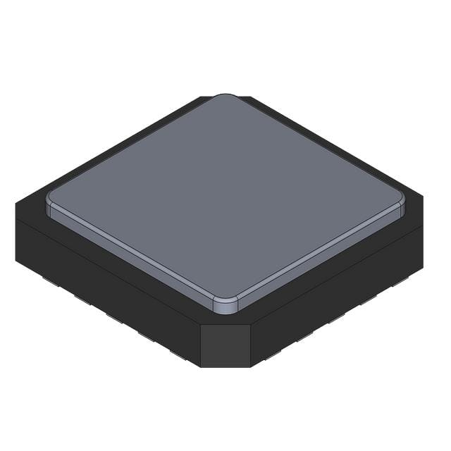
- Part No.:
- MAX7469UTP+
- Manufacturer:
- Analog Devices Inc./Maxim Integrated
- Category:
- Specialized
- Package:
- 20-WQFN Exposed Pad
- Datasheet:
-
 MAX7469UTP+.pdf
- Description:
- HDTV ANTI-ALIASING FILTER
- Quantity:
- Payment:

- Shipping:

Inventory:4,475
Please send an inquiry. Send us your inquiry, and we will respond immediately.
Product details
Overview
MAX7469UTP+ from Maxim Integrated is a triple-channel, I²C-programmable anti-aliasing filter and video buffer IC designed for analog video signal conditioning prior to ADC sampling in HD/SD television systems. It features 0dB gain, 5MHz–34MHz continuously adjustable cutoff (256 linear steps), ±0.6dB passband flatness (HD mode), 2VP-P output drive into 150Ω, and DC/AC-coupled outputs - deployed in LCD/PDP HDTV front-ends and set-top box video digitization paths.
For engineers reviewing the MAX7469UTP+ datasheet, MAX7469UTP+ pinout, MAX7469UTP+ application, or MAX7469UTP+ equivalent, key selection criteria include its software-tunable filter corner frequency, triple-channel sync-capable clamping, 20-pin TQFN-EP package with exposed pad, dual-supply operation (5V analog / 3.3V digital), and compatibility with Y Pb Pr, RGBHV, CVBS, and S-video formats.
Technical Context
The MAX7469UTP+ integrates three independent analog video channels, each with a digitally programmable 8th-order lowpass filter, clamp circuit, and unity-gain buffer. Its I²C interface controls filter cutoff (via 8-bit frequency register), clamp level (low/high per channel), sync source (internal/external), and bypass mode - enabling dynamic adaptation to 480i, 480p, 720p, 1080i, VGA–UXGA signals.
Each channel accepts AC-coupled inputs and delivers buffered outputs with <15ns group delay deviation (SD), <20ns (HD), and <0.25% differential gain error. The device uses internal sync detection on Channel 1 or external TTL-level sync on EXTSYNC pin, with programmable polarity, and supports both unipolar (Y/CVBS) and bipolar (Pb/Pr) clamp reference levels.
Key Specifications
| Parameter | Value and Actual Design Meaning |
|---|---|
| Filter Cutoff Range | 5MHz to 34MHz in 256 linear steps - enables precise Nyquist compliance for variable-resolution video inputs (e.g., 480p vs. 1080i). |
| Passband Flatness | ±0.6dB (HD: 100kHz–30MHz) - preserves luminance/chroma amplitude integrity across full HD bandwidth. |
| Output Drive | 2VP-P into 150Ω load - meets broadcast video line-driving requirements without external amplification. |
| Supply Voltages | +5V ±5% analog (AVDD), +2.7V to +3.6V digital (DVDD) - supports mixed-signal system partitioning with isolated noise domains. |
| Power-Down Current | 1.5mA typical - reduces system power during standby while retaining I²C accessibility for wake-up configuration. |
| Sync Flexibility | Supports sync-on-Y, sync-on-G, external positive/negative TTL sync, or sync-on-all-channels - accommodates diverse video source timing architectures. |
| Clamp Accuracy | ±100mV clamp level variation - ensures stable DC restoration for accurate blanking and sync-tip referencing in digitized video streams. |
Pinout & Package
Package: 20-pin TQFN-EP (5mm × 5mm, exposed pad), RoHS-compliant, thermal-enhanced for analog video signal integrity.
| Pin/Terminal | Circuit Role | Design Meaning |
|---|---|---|
| 1 (DGND) | Digital Ground Reference | Separate ground return for digital I²C interface - prevents digital switching noise from coupling into analog signal paths. |
| 2 (EXTSYNC) | External Sync Input | TTL-compatible input for horizontal sync when processing RGBHV or other sync-separate computer video formats. |
| 3 (SCL) | I²C Clock Input | Master-generated clock up to 400kHz - synchronizes all register writes/reads including filter frequency and clamp settings. |
| 4 (SDA) | I²C Data I/O | Open-drain bidirectional bus line - requires external pull-up; handles command byte (e.g., 0x12 for frequency register) and data payload. |
| 5 (DVDD) | Digital Supply | +2.7V to +3.6V supply for logic core and I²C interface - decoupled with 0.1µF capacitor to DGND for noise immunity. |
| 6, 8, 10 (OUT3/OUT2/OUT1) | Video Output Buffers | Unity-gain, rail-to-rail capable outputs - drive 150Ω loads directly; support DC coupling (no AC cap droop) or AC coupling. |
| 7, 9, 11 (AVDD) | Analog Supply | +4.75V to +5.25V supply for filters, clamps, and buffers - triple AVDD pins minimize IR drop and improve PSRR (>50dB). |
| 12–13 (A0, A1) | I²C Address Bits | Hardware-configurable LSBs of 7-bit slave address (10010xx) - allow up to four MAX7469UTP+ devices on same I²C bus. |
| 14, 15, 17, 19 (GND) | Analog Ground Planes | Multiple GND pins tied to solid ground plane - reduce ground impedance and maintain >62dB channel-to-channel isolation. |
| 16–18, 20 (IN1–IN3) | AC-Coupled Video Inputs | High-impedance inputs requiring 0.1µF series coupling caps - accept Y Pb Pr, CVBS, Y/C, or RGBHV with no level-shifting. |
| EP (Exposed Pad) | Thermal & Electrical Ground | Internally connected to GND - must be soldered to PCB ground plane for thermal dissipation and EMI suppression. |
Key Features
| Feature | Design Value |
|---|---|
| Continuously tunable anti-aliasing filter | 256-step I²C control from 5MHz to 34MHz - eliminates need for multiple fixed-filter BOM variants across SD/HD product lines. |
| Triple-channel sync-aware clamping | Per-channel clamp level selection (low for Y/CVBS, high for Pb/Pr) - maintains correct DC bias regardless of composite or component format. |
| Bypass mode with 100MHz bandwidth | Filter disabled via I²C command (0Eh) - preserves full signal path integrity for test modes or legacy non-filtered signal chains. |
| Low-distortion video buffering | <0.3% line-time and field-time distortion - enables direct connection to coaxial cables without AC-coupling capacitors, avoiding droop artifacts. |
| Dual-supply, low-power architecture | 5mW power-down mode with active I²C - allows fast wake-up (<650µs clamp settling) while minimizing idle power in always-on consumer devices. |
Applications
| HDTV Display Front-End | Set-Top Box Video Digitization |
|---|---|
|
Use Scenario: Analog video inputs (Y Pb Pr, RGBHV) from satellite/cable STB are conditioned before feeding an HDMI encoder or internal video processor. IC Role / Device Role / Timing Role: Anti-aliasing filter and DC-restored buffer - sets Nyquist-compliant bandwidth per input resolution and stabilizes blanking level for ADC sampling clock alignment. Use Value: Prevents aliasing artifacts in scaled 1080p output; eliminates need for external clamping diodes or precision op-amps in compact STB PCB layouts. |
Use Scenario: Legacy composite (CVBS) and S-video sources are digitized alongside HD component inputs in multi-format media hubs. IC Role / Device Role / Timing Role: Format-agnostic sync detector and triple-channel filter - extracts sync from any channel or external pin, then applies appropriate clamp and bandwidth limiting. Use Value: Single IC supports NTSC/PAL/HD standards without firmware reconfiguration; reduces BOM count versus discrete sync/clamp/filter solutions. |
| Personal Video Recorder (PVR) Tuner Board | Home Theater AV Receiver |
|
Use Scenario: Analog tuner outputs feed recording pipeline where signal fidelity and timing stability impact MPEG-2 encoding quality. IC Role / Device Role / Timing Role: Low-group-delay filter and noise-immune buffer - minimizes phase distortion across 480i–1080i range and rejects out-of-band RF interference pre-ADC. Use Value: Improves SNR by 69dB (100kHz–30MHz), reducing macroblocking in compressed recordings; 15ns group delay matching prevents color skew between channels. |
Use Scenario: Multi-source analog video switching matrix routes inputs (DVD, game console, camcorder) to scaler and display controller. IC Role / Device Role / Timing Role: Channel-isolated video conditioner - provides 62dB inter-channel isolation and independent filter tuning per source type (CVBS vs. RGBHV). Use Value: Eliminates crosstalk-induced ghosting during source switching; programmable bypass allows diagnostic loopback without hardware change. |
Equivalent & Alternatives
The following parts are listed as comparable options for similar video anti-aliasing filter applications.
| Alternative Part | Technical Difference | Application Difference | Selection Advice |
|---|---|---|---|
| MAX7470UTP+ | +6dB gain vs. MAX7469UTP+'s 0dB; identical filter range, pinout, and feature set | Preferred when driving back-matched 75Ω coaxial cables or ADCs requiring 2× voltage gain | Select MAX7470UTP+ only if system signal chain demands gain; otherwise MAX7469UTP+ avoids unnecessary amplification and noise. |
| AD8175ARUZ | Fixed 30MHz filter, no I²C control; triple-channel, 0dB gain, 20-TSSOP package | Suitable for cost-sensitive, static-resolution designs where dynamic filter adjustment is unnecessary | Choose AD8175ARUZ for simpler firmware and lower unit cost in fixed-HD-only products; MAX7469UTP+ required for multi-standard adaptability. |
Compared with MAX7470UTP+, the MAX7469UTP+ avoids gain-induced noise degradation in ADC-coupled systems; compared with AD8175ARUZ, it delivers field-upgradable bandwidth tuning and superior sync flexibility - critical for global broadcast equipment supporting NTSC/PAL/ATSC simultaneously.
Availability
MAX7469UTP+ is available at Aetrix Electronics and suitable for HDTV display front-ends, set-top box video digitization, and personal video recorder tuner boards requiring stable component supply, long-term lifecycle assurance, and traceable sourcing.
Supply support for MAX7469UTP+ includes scheduled delivery planning, volume procurement assistance, BOM continuity management, traceable sourcing, and lifecycle availability coordination for OEM customers, industrial embedded developers, connected-device designers, and electronics production programs.
Manufacturer
Maxim Integrated (now part of Analog Devices) is a semiconductor company specializing in high-performance analog, mixed-signal, and power-management ICs for industrial, communications, and consumer applications.
The MAX7469UTP+ belongs to Maxim's video signal conditioning product line, engineered specifically for high-fidelity analog video filtering and clamping in multi-standard broadcast and display systems - emphasizing programmability, low distortion, and thermal robustness.
FAQ
What is the maximum video resolution supported by the MAX7469UTP+?
The MAX7469UTP+ supports up to 1080i resolution through its programmable 34MHz filter cutoff and 100MHz bypass mode. Its electrical characteristics - including ±0.6dB passband flatness to 30MHz and <20ns group delay deviation - are validated for 1080i, 720p, 480p, and 480i scanning standards, as well as computer formats up to UXGA (1600×1200). The MAX7469UTP+ does not process digital video; it conditions analog baseband signals prior to ADC conversion.
Does the MAX7469UTP+ require external passive components for basic operation?
Yes, the MAX7469UTP+ requires external 0.1µF AC-coupling capacitors on all three inputs (IN1–IN3), 0.1µF bypass capacitors on AVDD and DVDD pins, and a 2.4kΩ or larger pull-up resistor on the SDA line. No external filter components are needed - the anti-aliasing filters are fully integrated. The exposed pad (EP) must be soldered to the PCB ground plane for thermal and electrical performance. These requirements are specified in the MAX7469UTP+ Typical Operating Circuit and Power-Supply Bypassing section.
Can the MAX7469UTP+ operate with only a +5V supply, or is the +3.3V digital supply mandatory?
The +3.3V digital supply (DVDD) is mandatory for the MAX7469UTP+. While AVDD operates from +4.75V to +5.25V for analog circuitry, DVDD must be within +2.7V to +3.6V to ensure correct I²C interface logic levels (VIH = 0.7×DVDD, VIL = 0.3×DVDD) and stable register operation. Using +5V on DVDD violates Absolute Maximum Ratings and risks communication failure or latch-up. The MAX7469UTP+ datasheet specifies separate analog and digital supplies to isolate noise - mixing them compromises PSRR and video SNR.
How does the MAX7469UTP+ handle sync detection for RGBHV inputs without embedded sync?
The MAX7469UTP+ uses the EXTSYNC pin to accept external TTL-level horizontal sync signals for RGBHV and other sync-separate formats. When configured via I²C command byte for external sync mode, the device detects positive- or negative-polarity sync pulses (programmable via register) and triggers clamping during the sync tip interval. This ensures accurate DC restoration even when sync is not embedded in the video waveform - a capability confirmed in the MAX7469UTP+ Sync Detector and Clamp Settings section and Electrical Characteristics table.
Is the MAX7469UTP+ pin-compatible with the MAX7470UTP+?
Yes, the MAX7469UTP+ is pin-compatible and footprint-compatible with the MAX7470UTP+. Both use the identical 20-pin TQFN-EP package (T2055-4), share identical pin functions, voltage ratings, and I²C register map - differing only in gain (0dB vs. +6dB) and default clamp level behavior. This allows direct substitution in existing layouts when gain requirements change, provided firmware adjusts for the different output amplitude and optional clamp settings. The MAX7469UTP+ and MAX7470UTP+ are explicitly listed as functionally matched variants in Maxim's Ordering Information table.
MAX7469UTP+ Specifications
- Product attributes
- Attribute value
- Manufacturer:
- Analog Devices Inc./Maxim Integrated
- Series:
- -
- Package/Case:
- 20-WQFN Exposed Pad
- Packaging:
- Bulk
- Product Status:
- Active
- Applications:
- HDTV, Recorders
- Interface:
- I2C, 2-Wire Serial
- Voltage - Supply:
- 2.7V ~ 3.6V, 4.75V ~ 5.25V
- Supplier Device Package:
- 20-TQFN (5x5)
- Grade:
- -
- Qualification:
- -
- Mounting Type:
- Surface Mount
MAX7469UTP+ FAQ
1.How can I place an order for MAX7469UTP+ through Aetrix?
Please submit a Request for Quotation (RFQ) for MAX7469UTP+ on Aetrix. Our sales agent will provide a competitive quotation and guide you through the order confirmation once you accept the terms.
2.Are the price and stock information for MAX7469UTP+ reliable?
The price and inventory of MAX7469UTP+ are updated periodically and may fluctuate due to market conditions. Stock and pricing data are typically refreshed every 24 hours. Quotation validity for MAX7469UTP+ is usually 5 days.
3.What payment methods are accepted for MAX7469UTP+?
We accept Wire Transfer, PayPal, Credit Card, Western Union, MoneyGram, and Escrow for MAX7469UTP+ transactions.
Note: Certain payment methods may incur a processing fee.
4.How is shipping managed for MAX7469UTP+?
MAX7469UTP+ orders can be shipped via leading logistics carriers, including DHL, UPS, FedEx, TNT, or Registered Mail.
Once your MAX7469UTP+ order is processed, you will receive an email with the shipment details and tracking number.
Note: Tracking information may take up to 24 hours to appear. Express delivery typically takes 3–5 business days.
5.How can I obtain technical support or documentation for MAX7469UTP+?
For technical support, including MAX7469UTP+ datasheets, pinout diagrams, or application guidance, please contact our engineering support team. They can provide detailed documentation and assistance for your MAX7469UTP+ requirements.
6.How does Aetrix verify that MAX7469UTP+ is sourced from the original manufacturer or authorized distributors?
All MAX7469UTP+ products on Aetrix are procured from qualified distributors and authorized channels. Our dedicated quality assurance team conducts strict verification, including traceability checks and, if necessary, third-party testing. This ensures that MAX7469UTP+ meets industry standards.
7.What is the process for return or replacement of MAX7469UTP+?
All MAX7469UTP+ units undergo pre-shipment inspection (PSI). If there is an issue with MAX7469UTP+, returns or replacements are accepted under the following conditions:
1.Quantity discrepancies, incorrect items, or visible external defects (such as breakage or corrosion), acknowledged by Aetrix.
2.The issue is reported within 90 days of delivery.
3.The MAX7469UTP+ part is unused and in its original packaging.
Return procedure for MAX7469UTP+:
1.Submit a request within 90 days.
2.Obtain a Return Material Authorization (RMA) from Aetrix.
MAX7469UTP+ Tags

-
NVT4857UKAZ
NXP Semiconductors

-
TCA8418RTWR
Texas Instruments

-
PCA9546APWR
Texas Instruments

-
MD0100N8-G
Microchip Technology

-
PCA9548APW,118
NXP Semiconductors

-
PCA9540BDP,118
NXP Semiconductors

-
PCA9548APWR
Texas Instruments

-
PCA9546APW,118
NXP Semiconductors

-
PTN3360DBS,518
NXP Semiconductors

-
PCA9546ABS,118
NXP Semiconductors

-
PCA9518PWR
Texas Instruments

-
PCA9545APW,118
NXP Semiconductors
Tech Hub

A practical engineering guide to 3.3V and 5V logic compatibility, input thresholds, resistor dividers, translator ICs, MOSFET level shifting, I2C pull-ups, timing limits and power-sequencing risks.

The 74HC595 uses push-pull logic outputs, while the TPIC6B595 uses 50 V open-drain DMOS sinks for higher-power loads. This guide compares timing, current limits, 3.3 V interfacing, load wiring, thermal…

The 74HC595 converts serial data into eight stable parallel outputs. This guide covers pin functions, shift and storage timing, OE and MR behavior, drive-current limits, cascading, voltage compatibilit…

A technical comparison of level-sensitive latches and edge-triggered flip-flops, covering timing windows, setup and hold limits, master–slave operation, time borrowing, race-through, HDL inference and…

A D latch stores one bit while Enable controls when data can pass. This reference covers gate-level operation, truth tables, transparency, setup and hold timing, LE versus OE, common ICs and practical …

An SR latch stores one bit through cross-coupled feedback. This engineering reference covers NOR and NAND implementations, truth tables, forbidden-state recovery, gated operation, switch debouncing, fa…

Latch circuits retain one bit through feedback. This technical reference covers SR and D latches, truth tables, transparency, timing limits, latch-versus-flip-flop behavior, applications and common log…

An engineering guide to LED driver operation, constant-current and constant-voltage outputs, linear and switching topologies, dimming, IC selection, calculations, replacement compatibility, and fault c…

Operational amplifier guide covering op amp basics, feedback, ideal vs real op amps, common configurations, buffer circuits, offset, bias current, gain-bandwidth, slew rate, rail-to-rail limits and sel…

Jumper cables guide covering safe connection order, red and black clamp placement, final ground connection, cable gauge, length, clamp quality, copper vs CCA cables, jump starter comparison and battery…


