
 My Inquiry
 My Account


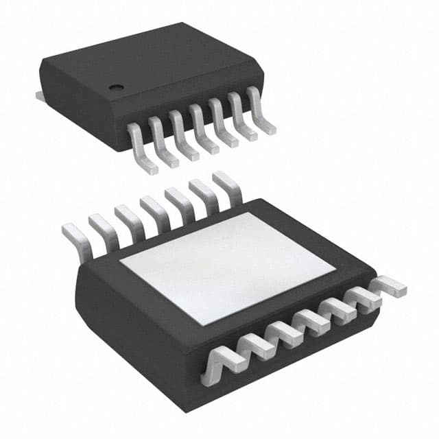
Analog Devices Inc./Maxim Integrated MAX8527EUD+T
- Part No.:
- MAX8527EUD+T
- Manufacturer:
- Analog Devices Inc./Maxim Integrated
- Package:
- 14-TSSOP (0.173", 4.40mm Width) Exposed Pad
- Datasheet:
-
 MAX8527EUD+T.pdf
- Description:
- IC REG LINEAR POS ADJ 2A 14TSSOP
- Quantity:
- Payment:

- Shipping:

Inventory:5,895
Please send an inquiry. Send us your inquiry, and we will respond immediately.
Product details
Overview
MAX8527EUD+T from Maxim Integrated is a 2A, low-dropout linear regulator with PMOS pass transistor, 1.425V–3.6V input range, 0.5V–(VIN−0.2V) adjustable output, ±1.4% accuracy over 0°C to +85°C, and integrated power-OK (POK) output. It delivers stable voltage regulation for high-current post-regulation in servers, optical modules, and base stations.
For engineers reviewing the MAX8527EUD+T datasheet, MAX8527EUD+T pinout, MAX8527EUD+T application, or MAX8527EUD+T equivalent, this page provides verified technical context, real-world transient response data (45mV deviation at 20mA→2A step), POK timing behavior (50µs fault delay), dropout specification (200mV @ 2A), and package-aware thermal design guidance for TSSOP-14 with exposed pad.
Technical Context
The MAX8527EUD+T uses an internal p-channel MOSFET pass device with 50mΩ typical on-resistance, enabling stable operation down to 1.425V input without base-drive current penalties. Its feedback loop references a precision 500mV FB threshold with ±1.4% total error across load, line, and temperature.
It integrates logic-controlled shutdown (EN pin), soft-start limiting inrush, short-circuit protection (4A current limit), and thermal shutdown (trip at +165°C, restart at +150°C). The open-drain POK output asserts high when VOUT is within ±10% of nominal and includes 50µs hysteresis delay to prevent chatter during marginal conditions.
Key Specifications
| Parameter | Value and Actual Design Meaning |
|---|---|
| Input Voltage Range | 1.425V to 3.6V - supports direct regulation from single-cell Li-ion or multi-rail intermediate supplies. |
| Output Current | 2A continuous - sufficient for FPGA core rails or ASIC I/O banks without external boost. |
| Dropout Voltage | 200mV @ 2A - enables high-efficiency regulation even at low VIN–VOUT headroom (e.g., 1.6V out from 1.8V input). |
| Output Accuracy | ±1.4% over 0°C to +85°C - ensures reliable margining for 1.2V/1.5V/1.8V digital rails under full thermal and load variation. |
| POK Threshold | ±10% of nominal VOUT - provides deterministic power-good signaling for sequenced system startup and fault detection. |
| Ground Current | 440µA typical operating / <50µA shutdown - minimizes standby power in always-on subsystems. |
| Capacitor Support | Compatible with 2.2µF ceramic input and 10µF ceramic output - eliminates need for tantalum or electrolytic capacitors, reducing board area and improving reliability. |
Pinout & Package
The MAX8527EUD+T is housed in a 14-pin TSSOP package (5mm × 6.4mm footprint, 1.1mm profile) with exposed thermal pad soldered to PCB ground for optimal power dissipation.
| Pin/Terminal | Circuit Role | Design Meaning |
|---|---|---|
| 1 EN | Enable control input | Active-high logic input; pull low for <50µA shutdown current; internal 10kΩ pulldown maintains OUT in high-impedance state. |
| 2–5 IN | Regulator input supply | Four parallel pins reduce IR drop and improve thermal path; requires ≥2.2µF ceramic bypass to GND. |
| 6, 7, 14 T.P. | Test pin | No functional connection in normal operation; left unconnected per datasheet. |
| 8 GND | Power and signal ground | Primary return path; connects internally to exposed pad for thermal conduction and low-impedance grounding. |
| 9 FB | Feedback reference node | Senses 500mV threshold; connects to resistor divider from OUT to set output voltage (VOUT = 0.5V × (1 + R1/R2)). |
| 10–13 OUT | Regulated output | Four parallel output pins handle 2A with minimal voltage drop; requires ≥10µF ceramic capacitor to GND for stability. |
| - POK | Power-OK open-drain output | Asserts high when VOUT is within ±10%; requires external pullup to IN; delays 50µs after threshold breach to reject noise. |
Key Features
| Feature | Design Value |
|---|---|
| p-Channel MOSFET Pass Device | Eliminates base-drive current loss; maintains 500µA quiescent current even in dropout or at full 2A load. |
| Fast Transient Response | 45mV max output deviation for 20mA→2A load step with only 10µF ceramic output capacitor - reduces need for bulk capacitance. |
| Integrated POK Output | Provides system-level power sequencing and fault monitoring without external comparators or timers. |
| Thermal & Short-Circuit Protection | Auto-recovering shutdown at +165°C junction temp and 4A current limit - prevents damage during sustained overload or PCB shorts. |
| Soft-Start Control | Internally limits inrush current during power-up; peak inrush calculable as IINRUSH ≈ ILOAD + (66 × COUT) µA - avoids input rail collapse. |
Applications
| Server Core Rails | Optical Module Bias |
|---|---|
Use Scenario: Regulating 1.2V core supply for high-speed SerDes PHYs in 1U rack servers with tight thermal constraints. IC Role / Device Role / Timing Role: Primary post-regulator delivering clean, low-noise 2A current with fast transient recovery to maintain signal integrity during burst traffic. Use Value: 200mV dropout enables use of 1.4V intermediate bus, reducing upstream converter losses by ~12% versus higher-VIN alternatives. | Use Scenario: Providing stable 3.3V bias to laser diode drivers and transimpedance amplifiers in SFP+ and QSFP modules. IC Role / Device Role / Timing Role: Low-noise, low-PSRR LDO ensuring minimal jitter injection into analog front-end circuitry. Use Value: 440µA quiescent current and ceramic capacitor compatibility enable compact, thermally efficient module designs meeting GR-468 reliability standards. |
| Base Station RF Front-End | Notebook GPU Core Supply |
Use Scenario: Powering RF power amplifier bias circuits in LTE/5G remote radio units where EMI sensitivity and thermal density are critical. IC Role / Device Role / Timing Role: High-accuracy, low-dropout regulator with POK signaling for safe PA enable sequencing and brownout detection. Use Value: ±1.4% output accuracy over temperature ensures consistent PA gain and linearity across −40°C to +85°C outdoor operating range. | Use Scenario: Delivering dynamic 0.8V–1.35V GPU core voltage in thin-and-light notebooks with aggressive thermal envelope. IC Role / Device Role / Timing Role: Adjustable LDO supporting DVFS via FB resistor network, with POK confirming valid rail before GPU clock enable. Use Value: Soft-start and 45mV transient deviation prevent display artifacts or GPU reset during rapid frequency scaling events. |
Equivalent & Alternatives
The following parts are listed as comparable options for similar LDO regulator applications.
| Alternative Part | Technical Difference | Application Difference | Selection Advice |
|---|---|---|---|
| TPS75225QPWPRQ1 | 2A, 250mV dropout @ 2A, automotive-grade (-40°C to +125°C), no POK output | Lacks integrated power-good signaling; requires external monitoring circuit for safety-critical systems | Choose when AEC-Q100 qualification is mandatory and POK is implemented separately. |
| LT3080IDDPBF | 1.1A, adjustable, 330mV dropout @ 1.1A, current-source architecture, no POK | Lower current rating and higher dropout; requires external sense resistor for current setting | Prefer for ultra-low-noise analog rails where 1.1A suffices and POK is not required. |
Compared with TPS75225QPWPRQ1 and LT3080IDDPBF, the MAX8527EUD+T uniquely combines 2A capability, 200mV dropout, ±1.4% accuracy, and integrated POK in a single TSSOP-14 package - making it optimal for space-constrained, high-reliability digital systems requiring autonomous power-status reporting.
Availability
MAX8527EUD+T is available at Aetrix Electronics and suitable for server power delivery, optical transceiver biasing, and base station RF front-end applications requiring stable component supply, long-term lifecycle support, and RoHS-compliant packaging.
Supply support for MAX8527EUD+T includes scheduled delivery planning, volume procurement assistance, BOM continuity management, traceable sourcing, and lifecycle availability coordination for OEM customers, industrial embedded developers, connected-device designers, and electronics production programs.
Manufacturer
Maxim Integrated (now part of Analog Devices) is a U.S.-based semiconductor company specializing in high-performance analog, mixed-signal, and power management ICs for demanding industrial, communications, and computing applications.
The MAX8527EUD+T belongs to Maxim's high-current LDO family designed specifically for post-regulation in dense, thermally constrained systems where low dropout, fast transient response, and integrated status signaling are essential.
FAQ
What is the minimum input voltage required for stable operation of the MAX8527EUD+T?
The MAX8527EUD+T operates stably down to 1.425V input voltage, as specified in its absolute maximum ratings and electrical characteristics. Below this threshold, undervoltage lockout activates at 1.35V (typical), disabling regulation. This allows direct use with single-cell Li-ion batteries or low-voltage intermediate buses while maintaining ±1.4% output accuracy across temperature and load.
Does the MAX8527EUD+T require external components for basic operation?
Yes - the MAX8527EUD+T requires at minimum a 2.2µF ceramic capacitor between IN and GND, a 10µF ceramic capacitor between OUT and GND, two resistors for FB-based output voltage setting, and a pullup resistor on the POK pin. These are mandatory for stability, accuracy, and proper POK functionality; omitting any compromises regulation performance or fault reporting.
How does the POK output of the MAX8527EUD+T behave during startup and fault conditions?
The POK output of the MAX8527EUD+T remains low until VOUT reaches within ±10% of its nominal value, then transitions high with a 50µs delay to reject noise. During shutdown (EN = low), POK is forced low. If VOUT drifts outside tolerance due to overload or thermal fault, POK transitions low after the same 50µs delay - providing deterministic, glitch-immune power-status signaling for system controllers.
Can the MAX8527EUD+T be used with output voltages below 1.0V?
Yes - the MAX8527EUD+T supports output voltages as low as 0.5V using the FB pin and external resistor divider. Its 500mV feedback reference and ±1.4% accuracy ensure reliable regulation at sub-1V levels, making it suitable for modern low-voltage FPGA and ASIC core rails. Layout must minimize FB trace impedance to preserve accuracy.
What thermal considerations apply to the MAX8527EUD+T in a 2A application?
In a 2A application, the MAX8527EUD+T dissipates up to (VIN − VOUT) × 2A. With its TSSOP-14 package and exposed thermal pad, thermal resistance θJA is ~48°C/W when properly soldered to a 1-in² copper pad. To hold junction temperature ≤+150°C, ambient must stay ≤+70°C for a 0.2V dropout case - requiring adequate airflow or heatsinking in enclosed environments.
MAX8527EUD+T Specifications
- Product attributes
- Attribute value
- Manufacturer:
- Analog Devices Inc./Maxim Integrated
- Series:
- -
- Package/Case:
- 14-TSSOP (0.173", 4.40mm Width) Exposed Pad
- Packaging:
- Tape & Reel (TR)
- Product Status:
- Active
- Output Configuration:
- Positive
- Output Type:
- Adjustable
- Number of Regulators:
- 1
- Voltage - Input (Max):
- 3.6V
- Voltage - Output (Min/Fixed):
- 0.5V
- Voltage - Output (Max):
- 3.4V
- Voltage Dropout (Max):
- 0.2V @ 2A
- Current - Output:
- 2A
- Current - Quiescent (Iq):
- 440 µA
- Current - Supply (Max):
- -
- PSRR:
- -
- Control Features:
- Enable, Power Good
- Protection Features:
- Over Temperature, Short Circuit
- Operating Temperature:
- -40°C ~ 85°C
- Grade:
- -
- Qualification:
- -
- Mounting Type:
- Surface Mount
- Supplier Device Package:
- 14-TSSOP-EP
MAX8527EUD+T FAQ
1.How can I place an order for MAX8527EUD+T through Aetrix?
Please submit a Request for Quotation (RFQ) for MAX8527EUD+T on Aetrix. Our sales agent will provide a competitive quotation and guide you through the order confirmation once you accept the terms.
2.Are the price and stock information for MAX8527EUD+T reliable?
The price and inventory of MAX8527EUD+T are updated periodically and may fluctuate due to market conditions. Stock and pricing data are typically refreshed every 24 hours. Quotation validity for MAX8527EUD+T is usually 5 days.
3.What payment methods are accepted for MAX8527EUD+T?
We accept Wire Transfer, PayPal, Credit Card, Western Union, MoneyGram, and Escrow for MAX8527EUD+T transactions.
Note: Certain payment methods may incur a processing fee.
4.How is shipping managed for MAX8527EUD+T?
MAX8527EUD+T orders can be shipped via leading logistics carriers, including DHL, UPS, FedEx, TNT, or Registered Mail.
Once your MAX8527EUD+T order is processed, you will receive an email with the shipment details and tracking number.
Note: Tracking information may take up to 24 hours to appear. Express delivery typically takes 3–5 business days.
5.How can I obtain technical support or documentation for MAX8527EUD+T?
For technical support, including MAX8527EUD+T datasheets, pinout diagrams, or application guidance, please contact our engineering support team. They can provide detailed documentation and assistance for your MAX8527EUD+T requirements.
6.How does Aetrix verify that MAX8527EUD+T is sourced from the original manufacturer or authorized distributors?
All MAX8527EUD+T products on Aetrix are procured from qualified distributors and authorized channels. Our dedicated quality assurance team conducts strict verification, including traceability checks and, if necessary, third-party testing. This ensures that MAX8527EUD+T meets industry standards.
7.What is the process for return or replacement of MAX8527EUD+T?
All MAX8527EUD+T units undergo pre-shipment inspection (PSI). If there is an issue with MAX8527EUD+T, returns or replacements are accepted under the following conditions:
1.Quantity discrepancies, incorrect items, or visible external defects (such as breakage or corrosion), acknowledged by Aetrix.
2.The issue is reported within 90 days of delivery.
3.The MAX8527EUD+T part is unused and in its original packaging.
Return procedure for MAX8527EUD+T:
1.Submit a request within 90 days.
2.Obtain a Return Material Authorization (RMA) from Aetrix.
MAX8527EUD+T Tags

-
MIC5504-1.8YM5-TR
Microchip Technology
-
MIC5504-3.3YM5-TR
Microchip Technology

-
MIC5365-3.0YC5-TR
Microchip Technology
-
MIC5365-1.8YC5-TR
Microchip Technology
-
MIC5365-2.5YC5-TR
Microchip Technology
-
MIC5365-3.3YC5-TR
Microchip Technology

-
MIC5365-3.3YD5-TR
Microchip Technology

-
MIC5317-3.3YM5-TR
Microchip Technology

-
TLV1117LV33DCYR
Texas Instruments

-
MIC5317-3.3YMT-TZ
Microchip Technology

-
MIC5528-3.3YMT-TR
Microchip Technology

-
TLV75801PDRVR
Texas Instruments
Tech Hub

An SR latch stores one bit through cross-coupled feedback. This engineering reference covers NOR and NAND implementations, truth tables, forbidden-state recovery, gated operation, switch debouncing, fa…

Latch circuits retain one bit through feedback. This technical reference covers SR and D latches, truth tables, transparency, timing limits, latch-versus-flip-flop behavior, applications and common log…

An engineering guide to LED driver operation, constant-current and constant-voltage outputs, linear and switching topologies, dimming, IC selection, calculations, replacement compatibility, and fault c…

Operational amplifier guide covering op amp basics, feedback, ideal vs real op amps, common configurations, buffer circuits, offset, bias current, gain-bandwidth, slew rate, rail-to-rail limits and sel…

Jumper cables guide covering safe connection order, red and black clamp placement, final ground connection, cable gauge, length, clamp quality, copper vs CCA cables, jump starter comparison and battery…

LDO regulator guide covering low dropout voltage, power dissipation, thermal design, PSRR, output noise, capacitor stability, adjustable LDO circuits, LDO vs buck converter and datasheet selection chec…

Conditional Access Module guide covering CAM meaning, CI/CI+ interface, smart card authorization, DVB security workflow, TV and set-top box compatibility, internal electronics, ESD protection, connecto…

Guide to electronic component obsolescence covering EOL risk, PCN/PDN notices, last-time buy planning, replacement options, form-fit-function validation, counterfeit risk and BOM lifecycle management.

18650 battery guide covering lithium-ion cell basics, 3.6V/3.7V voltage, 4.2V charging, mAh and Wh capacity, protected cells, chargers, BMS, series-parallel packs, holders, welding and sourcing checks.…

Hall effect sensor guide covering working principle, linear and digital sensors, Arduino circuits, current sensing, speed detection, automotive applications, A3144 examples, signal filtering and datash…


