
 My Inquiry
 My Account


Analog Devices Inc./Maxim Integrated MAX861ESA+
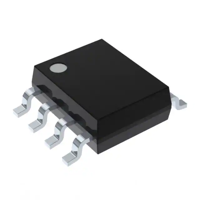
- Part No.:
- MAX861ESA+
- Manufacturer:
- Analog Devices Inc./Maxim Integrated
- Package:
- 8-SOIC (0.154", 3.90mm Width)
- Datasheet:
-
 MAX861ESA+.pdf
- Description:
- IC REG CHARG PUMP INV 50MA 8SOIC
- Quantity:
- Payment:

- Shipping:

Inventory:805
Please send an inquiry. Send us your inquiry, and we will respond immediately.
Product details
Overview
MAX861ESA+ from Maxim Integrated is a frequency-selectable, 50mA switched-capacitor voltage converter that inverts +1.5V to +5.5V inputs or doubles +2.5V to +5.5V inputs. It operates at three user-selectable switching frequencies (13/100/250 kHz), delivers 87% efficiency at 50mA load, and features 12Ω output resistance and 1µA shutdown current. It serves as a compact, inductorless power supply for portable medical instruments and handheld test equipment.
For engineers reviewing the MAX861ESA+ datasheet, MAX861ESA+ pinout, MAX861ESA+ application, or MAX861ESA+ equivalent, key selection criteria include its -40°C to +85°C operating range, SO-8 package compatibility, inverter/doubler mode flexibility via LV pin, and trade-offs between capacitor size, quiescent current, and EMI sensitivity across its three FC-selectable frequencies.
Technical Context
The MAX861ESA+ implements a BiCMOS charge-pump architecture with direct oscillator-to-switch coupling (no frequency division), enabling precise control of switching frequency via the FC pin. Its internal switch resistance (~8Ω) combines with external capacitor ESR to determine total output resistance (typically 12Ω with 0.2Ω ESR caps).
Operation supports two distinct configurations: inverter mode (LV = GND) delivering –VIN output, and doubler mode (LV = OUT) delivering +2VIN output. Shutdown is active-low on the SHDN pin, reducing supply current to <1µA while preserving stateless operation-no sequencing or biasing required for wake-up.
Key Specifications
| Parameter | Value and Actual Design Meaning |
|---|---|
| Output Current | 50mA maximum continuous - supports rail-splitting and op-amp dual supplies without inductors. |
| Switching Frequencies | 13/100/250 kHz - selectable via FC pin to optimize capacitor size, EMI, and quiescent current. |
| Efficiency | 87% at 50mA load - enables battery-powered operation with minimal thermal impact. |
| Output Resistance | 12Ω typical - determines output voltage droop: ~0.6V drop at 50mA from ideal –VIN. |
| Shutdown Current | <1µA - extends battery life in sleep-mode portable instrumentation. |
| Operating Temperature | –40°C to +85°C - qualified for industrial and medical-grade embedded systems. |
| Supply Voltage Range | +1.5V to +5.5V (inverter), +2.5V to +5.5V (doubler) - compatible with single-cell Li-ion, alkaline, and logic rails. |
Pinout & Package
MAX861ESA+ is housed in an 8-pin SO (Small Outline) package per outline S8-4, RoHS-compliant, with 1.27mm pitch and standard JEDEC MS-012AC footprint.
| Pin/Terminal | Circuit Role | Design Meaning |
|---|---|---|
| FC (Pin 1) | Frequency Control input | Selects switching frequency: FC = VDD → 13kHz, FC = GND → 100kHz, FC = OUT → 250kHz. |
| C1+ (Pin 2) | Flying capacitor positive terminal | Connects to one side of flying capacitor C1; internal switch node during charge phase. |
| GND (Pin 3) | Ground reference | Primary return path for all internal circuitry and external capacitors. |
| C1− (Pin 4) | Flying capacitor negative terminal | Connects to other side of flying capacitor C1; alternates polarity with C1+ during pump cycle. |
| OUT (Pin 5) | Inverted or doubled output | Delivers –VIN (inverter) or +2VIN (doubler); output impedance dominates voltage regulation. |
| LV (Pin 6) | Mode selection input | LV = GND → inverter; LV = OUT → doubler; floating allowed only above 3V in inverter mode. |
| SHDN (Pin 7) | Active-low shutdown control | Pull low to disable charge pump; draws <1µA; pull high to enable. |
| VDD (Pin 8) | Positive input supply | Accepts +1.5V to +5.5V (inverter) or +2.5V to +5.5V (doubler); powers internal oscillator and switches. |
Key Features
| Feature | Design Value |
|---|---|
| Inverter or doubler configuration | Single device supports both topologies via LV pin connection-no BOM change needed for dual-voltage design. |
| Three-frequency selection | Enables EMI-sensitive designs to avoid critical bands (e.g., 100kHz avoids audio band; 250kHz minimizes cap size). |
| 12Ω output resistance | Provides predictable load regulation: e.g., –5.0V no-load drops to –4.4V at 50mA, simplifying system-level tolerance analysis. |
| 1µA shutdown current | Allows integration into always-on systems where microcontroller-controlled power gating is required. |
| SO-8 package compatibility | Direct replacement for legacy ICL7660/MAX660 footprints with minimal board rework (SHDN replaces OSC). |
Applications
| Portable Medical Instruments | Hand-Held Test Equipment |
|---|---|
Use Scenario: Powering analog front-end circuits (e.g., ADC drivers, sensor signal conditioners) in battery-operated blood glucose meters or pulse oximeters. IC Role / Device Role / Timing Role: Generates clean –3.3V rail from +3.3V main supply to bias op-amps and reference buffers in precision measurement paths. Use Value: Eliminates magnetic components, reducing EMI that could corrupt low-level bio-signal acquisition. | Use Scenario: Providing dual ±5V supplies for analog comparators and display drivers in handheld multimeters or oscilloscope probes. IC Role / Device Role / Timing Role: Functions as inverter to generate –5V from +5V USB-derived rail, supporting rail-to-rail input stages and LCD bias. Use Value: Enables compact form factor by replacing discrete inductor-based DC/DC converters with two 10µF ceramic caps. |
| Operational-Amplifier Power Supplies | Interface Power Supplies |
Use Scenario: Supplying split rails to low-noise op-amps in portable audio codecs or instrumentation amplifiers. IC Role / Device Role / Timing Role: Delivers –2.5V from +2.5V logic supply to enable true bipolar signal handling in single-supply systems. Use Value: Maintains PSRR >60dB up to 100kHz due to high switching frequency, minimizing noise coupling into sensitive analog nodes. | Use Scenario: Generating isolated auxiliary voltages for RS-232 transceivers or CAN bus interface ICs in industrial handheld terminals. IC Role / Device Role / Timing Role: Doubles +3.3V MCU rail to +6.6V for RS-232 driver compliance, using LV = OUT configuration. Use Value: Avoids need for external boost converter while meeting TIA-232 voltage swing requirements under varying load. |
Equivalent & Alternatives
The following parts are listed as comparable options for similar switched-capacitor voltage converter applications.
| Alternative Part | Technical Difference | Application Difference | Selection Advice |
|---|---|---|---|
| MAX860ESA+ | Different FC frequency set: 6/50/130 kHz vs. MAX861ESA+'s 13/100/250 kHz; otherwise identical pinout, specs, and package. | Better suited for ultra-low-quiescent-current designs where 6kHz minimizes switching loss, but less optimal for EMI-sensitive 100kHz+ bands. | Select MAX860ESA+ when lowest possible no-load current is critical; choose MAX861ESA+ when higher base frequency improves capacitor sizing or noise avoidance. |
| MAX660CPA+ | Higher 100mA output, lower 6.5Ω output resistance, fixed 5/40kHz switching; requires OSC pin tie-off instead of SHDN. | Supports heavier loads (e.g., multiple op-amps), but larger output droop at low frequencies limits dynamic response in fast-slewing circuits. | Use MAX660CPA+ when >50mA output or tighter regulation is required; MAX861ESA+ preferred for space-constrained, low-EMI, or battery-critical designs. |
Compared with MAX860ESA+, MAX861ESA+ offers higher base switching frequencies for smaller capacitors and better EMI management, while MAX660CPA+ provides greater output current and lower output resistance at the cost of fixed frequency and larger solution size.
Availability
MAX861ESA+ is available at Aetrix Electronics and suitable for portable medical instruments, hand-held test equipment, operational-amplifier power supplies, and interface power supplies requiring stable component supply across extended temperature ranges.
Supply support for MAX861ESA+ includes scheduled delivery planning, volume procurement assistance, BOM continuity management, traceable sourcing, and lifecycle availability coordination for OEM customers, industrial embedded developers, connected-device designers, and electronics production programs.
Manufacturer
Maxim Integrated (now part of Analog Devices) is a U.S.-based semiconductor company specializing in high-performance analog, mixed-signal, and power-management ICs for industrial, medical, and communications applications.
The MAX860/MAX861 product line was designed specifically to replace legacy charge pumps like the ICL7660 with higher efficiency, wider input range, and flexible frequency control-targeting space- and power-constrained portable electronics.
FAQ
What are the valid switching frequencies for MAX861ESA+ and how are they selected?
The MAX861ESA+ supports three nominal switching frequencies: 13kHz (FC = VDD), 100kHz (FC = GND), and 250kHz (FC = OUT). These values are confirmed in Table 1 of the datasheet and apply specifically to the MAX861 variant. Selection is made by hard-wiring the FC pin to the appropriate voltage node-no external clock or configuration register is involved. Each frequency directly impacts capacitor sizing, quiescent current, and EMI profile.
Can MAX861ESA+ be used as a voltage doubler, and what is required to configure it?
Yes, MAX861ESA+ can operate as a positive voltage doubler. To configure it, connect the LV pin to the OUT pin (not GND). In this mode, the device accepts +2.5V to +5.5V input and delivers approximately +2×VIN at the OUT pin. The electrical characteristics-including output current, efficiency, and frequency behavior-remain consistent with inverter mode except for the expanded input voltage range and slightly higher no-load supply current.
What is the output resistance of MAX861ESA+ and how does it affect load regulation?
The MAX861ESA+ has a typical output resistance of 12Ω, as specified in the Electrical Characteristics table under "Output Resistance" (ROUT). This value includes internal switch resistance (~8Ω) and contributions from external capacitor ESR. At 50mA load, this results in ~0.6V output droop from the ideal inverted or doubled voltage-e.g., –5.0V becomes –4.4V. Designers must account for this linear drop when specifying output voltage tolerances.
Is MAX861ESA+ pin-compatible with the ICL7660 or MAX660, and what modifications are needed?
MAX861ESA+ is footprint-compatible with the ICL7660 and MAX660 in SO-8 packages, but pin functions differ: Pin 7 is SHDN (not OSC), and Pin 6 is LV (not NC). To retrofit, tie SHDN to VDD (not float), and connect LV to GND (inverter) or OUT (doubler). FC (Pin 1) may remain unconnected (defaults to 13kHz) or be wired to select frequency-no changes needed for basic operation.
What is the minimum input voltage required for MAX861ESA+ in inverter mode?
The minimum input voltage for MAX861ESA+ in inverter mode is +1.5V, as explicitly stated in the General Description and Electrical Characteristics tables. Operation below this voltage is not guaranteed and may result in failure to start or unstable output. This 1.5V lower limit enables use with single-cell alkaline or NiMH batteries, distinguishing it from the MAX660 (2.0V min) and ICL7660 (1.5V min but only 10mA output).
MAX861ESA+ Specifications
- Product attributes
- Attribute value
- Manufacturer:
- Analog Devices Inc./Maxim Integrated
- Series:
- -
- Package/Case:
- 8-SOIC (0.154", 3.90mm Width)
- Packaging:
- Tube
- Product Status:
- Active
- Function:
- Ratiometric
- Output Configuration:
- Positive or Negative
- Topology:
- Charge Pump
- Output Type:
- Fixed
- Number of Outputs:
- 1
- Voltage - Input (Min):
- 1.5V, 2.5V
- Voltage - Input (Max):
- 5.5V
- Voltage - Output (Min/Fixed):
- -Vin, 2Vin
- Voltage - Output (Max):
- -
- Current - Output:
- 50mA
- Frequency - Switching:
- 13kHz, 100kHz, 250kHz
- Synchronous Rectifier:
- No
- Operating Temperature:
- -40°C ~ 85°C (TA)
- Grade:
- -
- Qualification:
- -
- Mounting Type:
- Surface Mount
- Supplier Device Package:
- 8-SOIC
MAX861ESA+ FAQ
1.How can I place an order for MAX861ESA+ through Aetrix?
Please submit a Request for Quotation (RFQ) for MAX861ESA+ on Aetrix. Our sales agent will provide a competitive quotation and guide you through the order confirmation once you accept the terms.
2.Are the price and stock information for MAX861ESA+ reliable?
The price and inventory of MAX861ESA+ are updated periodically and may fluctuate due to market conditions. Stock and pricing data are typically refreshed every 24 hours. Quotation validity for MAX861ESA+ is usually 5 days.
3.What payment methods are accepted for MAX861ESA+?
We accept Wire Transfer, PayPal, Credit Card, Western Union, MoneyGram, and Escrow for MAX861ESA+ transactions.
Note: Certain payment methods may incur a processing fee.
4.How is shipping managed for MAX861ESA+?
MAX861ESA+ orders can be shipped via leading logistics carriers, including DHL, UPS, FedEx, TNT, or Registered Mail.
Once your MAX861ESA+ order is processed, you will receive an email with the shipment details and tracking number.
Note: Tracking information may take up to 24 hours to appear. Express delivery typically takes 3–5 business days.
5.How can I obtain technical support or documentation for MAX861ESA+?
For technical support, including MAX861ESA+ datasheets, pinout diagrams, or application guidance, please contact our engineering support team. They can provide detailed documentation and assistance for your MAX861ESA+ requirements.
6.How does Aetrix verify that MAX861ESA+ is sourced from the original manufacturer or authorized distributors?
All MAX861ESA+ products on Aetrix are procured from qualified distributors and authorized channels. Our dedicated quality assurance team conducts strict verification, including traceability checks and, if necessary, third-party testing. This ensures that MAX861ESA+ meets industry standards.
7.What is the process for return or replacement of MAX861ESA+?
All MAX861ESA+ units undergo pre-shipment inspection (PSI). If there is an issue with MAX861ESA+, returns or replacements are accepted under the following conditions:
1.Quantity discrepancies, incorrect items, or visible external defects (such as breakage or corrosion), acknowledged by Aetrix.
2.The issue is reported within 90 days of delivery.
3.The MAX861ESA+ part is unused and in its original packaging.
Return procedure for MAX861ESA+:
1.Submit a request within 90 days.
2.Obtain a Return Material Authorization (RMA) from Aetrix.
MAX861ESA+ Tags
-
TPS562201DDCR
Texas Instruments

-
MC34063ABD-TR
STMicroelectronics
-
TPS561201DDCR
Texas Instruments

-
MC33063ADR
Texas Instruments
-
MC34063ADR
Texas Instruments

-
TPS560200DBVR
Texas Instruments
-
AP3012KTR-G1
Diodes Incorporated
-
TLV61048DBVR
Texas Instruments
-
AZ34063UMTR-G1
Diodes Incorporated
-
TPS562200DDCR
Texas Instruments
-
AP62300TWU-7
Diodes Incorporated
-
MC34063EBD-TR
STMicroelectronics
Tech Hub

A practical engineering guide to 3.3V and 5V logic compatibility, input thresholds, resistor dividers, translator ICs, MOSFET level shifting, I2C pull-ups, timing limits and power-sequencing risks.

The 74HC595 uses push-pull logic outputs, while the TPIC6B595 uses 50 V open-drain DMOS sinks for higher-power loads. This guide compares timing, current limits, 3.3 V interfacing, load wiring, thermal…

The 74HC595 converts serial data into eight stable parallel outputs. This guide covers pin functions, shift and storage timing, OE and MR behavior, drive-current limits, cascading, voltage compatibilit…

A technical comparison of level-sensitive latches and edge-triggered flip-flops, covering timing windows, setup and hold limits, master–slave operation, time borrowing, race-through, HDL inference and…

A D latch stores one bit while Enable controls when data can pass. This reference covers gate-level operation, truth tables, transparency, setup and hold timing, LE versus OE, common ICs and practical …

An SR latch stores one bit through cross-coupled feedback. This engineering reference covers NOR and NAND implementations, truth tables, forbidden-state recovery, gated operation, switch debouncing, fa…

Latch circuits retain one bit through feedback. This technical reference covers SR and D latches, truth tables, transparency, timing limits, latch-versus-flip-flop behavior, applications and common log…

An engineering guide to LED driver operation, constant-current and constant-voltage outputs, linear and switching topologies, dimming, IC selection, calculations, replacement compatibility, and fault c…

Operational amplifier guide covering op amp basics, feedback, ideal vs real op amps, common configurations, buffer circuits, offset, bias current, gain-bandwidth, slew rate, rail-to-rail limits and sel…

Jumper cables guide covering safe connection order, red and black clamp placement, final ground connection, cable gauge, length, clamp quality, copper vs CCA cables, jump starter comparison and battery…


