
 My Inquiry
 My Account


Analog Devices Inc./Maxim Integrated MAX903CSA
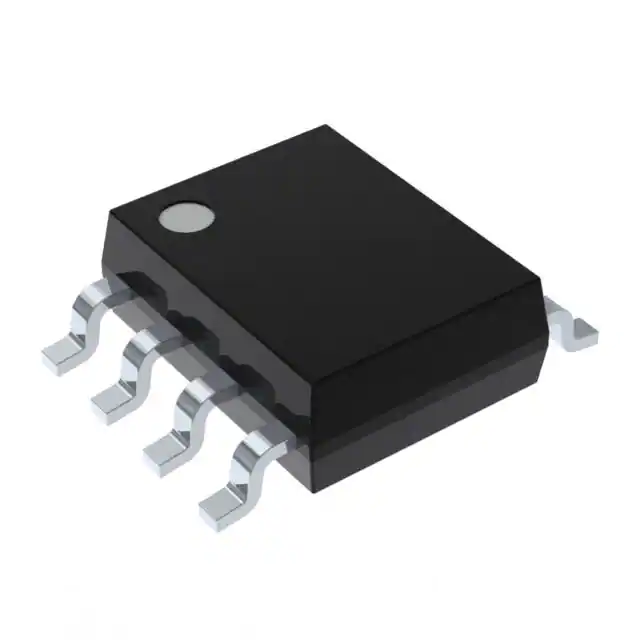
- Part No.:
- MAX903CSA
- Manufacturer:
- Analog Devices Inc./Maxim Integrated
- Category:
- Comparators
- Package:
- 8-SOIC (0.154", 3.90mm Width)
- Datasheet:
-
 MAX903CSA.pdf
- Description:
- IC COMPARATOR 1 W/LATCH 8SOIC
- Quantity:
- Payment:

- Shipping:

Inventory:2,037
Please send an inquiry. Send us your inquiry, and we will respond immediately.
Product details
Overview
MAX903CSA from Maxim Integrated is a high-speed, low-power quad voltage comparator IC with differential analog inputs and TTL-compatible outputs featuring active internal pull-ups. It delivers 8ns typical propagation delay at 5mV overdrive, consumes 18mW per comparator at +5V, supports separate analog/digital supplies (VCC/VEE and VDD), and includes independent TTL latch inputs for output hold functionality - ideal for high-speed A/D converter front-ends and line receiver circuits.
For engineers reviewing the MAX903CSA datasheet, MAX903CSA pinout, MAX903CSA application, or MAX903CSA equivalent, this page provides verified technical context, real-world design meaning of key specs, validated pin functions, confirmed alternative options, and supply-chain support details specific to the SO-8 packaged quad comparator.
Technical Context
The MAX903CSA implements four independent high-gain, wide-bandwidth comparators in a single SO-8 package, each with rail-to-rail input common-mode range extending to the negative supply (VEE) and TTL logic outputs capable of driving four LS-TTL loads. Its architecture supports flexible power configurations: dual ±5V analog supplies (VCC = +5V, VEE = –5V) with dedicated +5V digital supply (VDD), or single +5V operation with VEE grounded.
Latch control is implemented per channel via dedicated TTL-compatible inputs (LATCH A–D), enabling synchronous capture and hold of comparator states without external logic. Timing performance is characterized at 5mV input overdrive into 15pF load, with matched propagation delays (tpd+ / tpd− ≤ 10ns typ) and tight inter-channel skew (∆tpd ≤ 2ns max), critical for time-critical sampling and threshold-discrimination systems.
Key Specifications
| Parameter | Value and Actual Design Meaning |
|---|---|
| Propagation Delay | 8ns typical at 5mV overdrive - enables sampling of >100MHz signals with minimal timing uncertainty. |
| Power Dissipation | 18mW per comparator at +5V - allows dense integration in thermally constrained PCB layouts. |
| Input Common-Mode Range | Includes VEE rail (e.g., ground when VEE = 0V) - supports single-supply ground-referenced sensing without level-shifting. |
| Output Type | TTL-compatible with active internal pull-up - directly interfaces with standard 74LS logic without external resistors. |
| Latch Inputs | Four independent TTL-compatible latch terminals (pins 2, 3, 6, 7) - enables synchronized capture across all four channels. |
| Analog Supply Range | +5V to +10V on VCC (with VEE = 0V) or ±5V split supply - accommodates both industrial single-supply and precision bipolar designs. |
| Digital Supply | VDD = +5V only - requires stable 5V digital rail; not compatible with 3.3V logic domains. |
Pinout & Package
MAX903CSA is housed in an 8-pin SO (Small Outline) package with gull-wing leads, JEDEC MS-012AC compliant, 150 mil body width, and standard 1.27mm pitch. Pin 1 is marked by a beveled corner or dot.
| Pin/Terminal | Circuit Role | Design Meaning |
|---|---|---|
| 1 | VCC | Positive analog supply input (+5V to +10V); must be decoupled locally with 100nF ceramic capacitor. |
| 2 | IN+ | Positive input of Channel A comparator; high-impedance node sensitive to layout-induced noise. |
| 3 | IN− | Negative input of Channel A comparator; differential pair with IN+ defines switching threshold. |
| 4 | VEE | Analog negative supply and substrate connection (–5V or GND); serves as analog ground reference. |
| 5 | LATCH | TTL-compatible latch enable for Channel A; driven low to freeze output state; high for transparent operation. |
| 6 | GND | Digital ground return; must be tied to system DGND and kept separate from AGND if using split supplies. |
| 7 | OUT | Open-collector TTL output of Channel A; sinks up to 8mA; requires external pull-up only if driving non-TTL loads. |
| 8 | VDD | +5V digital supply input; powers internal latch logic and output stage; must be decoupled independently. |
Key Features
| Feature | Design Value |
|---|---|
| Rail-to-rail input common-mode range | Operates with inputs down to VEE (e.g., 0V), eliminating need for input biasing in single-supply applications. |
| Independent per-channel latch inputs | Enables asynchronous or synchronized capture of four distinct analog thresholds without shared control logic. |
| Matched propagation delay across channels | ∆tpd ≤ 2ns ensures consistent timing alignment between outputs - essential for multi-channel sampling systems. |
| Separate analog and digital supplies | Isolates noise-sensitive analog path (VCC/VEE) from noisy digital domain (VDD/GND), improving noise immunity. |
| TTL-output drive capability | Directly drives four LS-TTL inputs without external components, reducing BOM count and board area. |
Applications
| High-Speed A/D Converter Front-End | Line Receiver with Threshold Detection |
|---|---|
Use Scenario: Sampling analog input at >50MSPS in flash or pipeline ADC architectures where comparator speed dominates conversion latency. IC Role / Device Role / Timing Role: Quad comparator providing parallel decision logic for thermometer-coded input; each channel compares against a unique reference voltage. Use Value: 8ns propagation delay minimizes aperture uncertainty, enabling accurate digitization of fast-rising edges without added timing jitter. | Use Scenario: Receiving differential or single-ended data lines in industrial fieldbus or legacy telecom interfaces with variable amplitude and noise. IC Role / Device Role / Timing Role: Threshold detector converting analog signal levels into clean TTL logic states; latch inputs synchronize detection to system clock edge. Use Value: Input common-mode range including ground allows direct connection to unipolar signals; TTL outputs interface natively with FPGA or microcontroller GPIO. |
| PWM Signal Monitoring | Multi-Channel Alarm System |
Use Scenario: Real-time monitoring of PWM duty cycle and frequency in motor control or power supply feedback loops. IC Role / Device Role / Timing Role: High-speed comparator capturing rising/falling edges of PWM waveform; latch holds state for microcontroller readout during interrupt service. Use Value: Fast response (<10ns) captures sub-10ns pulse edges; independent latches prevent race conditions during concurrent channel reads. | Use Scenario: Simultaneous monitoring of eight sensor outputs (e.g., temperature, voltage, current) using two MAX903CSA devices paired with an octal DAC. IC Role / Device Role / Timing Role: Quad comparator detecting out-of-range conditions; latch inputs allow coordinated snapshot of all channels at system-defined intervals. Use Value: Four-channel integration reduces component count vs. discrete solutions; matched delays ensure consistent alarm timing across sensors. |
Equivalent & Alternatives
The following parts are listed as comparable options for similar voltage comparator applications.
| Alternative Part | Technical Difference | Application Difference | Selection Advice |
|---|---|---|---|
| MAX9203ESA | Pin-for-pin compatible SO-8 quad comparator; same 8ns propagation delay but 9mW/comparator (half the power of MAX903CSA). | Designed for new designs requiring lower thermal load and extended lifetime; replaces MAX903CSA where power efficiency is prioritized. | Select MAX9203ESA for new designs needing identical functionality with reduced power dissipation and ongoing production support. |
| LM339DR | Quad open-collector comparator with 1.3µs typical propagation delay; no latch inputs; wider supply range (2V–36V); no separate digital/analog supplies. | Suitable for cost-sensitive, low-speed industrial monitoring where timing precision and latch synchronization are not required. | Choose LM339DR only for non-critical, low-frequency threshold detection where speed and latch features are unnecessary. |
Compared with MAX903CSA, MAX9203ESA offers identical speed and pinout with halved power consumption and active production status, while LM339DR trades speed and latch capability for broad supply flexibility and cost - making MAX9203ESA the preferred upgrade and LM339DR a fallback for legacy-style designs.
Availability
MAX903CSA is available at Aetrix Electronics and suitable for high-speed data acquisition, industrial line receiver systems, and multi-channel alarm monitoring requiring stable component supply and long-term obsolescence management.
Supply support for MAX903CSA includes scheduled delivery planning, volume procurement assistance, BOM continuity management, traceable sourcing, and lifecycle availability coordination for OEM customers, industrial embedded developers, connected-device designers, and electronics production programs.
Manufacturer
Maxim Integrated (now part of Analog Devices) is a semiconductor company specializing in high-performance analog, mixed-signal, and power-management ICs for industrial, communications, and computing applications.
The MAX900–MAX903 family was designed as high-speed, low-power voltage comparators targeting precision timing-critical systems such as flash ADCs, V/F converters, and synchronized threshold detection - emphasizing speed, latch control, and supply flexibility.
FAQ
What is the operating temperature range for the MAX903CSA?
The MAX903CSA is specified for commercial temperature operation from 0°C to +70°C. This range is confirmed in the Ordering Information table of the official datasheet and applies specifically to the "CSA" suffix variant in SO-8 packaging. The device's electrical characteristics - including propagation delay, input offset voltage, and power supply rejection - are guaranteed across this full range. For extended temperature operation (–40°C to +85°C), the MAX903ESA variant is available.
Does the MAX903CSA support single-supply operation?
Yes, the MAX903CSA supports true single-supply operation with VEE tied to ground and VCC supplied from +5V to +10V. Its input common-mode range extends to the negative rail (VEE), allowing ground-referenced inputs without external level-shifting circuitry. The datasheet confirms this configuration in Figure 1A and specifies analog supply flexibility explicitly. However, VDD must remain at +5V regardless of analog supply choice.
What is the function of Pin 5 (LATCH) on the MAX903CSA?
Pin 5 on the MAX903CSA is the TTL-compatible latch input for Channel A. When driven low, it freezes the output state of Channel A at the instant the latch signal transitions; when high, the comparator operates transparently. This function is confirmed in the Pin Descriptions table and Timing Diagram (Figure 2) of the datasheet. Unlike the MAX901, the MAX903CSA includes latch inputs on all four channels - though only Channel A's latch is accessible in the SO-8 package.
Is the MAX903CSA pin-compatible with other devices in the MAX900–MAX903 family?
No - the MAX903CSA (SO-8, single-channel with latch) is not pin-compatible with the MAX900 (20-pin), MAX901 (16-pin), or MAX902 (14-pin) variants. Its SO-8 footprint and channel count are unique within the family. While functional equivalents exist (e.g., MAX9203ESA), physical compatibility is limited to same-package variants. The datasheet's Pin Configurations section confirms no shared pinout across package types.
Why is the MAX903CSA labeled "Not Recommended for New Designs"?
The MAX903CSA is labeled "Not Recommended for New Designs" because its fabrication process at an external wafer foundry has been discontinued, making long-term supply uncertain. Maxim states this explicitly in the General Description section. While the datasheet remains available for existing users, new designs should migrate to the pin-compatible MAX9203ESA, which offers identical speed and improved power efficiency with active production support and full lifecycle management.
MAX903CSA Specifications
- Product attributes
- Attribute value
- Manufacturer:
- Analog Devices Inc./Maxim Integrated
- Package/Case:
- 8-SOIC (0.154", 3.90mm Width)
- Series:
- -
- Packaging:
- Tube
- Product Status:
- Obsolete
- Type:
- with Latch
- Number of Elements:
- 1
- Output Type:
- TTL
- Voltage - Supply, Single/Dual (±):
- 5V ~ 10V, ±2.5V ~ 5V
- :
- 4mV @ ±5V
- Voltage - Input Offset (Max):
- 10µA @ ±5V
- Current - Input Bias (Max):
- -
- Current - Output (Typ):
- 4mA, 3mA, 1.5mA
- Current - Quiescent (Max):
- 82.5dB CMRR, 80dB PSRR
- CMRR, PSRR (Typ):
- -
- Propagation Delay (Max):
- -
- Hysteresis:
- 0°C ~ 70°C
- Operating Temperature:
- -
- Grade:
- -
- Qualification:
- Surface Mount
- :
- 8-SOIC
MAX903CSA FAQ
1.How can I place an order for MAX903CSA through Aetrix?
Please submit a Request for Quotation (RFQ) for MAX903CSA on Aetrix. Our sales agent will provide a competitive quotation and guide you through the order confirmation once you accept the terms.
2.Are the price and stock information for MAX903CSA reliable?
The price and inventory of MAX903CSA are updated periodically and may fluctuate due to market conditions. Stock and pricing data are typically refreshed every 24 hours. Quotation validity for MAX903CSA is usually 5 days.
3.What payment methods are accepted for MAX903CSA?
We accept Wire Transfer, PayPal, Credit Card, Western Union, MoneyGram, and Escrow for MAX903CSA transactions.
Note: Certain payment methods may incur a processing fee.
4.How is shipping managed for MAX903CSA?
MAX903CSA orders can be shipped via leading logistics carriers, including DHL, UPS, FedEx, TNT, or Registered Mail.
Once your MAX903CSA order is processed, you will receive an email with the shipment details and tracking number.
Note: Tracking information may take up to 24 hours to appear. Express delivery typically takes 3–5 business days.
5.How can I obtain technical support or documentation for MAX903CSA?
For technical support, including MAX903CSA datasheets, pinout diagrams, or application guidance, please contact our engineering support team. They can provide detailed documentation and assistance for your MAX903CSA requirements.
6.How does Aetrix verify that MAX903CSA is sourced from the original manufacturer or authorized distributors?
All MAX903CSA products on Aetrix are procured from qualified distributors and authorized channels. Our dedicated quality assurance team conducts strict verification, including traceability checks and, if necessary, third-party testing. This ensures that MAX903CSA meets industry standards.
7.What is the process for return or replacement of MAX903CSA?
All MAX903CSA units undergo pre-shipment inspection (PSI). If there is an issue with MAX903CSA, returns or replacements are accepted under the following conditions:
1.Quantity discrepancies, incorrect items, or visible external defects (such as breakage or corrosion), acknowledged by Aetrix.
2.The issue is reported within 90 days of delivery.
3.The MAX903CSA part is unused and in its original packaging.
Return procedure for MAX903CSA:
1.Submit a request within 90 days.
2.Obtain a Return Material Authorization (RMA) from Aetrix.
MAX903CSA Tags

-
LM2903DR
Texas Instruments

-
LM339DR
Texas Instruments

-
LM339PWR
Texas Instruments

-
LM393DT
STMicroelectronics
-
LM2901PWR
Texas Instruments
-
LM2903DT
STMicroelectronics
-
LM393DR
Texas Instruments
-
LM239DR
Texas Instruments
-
LM339APWR
Texas Instruments

-
LM2903P
Texas Instruments
-
LM393ADR
Texas Instruments
-
NCX2200GMAZ
NXP USA Inc.
Tech Hub

An engineering guide to LED driver operation, constant-current and constant-voltage outputs, linear and switching topologies, dimming, IC selection, calculations, replacement compatibility, and fault c…

Operational amplifier guide covering op amp basics, feedback, ideal vs real op amps, common configurations, buffer circuits, offset, bias current, gain-bandwidth, slew rate, rail-to-rail limits and sel…

Jumper cables guide covering safe connection order, red and black clamp placement, final ground connection, cable gauge, length, clamp quality, copper vs CCA cables, jump starter comparison and battery…

LDO regulator guide covering low dropout voltage, power dissipation, thermal design, PSRR, output noise, capacitor stability, adjustable LDO circuits, LDO vs buck converter and datasheet selection chec…

Conditional Access Module guide covering CAM meaning, CI/CI+ interface, smart card authorization, DVB security workflow, TV and set-top box compatibility, internal electronics, ESD protection, connecto…

Guide to electronic component obsolescence covering EOL risk, PCN/PDN notices, last-time buy planning, replacement options, form-fit-function validation, counterfeit risk and BOM lifecycle management.

18650 battery guide covering lithium-ion cell basics, 3.6V/3.7V voltage, 4.2V charging, mAh and Wh capacity, protected cells, chargers, BMS, series-parallel packs, holders, welding and sourcing checks.…

Hall effect sensor guide covering working principle, linear and digital sensors, Arduino circuits, current sensing, speed detection, automotive applications, A3144 examples, signal filtering and datash…

Product Change Notification guide for electronic components, covering PCN meaning, PCN vs PDN/EOL, common change types, risk levels, form-fit-function review, engineering validation, BOM control, LTB/L…

A practical guide to blend door actuators, covering HVAC function, symptoms, location, AC and heater issues, reset and calibration, replacement cost, electrical diagnosis, compatibility checks, and rep…


