
 My Inquiry
 My Account


Analog Devices Inc./Maxim Integrated MAX9203ESA+T
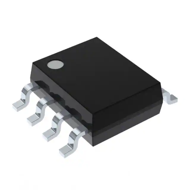
- Part No.:
- MAX9203ESA+T
- Manufacturer:
- Analog Devices Inc./Maxim Integrated
- Category:
- Comparators
- Package:
- 8-SOIC (0.154", 3.90mm Width)
- Datasheet:
-
 MAX9203ESA+T.pdf
- Description:
- IC COMPARATOR 1 W/LATCH 8SOIC
- Quantity:
- Payment:

- Shipping:

Inventory:3,916
Please send an inquiry. Send us your inquiry, and we will respond immediately.
Product details
Overview
MAX9203ESA+T from Maxim Integrated is a single high-speed voltage comparator with TTL-compatible output and latch input, designed for precision signal discrimination in timing-critical circuits. It delivers 7ns typical propagation delay at 5mV overdrive, consumes only 9mW at +5V supply, supports ±5V or +5V-to-+10V analog supplies with rail-to-rail common-mode input range, and operates across –40°C to +85°C - ideal for high-speed A/D converter front-ends and line receivers.
For engineers reviewing the MAX9203ESA+T datasheet, MAX9203ESA+T pinout, MAX9203ESA+T application, or MAX9203ESA+T equivalent, this page provides verified electrical parameters, latch timing constraints (tS = 2ns, tN = 1ns), SO-8 package mechanical data, real-world comparator use cases, and two validated alternative parts with documented functional and interface differences.
Technical Context
The MAX9203ESA+T implements a bipolar comparator core with active internal TTL pullups and a dedicated latch input that freezes output state on logic-low assertion. Its analog inputs accept common-mode voltages down to VEE (including ground when VEE = GND), enabling single-supply operation with input sensing referenced to system ground.
It requires separate VCC (analog positive), VEE (analog negative/substrate), VDD (digital +5V), and GND connections. The latch function is synchronous and edge-triggered, with defined setup (2ns), hold (1ns), and disable pulse width (8ns) requirements - not present in the latch-free MAX9201 variant.
Key Specifications
| Parameter | Value and Actual Design Meaning |
|---|---|
| Propagation Delay | 7ns typical at 5mV overdrive - enables sampling of >100MHz signals with minimal timing uncertainty. |
| Supply Configuration | Separate VCC/VEE (±5V or +5V–+10V analog) and VDD (+5V digital) - isolates analog signal path from digital noise. |
| Input Common-Mode Range | VEE – 0.1V to VCC – 2.25V - supports ground-referenced inputs in single-supply systems (VEE = GND). |
| Output Drive | TTL-compatible: VOH ≥ 3.0V @ 1mA, VOL ≤ 0.4V @ 8mA - directly interfaces with LS-TTL and standard logic families. |
| Latch Timing | tS = 2ns, tN = 1ns, tPW(D) = 8ns - defines minimum valid window for capturing input transitions before latch assertion. |
| Power Consumption | 9mW per comparator at +5V - reduces thermal load in dense mixed-signal PCB layouts. |
| Input Offset Voltage | 7.5mV max over temperature - ensures stable threshold detection in precision trigger applications. |
Pinout & Package
MAX9203ESA+T is housed in an 8-pin narrow SO (Small Outline) package, 3.9mm × 4.9mm body, 1.27mm pitch, with gull-wing leads. Pin 1 marked by beveled corner.
| Pin | Circuit Role | Design Meaning |
|---|---|---|
| 1 | VCC | Positive analog supply input - must be decoupled locally; supports +5V to +10V. |
| 2 | IN+ | Non-inverting input - accepts common-mode voltages down to VEE (GND in single-supply mode). |
| 3 | IN− | Inverting input - differential pair input node; matched impedance critical for high-speed stability. |
| 4 | VEE | Analog negative supply and substrate connection - tied to GND for single-supply operation. |
| 5 | LATCH | Active-low latch control - drives output into transparent mode when high; holds last state when low. |
| 6 | GND | Digital ground reference - separate from analog substrate (VEE) to minimize coupling noise. |
| 7 | OUT | TTL-compatible output - internally pulled up; sinks up to 8mA, sources ≥1mA at VOH ≥ 3.0V. |
| 8 | VDD | +5V digital supply - powers latch logic and output stage; must be clean and well-decoupled. |
Key Features
| Feature | Design Value |
|---|---|
| Rail-to-rail input common-mode range | Enables ground-sensing in single-supply configurations without level-shifting circuitry. |
| 7ns propagation delay with 5mV overdrive | Supports accurate timing capture in high-speed data sampling and clock recovery paths. |
| Dedicated TTL latch input | Allows synchronous freezing of comparator output state for time-aligned digital acquisition. |
| 9mW power dissipation at +5V | Reduces board-level heat generation and simplifies thermal management in multi-comparator systems. |
| Separate analog/digital supplies | Minimizes digital switching noise coupling into sensitive analog input stages via independent VCC/VEE and VDD/GND paths. |
Applications
| High-Speed A/D Converter Front-End | Line Receiver with Signal Restoration |
|---|---|
|
Use Scenario: Capturing fast analog transients prior to digitization in flash or pipeline ADC architectures. IC Role / Device Role / Timing Role: Single comparator acting as high-speed threshold detector feeding sample-and-hold or encoder logic. Use Value: 7ns delay and 1.0ns fall time ensure precise edge alignment between analog event and digital sampling clock. |
Use Scenario: Recovering degraded digital signals over long cables or noisy interconnects. IC Role / Device Role / Timing Role: Comparator restoring logic levels and slew rate of attenuated or jittered NRZ signals. Use Value: Input common-mode range including VEE allows direct interfacing to AC-coupled lines referenced to system ground. |
| PWM Timing Control Circuit | Threshold Detector in V/F Converter |
|
Use Scenario: Generating precise duty-cycle-modulated outputs based on analog control voltage thresholds. IC Role / Device Role / Timing Role: Latched comparator holding comparison result during PWM period to stabilize gate drive timing. Use Value: Defined latch timing (tS = 2ns, tN = 1ns) guarantees deterministic capture of control voltage edges within PWM cycle boundaries. |
Use Scenario: Converting analog sensor outputs (e.g., temperature, pressure) into proportional frequency signals. IC Role / Device Role / Timing Role: High-speed comparator detecting zero-crossings or fixed thresholds in integrator-based V/F topologies. Use Value: Low 7.5mV max input offset ensures <0.15% full-scale error in 5V-range V/F conversion systems. |
Equivalent & Alternatives
The following parts are listed as comparable options for similar high-speed voltage comparator applications.
| Alternative Part | Technical Difference | Application Difference | Selection Advice |
|---|---|---|---|
| LM311DR | No latch input; open-collector output requiring external pullup; 115ns propagation delay; wider supply range (±15V). | Not suitable for synchronous latching or sub-10ns timing-critical sampling; better for general-purpose industrial threshold detection. | Select LM311DR only when latch functionality is unnecessary and slower response is acceptable. |
| MAX903ESA+ | Legacy predecessor; 14ns propagation delay; 18mW power; no latch; same SO-8 package but incompatible pinout (no LATCH pin). | Cannot replace MAX9203ESA+T without PCB redesign due to missing LATCH function and different pin mapping. | Choose MAX903ESA+ only for cost-sensitive legacy upgrades where latch capability and 7ns speed are not required. |
Compared with LM311DR and MAX903ESA+, the MAX9203ESA+T uniquely combines sub-10ns speed, integrated latch control, and TTL output drive in an SO-8 package - making it the only option for synchronously sampled, low-latency comparator applications without external logic or layout changes.
Availability
MAX9203ESA+T is available at Aetrix Electronics and suitable for high-speed A/D converters, line receivers, and PWM timing circuits requiring stable component supply, consistent parametric performance, and long-term industrial temperature support (–40°C to +85°C).
Supply support for MAX9203ESA+T includes scheduled delivery planning, volume procurement assistance, BOM continuity management, traceable sourcing, and lifecycle availability coordination for OEM customers, industrial embedded developers, connected-device designers, and electronics production programs.
Manufacturer
Maxim Integrated (now part of Analog Devices) designs precision analog, mixed-signal, and power management ICs for industrial, communications, and computing applications.
The MAX920x family was developed specifically for high-speed, low-power voltage comparison in data acquisition and signal conditioning systems - emphasizing speed, latch synchronization, and supply flexibility over general-purpose comparators.
FAQ
What is the maximum operating temperature range for the MAX9203ESA+T?
The MAX9203ESA+T is rated for continuous operation from –40°C to +85°C. This industrial temperature range is guaranteed by design and confirmed in the Absolute Maximum Ratings table. All electrical specifications, including propagation delay and input offset voltage, are specified across this full range. The device's junction temperature must not exceed +150°C under any operating condition.
Does the MAX9203ESA+T require separate analog and digital ground planes?
Yes - the MAX9203ESA+T uses distinct VEE (analog negative/substrate) and GND (digital ground) pins, and optimal performance requires physically separated analog and digital ground regions on the PCB. This separation prevents digital switching noise from modulating the analog input stage. The datasheet explicitly recommends separate decoupling for VCC and VDD, and layout guidance mandates low-inductance ground planes with short lead lengths.
Can the MAX9203ESA+T operate from a single +5V supply?
Yes - the MAX9203ESA+T supports single-supply operation by tying VEE to GND and applying +5V to both VCC and VDD. In this configuration, the input common-mode range extends from GND to VCC – 2.25V (i.e., 0V to +2.75V), enabling ground-referenced signal detection. The latch input remains fully functional, and all timing specifications apply under this condition.
What is the purpose of the LATCH pin on the MAX9203ESA+T?
The LATCH pin on the MAX9203ESA+T controls synchronous output capture: when driven high, the comparator operates transparently; when driven low, the current output state is held regardless of subsequent input changes. This function enables precise timing alignment in sampling systems. Critical timing parameters include 2ns minimum setup time (tS) and 1ns minimum hold time (tN), ensuring reliable edge-triggered latching.
How does the MAX9203ESA+T differ from the MAX9201 and MAX9202 in terms of channel count and latch capability?
The MAX9203ESA+T is a single-channel comparator with one LATCH input and one OUT pin. In contrast, the MAX9201 is quad-channel (four comparators, no latch), and the MAX9202 is dual-channel (two comparators, each with dedicated LATCH and OUT pins). All three share identical electrical specs per channel (7ns delay, 9mW, TTL output), but pin count, channel density, and latch allocation differ - making MAX9203ESA+T optimal for space-constrained single-comparator designs requiring latching.
MAX9203ESA+T Specifications
- Product attributes
- Attribute value
- Manufacturer:
- Analog Devices Inc./Maxim Integrated
- Package/Case:
- 8-SOIC (0.154", 3.90mm Width)
- Series:
- -
- Packaging:
- Tape & Reel (TR)
- Product Status:
- Active
- Type:
- with Latch
- Number of Elements:
- 1
- Output Type:
- TTL
- Voltage - Supply, Single/Dual (±):
- 4.75V ~ 10.5V, ±2.375V ~ 5.75V
- :
- 4mV @ ±5V
- Voltage - Input Offset (Max):
- 5µA @ ±5V
- Current - Input Bias (Max):
- -
- Current - Output (Typ):
- 2mA, 1.6mA, 800µA
- Current - Quiescent (Max):
- 86.02dB CMRR, 86.02dB PSRR
- CMRR, PSRR (Typ):
- -
- Propagation Delay (Max):
- -
- Hysteresis:
- -40°C ~ 85°C
- Operating Temperature:
- -
- Grade:
- -
- Qualification:
- Surface Mount
- :
- 8-SOIC
MAX9203ESA+T FAQ
1.How can I place an order for MAX9203ESA+T through Aetrix?
Please submit a Request for Quotation (RFQ) for MAX9203ESA+T on Aetrix. Our sales agent will provide a competitive quotation and guide you through the order confirmation once you accept the terms.
2.Are the price and stock information for MAX9203ESA+T reliable?
The price and inventory of MAX9203ESA+T are updated periodically and may fluctuate due to market conditions. Stock and pricing data are typically refreshed every 24 hours. Quotation validity for MAX9203ESA+T is usually 5 days.
3.What payment methods are accepted for MAX9203ESA+T?
We accept Wire Transfer, PayPal, Credit Card, Western Union, MoneyGram, and Escrow for MAX9203ESA+T transactions.
Note: Certain payment methods may incur a processing fee.
4.How is shipping managed for MAX9203ESA+T?
MAX9203ESA+T orders can be shipped via leading logistics carriers, including DHL, UPS, FedEx, TNT, or Registered Mail.
Once your MAX9203ESA+T order is processed, you will receive an email with the shipment details and tracking number.
Note: Tracking information may take up to 24 hours to appear. Express delivery typically takes 3–5 business days.
5.How can I obtain technical support or documentation for MAX9203ESA+T?
For technical support, including MAX9203ESA+T datasheets, pinout diagrams, or application guidance, please contact our engineering support team. They can provide detailed documentation and assistance for your MAX9203ESA+T requirements.
6.How does Aetrix verify that MAX9203ESA+T is sourced from the original manufacturer or authorized distributors?
All MAX9203ESA+T products on Aetrix are procured from qualified distributors and authorized channels. Our dedicated quality assurance team conducts strict verification, including traceability checks and, if necessary, third-party testing. This ensures that MAX9203ESA+T meets industry standards.
7.What is the process for return or replacement of MAX9203ESA+T?
All MAX9203ESA+T units undergo pre-shipment inspection (PSI). If there is an issue with MAX9203ESA+T, returns or replacements are accepted under the following conditions:
1.Quantity discrepancies, incorrect items, or visible external defects (such as breakage or corrosion), acknowledged by Aetrix.
2.The issue is reported within 90 days of delivery.
3.The MAX9203ESA+T part is unused and in its original packaging.
Return procedure for MAX9203ESA+T:
1.Submit a request within 90 days.
2.Obtain a Return Material Authorization (RMA) from Aetrix.
MAX9203ESA+T Tags

-
LM2903DR
Texas Instruments

-
LM339DR
Texas Instruments

-
LM339PWR
Texas Instruments

-
LM393DT
STMicroelectronics
-
LM2901PWR
Texas Instruments
-
LM2903DT
STMicroelectronics
-
LM393DR
Texas Instruments
-
LM239DR
Texas Instruments
-
LM339APWR
Texas Instruments

-
LM2903P
Texas Instruments
-
LM393ADR
Texas Instruments
-
NCX2200GMAZ
NXP USA Inc.
Tech Hub

An engineering guide to LED driver operation, constant-current and constant-voltage outputs, linear and switching topologies, dimming, IC selection, calculations, replacement compatibility, and fault c…

Operational amplifier guide covering op amp basics, feedback, ideal vs real op amps, common configurations, buffer circuits, offset, bias current, gain-bandwidth, slew rate, rail-to-rail limits and sel…

Jumper cables guide covering safe connection order, red and black clamp placement, final ground connection, cable gauge, length, clamp quality, copper vs CCA cables, jump starter comparison and battery…

LDO regulator guide covering low dropout voltage, power dissipation, thermal design, PSRR, output noise, capacitor stability, adjustable LDO circuits, LDO vs buck converter and datasheet selection chec…

Conditional Access Module guide covering CAM meaning, CI/CI+ interface, smart card authorization, DVB security workflow, TV and set-top box compatibility, internal electronics, ESD protection, connecto…

Guide to electronic component obsolescence covering EOL risk, PCN/PDN notices, last-time buy planning, replacement options, form-fit-function validation, counterfeit risk and BOM lifecycle management.

18650 battery guide covering lithium-ion cell basics, 3.6V/3.7V voltage, 4.2V charging, mAh and Wh capacity, protected cells, chargers, BMS, series-parallel packs, holders, welding and sourcing checks.…

Hall effect sensor guide covering working principle, linear and digital sensors, Arduino circuits, current sensing, speed detection, automotive applications, A3144 examples, signal filtering and datash…

Product Change Notification guide for electronic components, covering PCN meaning, PCN vs PDN/EOL, common change types, risk levels, form-fit-function review, engineering validation, BOM control, LTB/L…

A practical guide to blend door actuators, covering HVAC function, symptoms, location, AC and heater issues, reset and calibration, replacement cost, electrical diagnosis, compatibility checks, and rep…


