
 My Inquiry
 My Account


Analog Devices Inc./Maxim Integrated MAX9208EAI+T
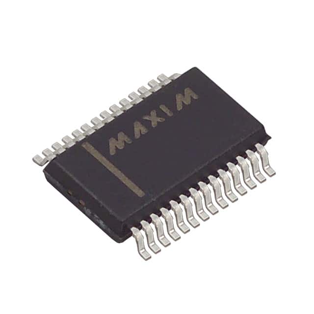
- Part No.:
- MAX9208EAI+T
- Manufacturer:
- Analog Devices Inc./Maxim Integrated
- Category:
- Serializers, Deserializers
- Package:
- 28-SSOP (0.209", 5.30mm Width)
- Datasheet:
-
 MAX9208EAI+T.pdf
- Description:
- IC DESERIALIZER LVDS 28-SSOP
- Quantity:
- Payment:

- Shipping:

Inventory:3,009
Please send an inquiry. Send us your inquiry, and we will respond immediately.
Product details
Overview
MAX9208EAI+T from Maxim Integrated is a 10-bit BLVDS deserializer IC that converts high-speed serial LVDS data streams (400–600Mbps) into parallel LVCMOS/LVTTL outputs and a recovered clock, used in backplane and cable-based interconnects for telecom infrastructure and industrial imaging systems.
For engineers reviewing the MAX9208EAI+T datasheet, MAX9208EAI+T pinout, MAX9208EAI+T application, or MAX9208EAI+T equivalent, key selection criteria include its 40–60MHz reference clock range, 320ps peak-to-peak input jitter tolerance at 60MHz, programmable RCLK strobe edge, and support for hot-insertion without system interruption.
Technical Context
The MAX9208EAI+T implements a PLL-based clock recovery architecture synchronized to incoming BLVDS serial data, achieving frequency lock, bit lock, and frame lock to generate a word-aligned 10-bit parallel output and parallel-rate clock. It supports both point-to-point and bus topologies with 54Ω–100Ω differential termination.
Its digital deframing logic identifies embedded framing bits (start high + end low) to reconstruct 10-bit words from 12-bit serial symbols. Initialization supports pseudorandom data lock (no sync pattern required) and fast sync-pattern lock (≤42 × tRFCP), enabling robust operation in hot-plug and dynamic link scenarios.
Key Specifications
| Parameter | Value and Actual Design Meaning |
|---|---|
| Serial Data Rate | 400–600Mbps - Enables transmission of 10-bit parallel data over PCB traces or twisted-pair cables at up to 60MHz reference clock. |
| Reference Clock Range | 40–60MHz - Must be within ±200ppm stability; determines maximum deserialization throughput and timing margin. |
| Jitter Tolerance | 320ps (p-p) at 60MHz - Specifies maximum zero-to-peak deterministic jitter the device can tolerate before sampling error occurs. |
| Supply Current | 80–100mA (typ) at 60MHz - Measured under worst-case pattern load (CL = 15pF); impacts thermal design and power rail sizing. |
| Operating Temp | -40°C to +85°C - Industrial temperature grade suitable for base station, DSLAM, and network switch environments. |
| Power-Down Current | <1mA - Achieved when PWRDN = low; stops PLL and places ROUT_, RCLK, LOCK in high-impedance state. |
| Output Interface | 10-bit LVCMOS/LVTTL - Rout0–Rout9 outputs drive standard CMOS/TTL loads; RCLK provides synchronous strobe. |
Pinout & Package
MAX9208EAI+T is housed in a 28-pin SSOP package (package code A28+4, outline 21-0056) with exposed pad not electrically connected. Pin spacing is 0.025", body width 0.209", and recommended land pattern per Maxim document 90-0095.
| Pin/Terminal | Circuit Role | Design Meaning |
|---|---|---|
| 1, 12, 13 | AGND | Analog ground reference for RI+, RI-, REFCLK, and internal PLL circuitry; requires separate low-noise routing. |
| 2 | RCLK_R/F | LVTTL/LVCMOS input controlling RCLK edge used to strobe ROUT_: high = rising edge, low = falling edge. |
| 3 | REFCLK | PLL reference clock input (40–60MHz); must meet ±200ppm stability and 30–70% duty cycle requirements. |
| 4, 11 | AVCC | +3.3V analog supply; bypassed with 0.1µF + 0.001µF ceramics to AGND near each pin. |
| 5, 6 | RI+, RI- | BLVDS differential serial data inputs; accept 0.1–1.2V differential swing and support fail-safe biasing. |
| 7 | PWRDN | Active-high power-down control: drives ROUT_, RCLK, LOCK into high-Z and stops PLL when low. |
| 8 | REN | Active-high output enable: disables ROUT_ and RCLK drivers while preserving LOCK status and PLL lock. |
| 9 | RCLK | Recovered parallel-rate clock output (LVCMOS/LVTTL); used to latch ROUT_ on selected edge per RCLK_R/F. |
| 10 | LOCK | Open-drain status indicator: low = valid lock (frequency + phase + frame sync achieved); remains active during REN=low. |
| 14, 20, 22 | DGND | Digital ground return for ROUT_, RCLK, LOCK, and logic inputs; separated from AGND for noise isolation. |
| 15–19, 24–28 | ROUT9–ROUT0 | 10-bit parallel LVCMOS/LVTTL data outputs; valid on second selected RCLK edge after LOCK goes low. |
| 21, 23 | DVCC | +3.3V digital supply; bypassed with 0.1µF + 0.001µF ceramics to DGND near each pin. |
Key Features
| Feature | Design Value |
|---|---|
| Standalone deserializer architecture | Operates without paired serializer IC; accepts BLVDS input directly-enables unidirectional link upgrades without full SerDes redesign. |
| Programmable RCLK strobe edge | RCLK_R/F pin selects rising or falling edge for ROUT_ latching-allows timing alignment flexibility across varying board trace delays. |
| Hot-insertion synchronization | Locks to pseudorandom data without sync patterns-permits live insertion into active serial links without disrupting other deserializers on shared bus. |
| Wide differential input impedance range | Supports 54Ω–100Ω media termination-compatible with both heavily loaded buses and double-terminated point-to-point interfaces. |
| Fail-safe input biasing | Internal circuit pulls undriven RI+/RI- high-prevents undefined LOCK behavior during cable disconnect or serializer power loss. |
Applications
| Cellular Base Station Backhaul | Digital Cross-Connect Systems |
|---|---|
Use Scenario: Transmitting 10-bit I/Q data between RF transceivers and baseband processors over long PCB traces or twin-ax cables. IC Role / Device Role / Timing Role: Deserializes high-speed BLVDS stream from MAX9207 serializer into parallel LVCMOS data and recovered clock for FPGA interface. Use Value: Eliminates clock-to-data skew across 10-bit bus; enables 600Mbps throughput with 320ps jitter margin at 60MHz reference clock. |
Use Scenario: Interfacing line cards with switching fabric ASICs using compact differential cabling instead of wide parallel buses. IC Role / Device Role / Timing Role: Converts serialized control and payload data from remote modules into synchronous parallel format for local switching logic. Use Value: Reduces connector pin count by >50% versus parallel bus; maintains deterministic latency via frame-locked RCLK output. |
| DSLAM Line Card Interconnect | Industrial Machine Vision Cameras |
Use Scenario: Linking multi-port DSL line drivers to central aggregation ASICs in space-constrained DSLAM chassis. IC Role / Device Role / Timing Role: Receives BLVDS data from upstream MAX9205 serializers and delivers aligned 10-bit parallel outputs to DSP cores. Use Value: Supports 40–60MHz REFCLK range matching common DSL PHY clock domains; operates reliably at -40°C to +85°C. |
Use Scenario: Transferring high-resolution image sensor data (e.g., 10-bit CMOS sensors) from camera head to processing unit over flexible twisted-pair harness. IC Role / Device Role / Timing Role: Deserializes embedded-clock BLVDS stream into parallel pixel data synchronized to recovered RCLK. Use Value: Enables hot-plug camera replacement without interrupting video stream on other channels; tolerates cable-induced jitter up to 320ps p-p. |
Equivalent & Alternatives
The following parts are listed as comparable options for similar deserializer applications.
| Alternative Part | Technical Difference | Application Difference | Selection Advice |
|---|---|---|---|
| DS92LV1224 | Pin-compatible but rated for 66MHz max REFCLK and 660Mbps; higher jitter tolerance (400ps p-p at 66MHz); requires external VDDQ bias. | Preferred in new designs targeting >60MHz clock rates or requiring extended jitter margin; not drop-in due to different power sequencing. | Select DS92LV1224 when REFCLK exceeds 60MHz or system-level jitter budget demands >320ps margin. |
| MAX9206EAI+ | Same package and pinout; lower REFCLK range (16–45MHz); 720ps jitter tolerance at 45MHz; 450Mbps max data rate. | Suitable for cost-sensitive or lower-bandwidth links (e.g., legacy telecom modules); shares layout but not electrical interchangeability. | Choose MAX9206EAI+ only if reference clock is ≤45MHz and jitter environment is more severe than 320ps. |
Compared with DS92LV1224 and MAX9206EAI+, the MAX9208EAI+T offers optimal balance of speed (600Mbps), jitter resilience (320ps), and industrial temperature support in a proven 28-pin SSOP footprint-making it ideal for mid-range telecom and imaging interconnects where 60MHz operation is required but 66MHz headroom is unnecessary.
Availability
MAX9208EAI+T is available at Aetrix Electronics and suitable for cellular base station backhaul, DSLAM line card interconnect, and industrial machine vision camera designs requiring stable component supply across extended temperature ranges and long production lifecycles.
Supply support for MAX9208EAI+T includes scheduled delivery planning, volume procurement assistance, BOM continuity management, traceable sourcing, and lifecycle availability coordination for OEM customers, industrial embedded developers, connected-device designers, and electronics production programs.
Manufacturer
Maxim Integrated (now part of Analog Devices) is a U.S.-based semiconductor company specializing in high-performance analog, mixed-signal, and RF solutions for industrial, communications, and automotive markets.
The MAX9206/MAX9208 product line was designed specifically for high-reliability, low-skew serial-to-parallel conversion in telecom infrastructure and imaging systems-emphasizing jitter tolerance, hot-plug capability, and compatibility with legacy BLVDS serializer families like MAX9205/MAX9207.
FAQ
What is the maximum serial data rate supported by the MAX9208EAI+T?
The MAX9208EAI+T supports a maximum serial data rate of 600Mbps, achieved when operating with a 60MHz reference clock and 10-bit parallel data width. This rate is specified across the full -40°C to +85°C temperature range and assumes compliant BLVDS input signal integrity and proper termination. The MAX9208EAI+T achieves this performance while maintaining 320ps peak-to-peak input jitter tolerance at 60MHz.
Does the MAX9208EAI+T require an external serializer to function?
No, the MAX9208EAI+T functions as a standalone deserializer and does not require an external serializer to operate. It accepts raw BLVDS serial input (RI+/RI-) and recovers clock and data autonomously. However, for complete SerDes link implementation, it is commonly paired with Maxim's MAX9207 or MAX9205 serializers-but the MAX9208EAI+T itself needs no companion IC to perform deserialization.
How does the RCLK_R/F pin affect timing behavior in the MAX9208EAI+T?
The RCLK_R/F pin on the MAX9208EAI+T selects whether the ROUT_ data outputs are latched on the rising edge (RCLK_R/F = high) or falling edge (RCLK_R/F = low) of the recovered RCLK signal. This programmability allows system designers to compensate for board-level propagation delays and align data capture timing precisely with downstream logic-critical for meeting setup/hold margins in FPGA or ASIC interfaces.
Can the MAX9208EAI+T maintain lock during hot insertion?
Yes, the MAX9208EAI+T supports hot insertion via its pseudorandom data lock capability. It can achieve lock to arbitrary BLVDS data patterns without requiring sync patterns-eliminating the need to pause or reconfigure the serial link. This allows safe insertion of a new MAX9208EAI+T-equipped module into an active system, with LOCK going low within typical lock times (e.g., ~0.144µs average at 40MHz) once valid data is detected.
What is the purpose of the LOCK signal in the MAX9208EAI+T?
The LOCK signal in the MAX9208EAI+T is an open-drain status output indicating successful acquisition of frequency lock, phase lock, and frame synchronization to the incoming BLVDS stream. LOCK goes low only when all three conditions are met-and remains low as long as valid framing is maintained. It stays active even when REN = low, enabling system-level monitoring of serial link health independent of output driver state.
MAX9208EAI+T Specifications
- Product attributes
- Attribute value
- Manufacturer:
- Analog Devices Inc./Maxim Integrated
- Series:
- -
- Package/Case:
- 28-SSOP (0.209", 5.30mm Width)
- Packaging:
- Tape & Reel (TR)
- Product Status:
- Active
- Function:
- Deserializer
- Data Rate:
- 600Mbps
- Input Type:
- LVDS
- Output Type:
- LVCMOS, LVTTL
- Number of Inputs:
- 1
- Number of Outputs:
- 10
- Voltage - Supply:
- 3V ~ 3.6V
- Operating Temperature:
- -40°C ~ 85°C (TA)
- Grade:
- -
- Qualification:
- -
- Mounting Type:
- Surface Mount
- Supplier Device Package:
- 28-SSOP
MAX9208EAI+T FAQ
1.How can I place an order for MAX9208EAI+T through Aetrix?
Please submit a Request for Quotation (RFQ) for MAX9208EAI+T on Aetrix. Our sales agent will provide a competitive quotation and guide you through the order confirmation once you accept the terms.
2.Are the price and stock information for MAX9208EAI+T reliable?
The price and inventory of MAX9208EAI+T are updated periodically and may fluctuate due to market conditions. Stock and pricing data are typically refreshed every 24 hours. Quotation validity for MAX9208EAI+T is usually 5 days.
3.What payment methods are accepted for MAX9208EAI+T?
We accept Wire Transfer, PayPal, Credit Card, Western Union, MoneyGram, and Escrow for MAX9208EAI+T transactions.
Note: Certain payment methods may incur a processing fee.
4.How is shipping managed for MAX9208EAI+T?
MAX9208EAI+T orders can be shipped via leading logistics carriers, including DHL, UPS, FedEx, TNT, or Registered Mail.
Once your MAX9208EAI+T order is processed, you will receive an email with the shipment details and tracking number.
Note: Tracking information may take up to 24 hours to appear. Express delivery typically takes 3–5 business days.
5.How can I obtain technical support or documentation for MAX9208EAI+T?
For technical support, including MAX9208EAI+T datasheets, pinout diagrams, or application guidance, please contact our engineering support team. They can provide detailed documentation and assistance for your MAX9208EAI+T requirements.
6.How does Aetrix verify that MAX9208EAI+T is sourced from the original manufacturer or authorized distributors?
All MAX9208EAI+T products on Aetrix are procured from qualified distributors and authorized channels. Our dedicated quality assurance team conducts strict verification, including traceability checks and, if necessary, third-party testing. This ensures that MAX9208EAI+T meets industry standards.
7.What is the process for return or replacement of MAX9208EAI+T?
All MAX9208EAI+T units undergo pre-shipment inspection (PSI). If there is an issue with MAX9208EAI+T, returns or replacements are accepted under the following conditions:
1.Quantity discrepancies, incorrect items, or visible external defects (such as breakage or corrosion), acknowledged by Aetrix.
2.The issue is reported within 90 days of delivery.
3.The MAX9208EAI+T part is unused and in its original packaging.
Return procedure for MAX9208EAI+T:
1.Submit a request within 90 days.
2.Obtain a Return Material Authorization (RMA) from Aetrix.
MAX9208EAI+T Tags

-
SN65HVS880PWPR
Texas Instruments
-
SN65HVS882PWPR
Texas Instruments

-
FIN3386MTDX
onsemi
-
FIN3385MTDX
onsemi

-
SN65LV1023ARHBR
Texas Instruments
-
SN65LV1023ADBR
Texas Instruments
-
SN65LV1224BDBR
Texas Instruments

-
SN65LVDS93ADGGR
Texas Instruments
-
SN65LVDS93DGGR
Texas Instruments

-
TDES954RGZT
Texas Instruments
-
SN65LV1224BRHBT
Texas Instruments
-
DS90UB914QSQE/NOPB
Texas Instruments
Tech Hub

A practical engineering guide to 3.3V and 5V logic compatibility, input thresholds, resistor dividers, translator ICs, MOSFET level shifting, I2C pull-ups, timing limits and power-sequencing risks.

The 74HC595 uses push-pull logic outputs, while the TPIC6B595 uses 50 V open-drain DMOS sinks for higher-power loads. This guide compares timing, current limits, 3.3 V interfacing, load wiring, thermal…

The 74HC595 converts serial data into eight stable parallel outputs. This guide covers pin functions, shift and storage timing, OE and MR behavior, drive-current limits, cascading, voltage compatibilit…

A technical comparison of level-sensitive latches and edge-triggered flip-flops, covering timing windows, setup and hold limits, master–slave operation, time borrowing, race-through, HDL inference and…

A D latch stores one bit while Enable controls when data can pass. This reference covers gate-level operation, truth tables, transparency, setup and hold timing, LE versus OE, common ICs and practical …

An SR latch stores one bit through cross-coupled feedback. This engineering reference covers NOR and NAND implementations, truth tables, forbidden-state recovery, gated operation, switch debouncing, fa…

Latch circuits retain one bit through feedback. This technical reference covers SR and D latches, truth tables, transparency, timing limits, latch-versus-flip-flop behavior, applications and common log…

An engineering guide to LED driver operation, constant-current and constant-voltage outputs, linear and switching topologies, dimming, IC selection, calculations, replacement compatibility, and fault c…

Operational amplifier guide covering op amp basics, feedback, ideal vs real op amps, common configurations, buffer circuits, offset, bias current, gain-bandwidth, slew rate, rail-to-rail limits and sel…

Jumper cables guide covering safe connection order, red and black clamp placement, final ground connection, cable gauge, length, clamp quality, copper vs CCA cables, jump starter comparison and battery…


