
 My Inquiry
 My Account


Analog Devices Inc./Maxim Integrated MAXM17546ALY#
- Part No.:
- MAXM17546ALY#
- Manufacturer:
- Analog Devices Inc./Maxim Integrated
- Category:
- DC DC Converters
- Package:
- 29-PowerBLGA Module
- Datasheet:
-
 MAXM17546ALY#.pdf
- Description:
- IC REG BUCK ADJ 5A 29SIP
- Quantity:
- Payment:

- Shipping:

Inventory:112
Please send an inquiry. Send us your inquiry, and we will respond immediately.
Product details
Overview
The MAXM17546ALY# from Maxim Integrated is a fully integrated, synchronous step-down power module combining controller, dual n-channel MOSFETs, shielded inductor, and compensation circuitry in a 29-pin SiP package. It delivers up to 5A continuous output current across 0.9V–12V adjustable output voltage, operates from 4.5V–42V input, and supports PWM/DCM/PFM control modes-enabling compact, high-efficiency point-of-load regulation for FPGA, DSP, and industrial base-station applications.
For engineers reviewing the MAXM17546ALY# datasheet, MAXM17546ALY# pinout, MAXM17546ALY# application, or MAXM17546ALY# equivalent, this page provides verified technical context, validated pin functions, confirmed thermal and electrical specifications, and real-world design implications-including soft-start programmability, RESET monitoring, EXTVCC efficiency optimization, and mode-selectable transient response behavior.
Technical Context
The MAXM17546ALY# implements peak-current-mode control with internal transconductance error amplifier, slope compensation, and cycle-by-cycle current limiting. Its architecture integrates dual MOSFET drivers (high-side and low-side), bootstrap LDO (BST), auxiliary EXTVCC switchover logic, and hiccup-mode overload protection-enabling stable operation across -40°C to +125°C ambient with junction temperatures up to +150°C.
It features three configurable operating modes via the MODE/SYNC pin: PWM (constant-frequency, negative inductor current allowed), PFM (pulse-skipping, ultra-low quiescent current at light loads), and DCM (discontinuous conduction, fixed frequency down to lighter loads than PFM). Frequency is adjustable from 100kHz to 2.2MHz using an external RT resistor, with synchronization capability for noise-sensitive systems.
Key Specifications
| Parameter | Value and Actual Design Meaning |
|---|---|
| Input Voltage Range | 4.5V to 42V - supports wide industrial and automotive supply rails without pre-regulation. |
| Output Current | Up to 5A continuous - sufficient for FPGA core, DSP I/O, or multi-rail point-of-load conversion. |
| Output Voltage Range | 0.9V to 12V, adjustable via FB resistor divider - covers processor cores, memory, and analog subsystems. |
| Switching Frequency | 100kHz to 2.2MHz, set by RT resistor - enables EMI optimization and small external capacitor selection. |
| FB Regulation Accuracy | ±1.5% over -40°C to +125°C - ensures stable output under full industrial temperature range. |
| Thermal Shutdown | 165°C threshold with 10°C hysteresis - protects against sustained overload or poor heatsinking. |
| RESET Output | Open-drain, asserts when VOUT falls below 92.5% of nominal - provides reliable power-good signaling for sequenced systems. |
Pinout & Package
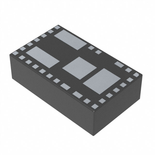
Package: 29-pin, 9mm × 15mm × 4.32mm system-in-package (SiP) with thermally enhanced exposed pads (EP1/EP2/EP3) tied to PGND/SGND for efficient heat dissipation. RoHS-compliant, reflow-solderable, compatible with automated PCB assembly.
| Pin/Terminal | Circuit Role | Design Meaning |
|---|---|---|
| VCC (Pin 1) | 5V LDO output | Internally bypassed with 2.2µF capacitor; powers internal circuitry-no external connection permitted. |
| RESET (Pin 2) | Open-drain power-good signal | Asserts low if FB drops below 92.5% of set value; deasserts after 1024 cycles once FB rises above 95.5%. |
| RT (Pin 3) | Frequency programming node | Resistor to SGND sets switching frequency (100kHz–2.2MHz); open = 450kHz default. |
| SGND (Pin 4) | Analog ground reference | Separate from PGND to minimize noise coupling into feedback and control loops. |
| CF (Pin 5) | Compensation network node | Connects 2.2pF capacitor to FB-fully integrated loop compensation eliminates external type-II/type-III networks. |
| FB (Pin 6) | Feedback input | Monitors output via resistor divider; regulation accuracy ±1.5% over full temperature range. |
| SS (Pin 7) | Soft-start timing input | Capacitor to SGND sets ramp time-prevents inrush current and stabilizes startup sequence. |
| EN/UVLO (Pin 8) | Enable and input undervoltage lockout | Resistor to SGND sets rising/falling thresholds (1.215V/1.09V typ); open = enabled by default. |
| IN (Pins 9, 28) | Main power input | High-current path requiring local ceramic decoupling (e.g., 10µF GRM32ER71H106KA12) near pins. |
| PGND (Pins 10, 14–21, 27) | Power ground return | Multiple low-inductance paths for high di/dt switching currents-must be connected to large copper pour. |
| EXTVCC (Pin 11) | External LDO input | Accepts 4.7V–24V to bypass internal INLDO-improves efficiency at VIN > 12V. |
| BST (Pin 12) | Bootstrap capacitor node | Internally connected to LX via 0.1µF capacitor-no external components allowed. |
| LX (Pin 13) | Switching node | Internal connection between high-side and low-side MOSFETs-must remain unconnected externally. |
| OUT (Pins 22–25) | Regulated output | High-current output requiring bulk capacitance (e.g., 3×22µF GRM32ER71C226MEA8) to PGND. |
| DL (Pin 26) | Low-side gate driver output | Drives internal low-side MOSFET-no external connection permitted. |
| MODE/SYNC (Pin 29) | Control mode selection / clock sync | Open = PFM; SGND = PWM; VCC = DCM-also accepts external clock (1.1× to 1.4× fSW) for EMI reduction. |
Key Features
| Feature | Design Value |
|---|---|
| Integrated inductor + MOSFETs + controller | Reduces external BOM to only FB divider, SS cap, input/output caps, and optional RT-eliminates layout sensitivity and magnetics selection. |
| Three selectable control modes (PWM/DCM/PFM) | Enables trade-off between light-load efficiency (PFM), EMI predictability (PWM), and mid-load balance (DCM)-no firmware or external logic required. |
| Programmable soft-start and EXTVCC switchover | SS capacitor sets startup ramp; EXTVCC input improves efficiency by ~2–3% at VIN > 15V-critical for high-input industrial supplies. |
| Integrated thermal shutdown and hiccup-mode protection | 165°C trip with 10°C hysteresis prevents thermal runaway; hiccup mode limits average power during sustained short-circuit events. |
| RESET output with precise VOUT monitoring | Asserts at 92.5% VOUT, deasserts at 95.5% after 1024 cycles-supports reliable power sequencing in multi-rail systems without external supervisors. |
Applications
| FPGA and DSP Point-of-Load Regulator | Base-Station Point-of-Load Regulator |
|---|---|
|
Use Scenario: Powering 0.9V–1.2V core and 1.8V/3.3V I/O rails of Xilinx Kintex or TI C66x DSPs in compact telecom equipment. IC Role / Device Role / Timing Role: Primary DC-DC converter delivering regulated, low-noise, fast-transient power directly at the load. Use Value: Integrated inductor and MOSFETs reduce solution size by >40% vs discrete buck designs; PFM mode maintains >85% efficiency at 10mA load. |
Use Scenario: Supplying 5V/3.3V rails for RF front-end ICs, ADCs, and FPGAs in 4G/5G macro base stations operating at -40°C to +85°C. IC Role / Device Role / Timing Role: High-reliability, thermally robust power module meeting MIL-STD-810G shock/vibe and extended temperature requirements. Use Value: Junction temp rating to +150°C and 24°C/W θJA enable operation without forced air; RESET output interfaces directly with FPGA configuration logic. |
| Test and Measurement Equipment | HVAC and Building Control |
|
Use Scenario: Providing clean, low-ripple 5V/12V outputs for precision ADCs, DACs, and sensor excitation circuits in portable oscilloscopes and data loggers. IC Role / Device Role / Timing Role: Low-noise, tightly regulated supply with <6mV/A load regulation and <0.1mV/V line regulation. Use Value: CF/FB compensation eliminates external op-amps; PWM mode ensures constant switching frequency for EMI filtering predictability. |
Use Scenario: Powering microcontrollers, RS-485 transceivers, and environmental sensors in smart thermostats and building automation controllers deployed in unconditioned spaces. IC Role / Device Role / Timing Role: Industrial-grade DC-DC converter with -40°C to +125°C operation and hiccup-mode fault containment. Use Value: EN/UVLO programmability allows brown-out detection at 12V system rail; EXTVCC input improves efficiency when powered from 24V HVAC bus. |
Equivalent & Alternatives
The following parts are listed as comparable options for similar high-integration, high-voltage step-down power module applications.
| Alternative Part | Technical Difference | Application Difference | Selection Advice |
|---|---|---|---|
| MAXM15462ALY# | Lower 3A output current, 4.5V–36V input, same 29-pin SiP footprint and pinout. | Suitable for lower-power MCU or sensor nodes where 5A headroom is unnecessary. | Select when board space and layout reuse are critical but full 5A capability is not required. |
| TPSM84624IRVCR | TI 6A module, 4.5V–60V input, different 10mm × 12.5mm package, non-pin-compatible. | Supports higher input voltages (e.g., 48V industrial buses) and greater output current margin. | Choose when extending input range beyond 42V or needing >5A peak capability-requires PCB redesign. |
Compared with MAXM15462ALY#, the MAXM17546ALY# delivers 67% higher output current in identical footprint; versus TPSM84624IRVCR, it offers tighter thermal resistance (24°C/W vs ~32°C/W on 4-layer board) and integrated EXTVCC switchover for improved efficiency at mid-range inputs.
Availability
The MAXM17546ALY# is available at Aetrix Electronics and suitable for FPGA and DSP point-of-load regulation, base-station power delivery, test-and-measurement instrumentation, and HVAC/building control systems requiring stable component supply, long-term lifecycle support, and RoHS-compliant manufacturing.
Supply support for MAXM17546ALY# includes scheduled delivery planning, volume procurement assistance, BOM continuity management, traceable sourcing, and lifecycle availability coordination for OEM customers, industrial embedded developers, connected-device designers, and electronics production programs.
Manufacturer
Maxim Integrated (now part of Analog Devices) designs high-performance analog, mixed-signal, and power management ICs for industrial, automotive, communications, and computing markets.
The MAXM17546ALY# belongs to the Himalaya power module family-engineered to deliver cooler, smaller, and simpler power solutions through full integration of magnetics, switches, and control in thermally optimized SiP packages.
FAQ
What is the maximum continuous output current of the MAXM17546ALY#?
The MAXM17546ALY# delivers up to 5A continuous output current across its full operating temperature range (-40°C to +125°C ambient), verified under natural convection on a 4-layer evaluation board. Derating applies above +85°C ambient per the output current vs. ambient temperature curve (Figure toc48), where 5A is maintained up to +85°C and reduces linearly to ~3.5A at +125°C.
Can the MAXM17546ALY# operate with an input voltage below 4.5V?
No-the absolute minimum input voltage for functional operation of the MAXM17546ALY# is 4.5V, as specified in both the Absolute Maximum Ratings and Electrical Characteristics tables. Operation below this threshold may result in undefined behavior, failure to start, or violation of FB regulation accuracy. The device enters shutdown if VIN falls below the EN/UVLO falling threshold (1.09V typ) at the EN/UVLO pin-but this does not override the 4.5V minimum VIN requirement.
How does the EXTVCC pin improve efficiency in the MAXM17546ALY#?
The EXTVCC pin on the MAXM17546ALY# accepts an external 4.7V–24V supply to power the internal 5V LDO, bypassing the less-efficient INLDO path. When VIN exceeds ~12V, routing a clean 5V–12V rail to EXTVCC reduces power loss in the input LDO stage, improving overall efficiency by 2–3%-particularly beneficial in high-input industrial applications like 24V HVAC or 36V base-station supplies.
Is the MAXM17546ALY# pin-compatible with other Himalaya modules?
The MAXM17546ALY# uses the standard 29-pin Himalaya SiP footprint (land pattern 90-100055), but pin compatibility is limited to same-family variants with identical pin function mapping-such as the MAXM15462ALY#. It is not pin-compatible with MAXM17536 or MAXM17574 due to differences in MODE/SYNC behavior, RESET timing, and internal LDO architecture. Always verify pin descriptions and functional diagrams before substitution.
What is the purpose of the CF pin on the MAXM17546ALY#?
The CF pin on the MAXM17546ALY# is the compensation network node, requiring a 2.2pF capacitor connected to FB. This completes the internal type-II compensation network-eliminating the need for external resistors or capacitors in the feedback loop. The integrated compensation ensures stable operation across the full 0.9V–12V output range and -40°C to +125°C temperature range without manual tuning.
MAXM17546ALY# Specifications
- Product attributes
- Attribute value
- Manufacturer:
- Analog Devices Inc./Maxim Integrated
- Series:
- Himalaya
- Package/Case:
- 29-PowerBLGA Module
- Packaging:
- Tray
- Product Status:
- Active
- Type:
- -
- Number of Outputs:
- -
- Voltage - Input (Min):
- 4.5V
- Voltage - Input (Max):
- 42V
- Voltage - Output 1:
- -
- Voltage - Output 2:
- -
- Voltage - Output 3:
- -
- Voltage - Output 4:
- -
- Current - Output (Max):
- -
- Power (Watts):
- -
- Voltage - Isolation:
- -
- Applications:
- -
- Features:
- -
- Operating Temperature:
- -40°C ~ 125°C
- Efficiency:
- -
- Grade:
- -
- Qualification:
- -
- Mounting Type:
- Surface Mount
- Supplier Device Package:
- 29-SIP LGA (9x15)
- Control Features:
- -
- Approval Agency:
- -
- Standard Number:
- -
MAXM17546ALY# FAQ
1.How can I place an order for MAXM17546ALY# through Aetrix?
Please submit a Request for Quotation (RFQ) for MAXM17546ALY# on Aetrix. Our sales agent will provide a competitive quotation and guide you through the order confirmation once you accept the terms.
2.Are the price and stock information for MAXM17546ALY# reliable?
The price and inventory of MAXM17546ALY# are updated periodically and may fluctuate due to market conditions. Stock and pricing data are typically refreshed every 24 hours. Quotation validity for MAXM17546ALY# is usually 5 days.
3.What payment methods are accepted for MAXM17546ALY#?
We accept Wire Transfer, PayPal, Credit Card, Western Union, MoneyGram, and Escrow for MAXM17546ALY# transactions.
Note: Certain payment methods may incur a processing fee.
4.How is shipping managed for MAXM17546ALY#?
MAXM17546ALY# orders can be shipped via leading logistics carriers, including DHL, UPS, FedEx, TNT, or Registered Mail.
Once your MAXM17546ALY# order is processed, you will receive an email with the shipment details and tracking number.
Note: Tracking information may take up to 24 hours to appear. Express delivery typically takes 3–5 business days.
5.How can I obtain technical support or documentation for MAXM17546ALY#?
For technical support, including MAXM17546ALY# datasheets, pinout diagrams, or application guidance, please contact our engineering support team. They can provide detailed documentation and assistance for your MAXM17546ALY# requirements.
6.How does Aetrix verify that MAXM17546ALY# is sourced from the original manufacturer or authorized distributors?
All MAXM17546ALY# products on Aetrix are procured from qualified distributors and authorized channels. Our dedicated quality assurance team conducts strict verification, including traceability checks and, if necessary, third-party testing. This ensures that MAXM17546ALY# meets industry standards.
7.What is the process for return or replacement of MAXM17546ALY#?
All MAXM17546ALY# units undergo pre-shipment inspection (PSI). If there is an issue with MAXM17546ALY#, returns or replacements are accepted under the following conditions:
1.Quantity discrepancies, incorrect items, or visible external defects (such as breakage or corrosion), acknowledged by Aetrix.
2.The issue is reported within 90 days of delivery.
3.The MAXM17546ALY# part is unused and in its original packaging.
Return procedure for MAXM17546ALY#:
1.Submit a request within 90 days.
2.Obtain a Return Material Authorization (RMA) from Aetrix.
MAXM17546ALY# Tags
-
1S4E_0505S1.5U
GAPTEC Electronic
-
TPS631000DRLR
Texas Instruments
-
XCL209F083DR
Torex Semiconductor Ltd
-
SC202AMLTRT
Semtech Corporation

-
NME1S0505SC
Murata Power Solutions Inc.
-
XCL101A501ER-G
Torex Semiconductor Ltd
-
RFM-0505S
Recom Power
-
TEA 1-0505E
Traco Power
-
MIC33153YHJ-TR
Microchip Technology
-
TEA 1-0505
Traco Power
-
TPSM863252RDXR
Texas Instruments
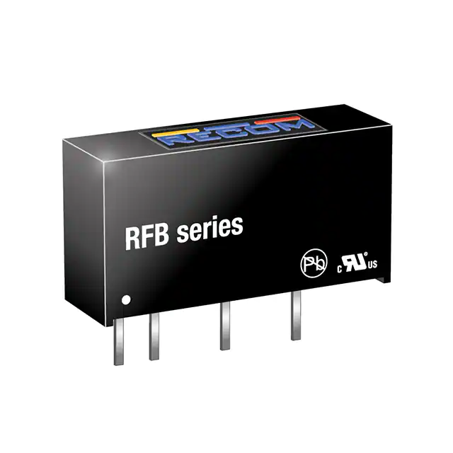
-
RFB-0505S
Recom Power
Tech Hub

Latch circuits retain one bit through feedback. This technical reference covers SR and D latches, truth tables, transparency, timing limits, latch-versus-flip-flop behavior, applications and common log…

An engineering guide to LED driver operation, constant-current and constant-voltage outputs, linear and switching topologies, dimming, IC selection, calculations, replacement compatibility, and fault c…

Operational amplifier guide covering op amp basics, feedback, ideal vs real op amps, common configurations, buffer circuits, offset, bias current, gain-bandwidth, slew rate, rail-to-rail limits and sel…

Jumper cables guide covering safe connection order, red and black clamp placement, final ground connection, cable gauge, length, clamp quality, copper vs CCA cables, jump starter comparison and battery…

LDO regulator guide covering low dropout voltage, power dissipation, thermal design, PSRR, output noise, capacitor stability, adjustable LDO circuits, LDO vs buck converter and datasheet selection chec…

Conditional Access Module guide covering CAM meaning, CI/CI+ interface, smart card authorization, DVB security workflow, TV and set-top box compatibility, internal electronics, ESD protection, connecto…

Guide to electronic component obsolescence covering EOL risk, PCN/PDN notices, last-time buy planning, replacement options, form-fit-function validation, counterfeit risk and BOM lifecycle management.

18650 battery guide covering lithium-ion cell basics, 3.6V/3.7V voltage, 4.2V charging, mAh and Wh capacity, protected cells, chargers, BMS, series-parallel packs, holders, welding and sourcing checks.…

Hall effect sensor guide covering working principle, linear and digital sensors, Arduino circuits, current sensing, speed detection, automotive applications, A3144 examples, signal filtering and datash…

Product Change Notification guide for electronic components, covering PCN meaning, PCN vs PDN/EOL, common change types, risk levels, form-fit-function review, engineering validation, BOM control, LTB/L…


