
 My Inquiry
 My Account


Analog Devices Inc./Maxim Integrated MAXQ1740-FBX+
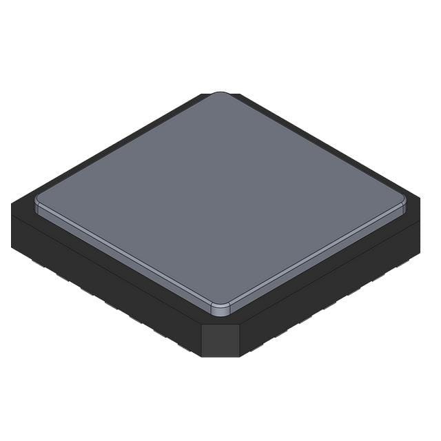
- Part No.:
- MAXQ1740-FBX+
- Manufacturer:
- Analog Devices Inc./Maxim Integrated
- Category:
- Microcontrollers
- Package:
- 28-WFQFN Exposed Pad
- Datasheet:
-
 MAXQ1740-FBX+.pdf
- Description:
- MAGNETIC CARD READER MCU
- Quantity:
- Payment:

- Shipping:

Inventory:2,988
Please send an inquiry. Send us your inquiry, and we will respond immediately.
Product details
Overview
MAXQ1740-FBX+ from Maxim Integrated is a DeepCover® secure microcontroller designed for integration directly into magnetic card reader heads, featuring a 16-bit MAXQ20C RISC CPU, hardware AES encryption engine, true random-number generator, self-destruct input, and triple-track magnetic stripe interface. It operates from 1.7V to 3.6V, includes 16KB flash and 1KB fast-wipe NV SRAM, and targets tamper-resistant ATM/POS terminals.
For engineers reviewing the MAXQ1740-FBX+ datasheet, MAXQ1740-FBX+ pinout, MAXQ1740-FBX+ application, or MAXQ1740-FBX+ equivalent, key selection criteria include tamper-responsive memory zeroization, ISO 7811/7812/7813 magnetic track support, 3µA stop-mode current, 1-Wire debug interface, and 28-pin TQFN-EP package compatibility with secure physical layout requirements.
Technical Context
The MAXQ1740-FBX+ implements a Harvard-architecture MAXQ20C core with 1MIPS/MHz performance, pipelined execution, and orthogonal 16-bit instruction set optimized for C compilation. Its security architecture couples voltage-attack sensors, supply overvoltage detection, and a dedicated self-destruct input to trigger instantaneous zeroization of 128 bytes of AES-working NV SRAM and full wipe of 1KB fast-wipe NV SRAM.
Peripherals are hardened for magnetic card reading: the triple-track interface supports direct connection to 3-track read heads without external signal conditioning; two SPI ports, I²C, USART, and 1-Wire enable secure host communication and in-system programming; dual 16-bit timers and wake-up timer support low-power polling and event timing in battery-powered readers.
Key Specifications
| Parameter | Value and Actual Design Meaning |
|---|---|
| CPU Core | 16-bit MAXQ20C RISC, Harvard architecture, 1MIPS/MHz, pipelined, C-compiler optimized |
| Operating Voltage | 1.7V–3.6V - enables direct use with coin-cell or single Li-ion battery power rails |
| Flash Memory | 16KB - stores user firmware and static data with 512-byte page sectors and 1000 erase/write cycles |
| Secure RAM | 1KB fast-wipe NV SRAM + 128B instantaneous zeroization NV SRAM - wiped on tamper or voltage fault before software access |
| Low-Power Stop Mode | 3µA - maintains tamper-detection circuitry only; exit via GPIO or serial interface activity |
| Clock Sources | 6MHz internal oscillator (±10%) + up to 12MHz external crystal - supports precise timing for magnetic track decoding |
| Security Peripherals | AES hardware accelerator, true RNG, self-destruct input, code scrambling, supply overvoltage detection - meets physical tamper-resistance requirements for payment terminals |
Pinout & Package
MAXQ1740-FBX+ is housed in a 28-pin Thin Quad Flat No-lead Exposed Pad (TQFN-EP) package, RoHS-compliant, with thermal pad for enhanced heat dissipation in compact card-reader enclosures.
| Pin/Terminal | Circuit Role | Design Meaning |
|---|---|---|
| VDD | Power supply input | 1.7V–3.6V main supply; powers all digital and analog blocks except isolated tamper-sensing circuitry |
| GND | Ground reference | Common return for digital, analog, and I/O; requires low-impedance connection to exposed pad |
| SDI | Magnetic stripe data input | Differential input for Track 1/2/3 analog signals; connects directly to magnetic head outputs |
| SDO | Magnetic stripe data output | Output for processed track data after analog front-end and digitization |
| SDCLK | Magnetic stripe clock output | Provides synchronous clock to magnetic head; enables precise bit-rate alignment per ISO standard |
| SCL / SDA | I²C bus interface | Standard bidirectional I²C interface for host communication and configuration |
| SPICLK / SPIMOSI / SPIMISO / SPISSEL | SPI interface signals | Two independent hardware SPI ports support daisy-chained peripherals or secure host offload |
| TXD / RXD | USART interface | Full-duplex asynchronous/synchronous serial interface for encrypted data transmission to host controller |
| 1WIRE | 1-Wire debug port | Single-pin interface for flash programming, debugging, and boundary scan without additional pins |
| SDIN | Self-destruct input | Active-low tamper-detection pin; triggers immediate zeroization of secure RAM and disables further operation |
| GPIO0–GPIO15 | General-purpose I/O | Up to 16 configurable pins; support external interrupt, wake-up, LED control, or sensor interfacing |
Key Features
| Feature | Design Value |
|---|---|
| Tamper-responsive memory wipe | 128B NV SRAM zeroizes instantly on SDIN assertion; 1KB NV SRAM erased before firmware execution begins |
| Triple-track magnetic interface | Direct analog connection to 3-track magnetic heads with integrated clock generation and digitization - eliminates external ADC or timing ICs |
| Hardware AES acceleration | Dedicated engine performs AES-128/192/256 encryption/decryption without CPU intervention - preserves real-time track processing |
| Ultra-low-power stop mode | 3µA quiescent current with active tamper monitoring - extends battery life in portable card readers beyond 5 years |
| 1-Wire debug interface | Single-pin in-circuit programming and debugging - reduces test point count and simplifies PCB layout for security-critical zones |
Applications
| ATM/POS Terminals | Physical Security Access Systems |
|---|---|
Use Scenario: Embedded inside card reader module of unattended kiosk or bank ATM to process magnetic stripe swipes. IC Role / Device Role / Timing Role: Secure front-end processor that reads, decrypts, and validates track data before forwarding to host MCU. Use Value: Prevents skimming by encrypting raw track data at the head-no plaintext exposure in cables or connectors. | Use Scenario: Integrated into door access card readers deployed in corporate offices or government facilities. IC Role / Device Role / Timing Role: Tamper-aware authentication node that verifies card credentials and enforces physical security policies. Use Value: Instantaneous memory wipe on enclosure breach ensures no credential keys or logs persist post-tamper. |
| Payment Terminal Add-On Modules | Secure ID Badge Readers |
Use Scenario: Used as drop-in security upgrade for legacy magstripe terminals lacking embedded encryption. IC Role / Device Role / Timing Role: Standalone cryptographic co-processor interfacing between magnetic head and existing terminal controller. Use Value: Enables PCI PTS v6 compliance without redesigning host hardware-leverages existing SPI/I²C infrastructure. | Use Scenario: Deployed in high-assurance badge readers for data centers or R&D labs requiring FIPS-level credential handling. IC Role / Device Role / Timing Role: Root-of-trust for badge validation, performing on-device AES decryption and RNG-based challenge-response. Use Value: Eliminates need for external secure element; 64-bit factory-programmed serial number enables unique device identity binding. |
Equivalent & Alternatives
The following parts are listed as comparable options for similar secure microcontroller applications.
| Alternative Part | Technical Difference | Application Difference | Selection Advice |
|---|---|---|---|
| MAX32590 | ARM Cortex-M3 core, 256KB flash, no integrated magstripe interface, supports USB and SDIO | Targets broader secure MCU applications (e.g., HSM, secure boot), not magstripe-specific | Select when needing higher compute throughput and peripheral flexibility, but requires external magstripe front-end |
| STM32L4A6VG | ARM Cortex-M4, 1MB flash, no hardware self-destruct input or fast-wipe NV SRAM, AES engine lacks tamper-linked zeroization | General-purpose ultra-low-power MCU; security features require software coordination and lack physical attack response | Select for cost-sensitive designs where full DeepCover-level tamper resistance is not mandated by certification body |
Compared with MAX32590 and STM32L4A6VG, the MAXQ1740-FBX+ uniquely integrates magnetic stripe interface logic, tamper-triggered hardware memory wipe, and ISO-compliant track decoding - making it the only option certified for direct magstripe head placement in PCI PTS v6 Level 3 devices.
Availability
MAXQ1740-FBX+ is available at Aetrix Electronics and suitable for ATM/POS terminals, physical security access systems, and secure ID badge readers requiring stable component supply, long lifecycle support, and traceable sourcing for regulated deployments.
Supply support for MAXQ1740-FBX+ includes scheduled delivery planning, volume procurement assistance, BOM continuity management, traceable sourcing, and lifecycle availability coordination for OEM customers, industrial embedded developers, connected-device designers, and electronics production programs.
Manufacturer
Maxim Integrated, now part of Analog Devices, designs precision analog, mixed-signal, and secure ICs for industrial, automotive, communications, and computing applications.
The MAXQ1740-FBX+ belongs to the DeepCover® secure microcontroller product line, engineered specifically to embed cryptographic protection and physical tamper resistance directly at the point of magnetic card interaction - enabling PCI PTS and FIPS-compliant payment and access systems.
FAQ
What is the primary security function of the self-destruct input on the MAXQ1740-FBX+?
The self-destruct input (SDIN) on the MAXQ1740-FBX+ is an active-low tamper-detection pin that, when asserted, triggers instantaneous zeroization of the 128-byte AES-working NV SRAM and initiates full erasure of the 1KB fast-wipe NV SRAM before any application firmware can execute. This hardware-enforced response prevents extraction of cryptographic keys or sensitive data during physical intrusion attempts, satisfying PCI PTS v6 Level 3 tamper-resistance requirements.
Does the MAXQ1740-FBX+ support all three magnetic stripe tracks simultaneously?
Yes, the MAXQ1740-FBX+ integrates a dedicated triple-track magnetic stripe interface capable of simultaneous analog acquisition and digitization of Tracks 1, 2, and 3. Its SDI, SDO, and SDCLK pins provide direct connection to standard 3-track read heads, and reference firmware supports ISO 7811, ISO 7812, and ISO 7813 formats - enabling full multi-track parsing without external signal conditioning or timing controllers.
What is the role of the 1-Wire interface on the MAXQ1740-FBX+?
The 1-Wire interface on the MAXQ1740-FBX+ serves as a single-pin debug and programming port for in-circuit flash programming, real-time debugging, and boundary-scan testing. It eliminates the need for dedicated JTAG/SWD headers, reducing PCB footprint and simplifying secure layout - especially critical in tamper-resistant enclosures where test points must be minimized or hidden.
How does the MAXQ1740-FBX+ achieve ultra-low power consumption in stop mode?
The MAXQ1740-FBX+ achieves 3µA stop-mode current by powering down the CPU core, flash memory, and most peripherals while retaining only essential tamper-monitoring circuitry - including the self-destruct input detector, voltage-attack sensors, and minimal clock logic. The device remains responsive to wake events from GPIO pins or serial interface activity, enabling rapid resumption of magnetic card reading with sub-millisecond latency.
Is factory programming of secret keys supported for the MAXQ1740-FBX+?
Yes, Maxim Integrated offers optional factory programming of a unique 64-bit serial number and/or customer-defined secret key(s) into the MAXQ1740-FBX+ during wafer sort or final test. This service ensures cryptographic material is injected in a controlled environment prior to shipment, eliminating risks associated with field provisioning and supporting root-of-trust establishment in certified payment and access systems.
MAXQ1740-FBX+ Specifications
- Product attributes
- Attribute value
- Manufacturer:
- Analog Devices Inc./Maxim Integrated
- Package/Case:
- 28-WFQFN Exposed Pad
- Series:
- -
- Packaging:
- Bulk
- Product Status:
- Active
- Programmable:
- Not Verified
- Core Processor:
- MAXQ20C
- Core Size:
- 16-Bit
- Speed:
- 6MHz
- Connectivity:
- I2C, SPI, UART/USART
- Peripherals:
- AES, TRNG, WDT
- Number of I/O:
- 16
- Program Memory Size:
- 16KB (16K x 8)
- Program Memory Type:
- FLASH
- EEPROM Size:
- -
- RAM Size:
- 1K x 8
- Voltage - Supply (Vcc/Vdd):
- 1.7V ~ 3.6V
- Data Converters:
- -
- Oscillator Type:
- Internal
- Operating Temperature:
- 0°C ~ 70°C (TA)
- Grade:
- -
- Qualification:
- -
- Mounting Type:
- Surface Mount
- Supplier Device Package:
MAXQ1740-FBX+ FAQ
1.How can I place an order for MAXQ1740-FBX+ through Aetrix?
Please submit a Request for Quotation (RFQ) for MAXQ1740-FBX+ on Aetrix. Our sales agent will provide a competitive quotation and guide you through the order confirmation once you accept the terms.
2.Are the price and stock information for MAXQ1740-FBX+ reliable?
The price and inventory of MAXQ1740-FBX+ are updated periodically and may fluctuate due to market conditions. Stock and pricing data are typically refreshed every 24 hours. Quotation validity for MAXQ1740-FBX+ is usually 5 days.
3.What payment methods are accepted for MAXQ1740-FBX+?
We accept Wire Transfer, PayPal, Credit Card, Western Union, MoneyGram, and Escrow for MAXQ1740-FBX+ transactions.
Note: Certain payment methods may incur a processing fee.
4.How is shipping managed for MAXQ1740-FBX+?
MAXQ1740-FBX+ orders can be shipped via leading logistics carriers, including DHL, UPS, FedEx, TNT, or Registered Mail.
Once your MAXQ1740-FBX+ order is processed, you will receive an email with the shipment details and tracking number.
Note: Tracking information may take up to 24 hours to appear. Express delivery typically takes 3–5 business days.
5.How can I obtain technical support or documentation for MAXQ1740-FBX+?
For technical support, including MAXQ1740-FBX+ datasheets, pinout diagrams, or application guidance, please contact our engineering support team. They can provide detailed documentation and assistance for your MAXQ1740-FBX+ requirements.
6.How does Aetrix verify that MAXQ1740-FBX+ is sourced from the original manufacturer or authorized distributors?
All MAXQ1740-FBX+ products on Aetrix are procured from qualified distributors and authorized channels. Our dedicated quality assurance team conducts strict verification, including traceability checks and, if necessary, third-party testing. This ensures that MAXQ1740-FBX+ meets industry standards.
7.What is the process for return or replacement of MAXQ1740-FBX+?
All MAXQ1740-FBX+ units undergo pre-shipment inspection (PSI). If there is an issue with MAXQ1740-FBX+, returns or replacements are accepted under the following conditions:
1.Quantity discrepancies, incorrect items, or visible external defects (such as breakage or corrosion), acknowledged by Aetrix.
2.The issue is reported within 90 days of delivery.
3.The MAXQ1740-FBX+ part is unused and in its original packaging.
Return procedure for MAXQ1740-FBX+:
1.Submit a request within 90 days.
2.Obtain a Return Material Authorization (RMA) from Aetrix.
MAXQ1740-FBX+ Tags

-
ATTINY4-TSHR
Microchip Technology
-
ATTINY10-TSHR
Microchip Technology
-
ATTINY10-TS8R
Microchip Technology

-
ATTINY202-SSNR
Microchip Technology
-
ATTINY202-SSFR
Microchip Technology
-
ATTINY402-SSNR
Microchip Technology

-
PIC16F15213T-I/MF
Microchip Technology
-
PIC16F15213-E/MF
Microchip Technology

-
PIC10F200T-I/OT
Microchip Technology
-
ATTINY412-SSNR
Microchip Technology
-
PIC10F202T-I/OT
Microchip Technology

-
ATTINY404-SSNR
Microchip Technology
Tech Hub

A practical engineering guide to 3.3V and 5V logic compatibility, input thresholds, resistor dividers, translator ICs, MOSFET level shifting, I2C pull-ups, timing limits and power-sequencing risks.

The 74HC595 uses push-pull logic outputs, while the TPIC6B595 uses 50 V open-drain DMOS sinks for higher-power loads. This guide compares timing, current limits, 3.3 V interfacing, load wiring, thermal…

The 74HC595 converts serial data into eight stable parallel outputs. This guide covers pin functions, shift and storage timing, OE and MR behavior, drive-current limits, cascading, voltage compatibilit…

A technical comparison of level-sensitive latches and edge-triggered flip-flops, covering timing windows, setup and hold limits, master–slave operation, time borrowing, race-through, HDL inference and…

A D latch stores one bit while Enable controls when data can pass. This reference covers gate-level operation, truth tables, transparency, setup and hold timing, LE versus OE, common ICs and practical …

An SR latch stores one bit through cross-coupled feedback. This engineering reference covers NOR and NAND implementations, truth tables, forbidden-state recovery, gated operation, switch debouncing, fa…

Latch circuits retain one bit through feedback. This technical reference covers SR and D latches, truth tables, transparency, timing limits, latch-versus-flip-flop behavior, applications and common log…

An engineering guide to LED driver operation, constant-current and constant-voltage outputs, linear and switching topologies, dimming, IC selection, calculations, replacement compatibility, and fault c…

Operational amplifier guide covering op amp basics, feedback, ideal vs real op amps, common configurations, buffer circuits, offset, bias current, gain-bandwidth, slew rate, rail-to-rail limits and sel…

Jumper cables guide covering safe connection order, red and black clamp placement, final ground connection, cable gauge, length, clamp quality, copper vs CCA cables, jump starter comparison and battery…


