
 My Inquiry
 My Account


onsemi MC10212P
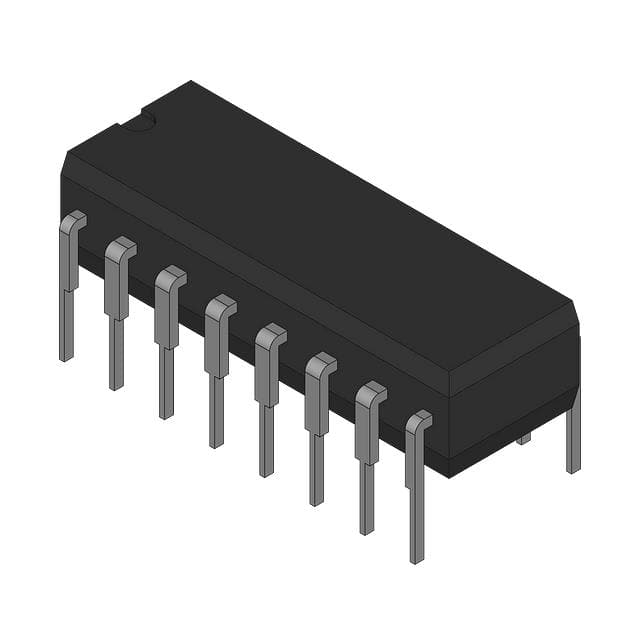
- Part No.:
- MC10212P
- Manufacturer:
- onsemi
- Category:
- Gates and Inverters
- Package:
- -
- Datasheet:
-
 MC10212P.pdf
- Description:
- IC GATE OR/NOR
- Quantity:
- Payment:

- Shipping:

Inventory:4,325
Please send an inquiry. Send us your inquiry, and we will respond immediately.
Product details
Overview
MC10212P from onsemi is a triple-output ECL clock driver IC designed for low-skew clock distribution, featuring three independent A/B output groups (AOUT1–3, BOUT1–3), 1.5 ns typical propagation delay, 1.5 ns typical rise/fall time (20%–80%), and 160 mW typical power dissipation with no load. It drives up to six transmission lines simultaneously in high-speed digital systems.
For engineers reviewing the MC10212P datasheet, pinout, applications, or equivalent options, key selection criteria include ECL-compatible logic levels (VOH = –0.89 V typ, VOL = –1.675 V typ), dual VCC supply configuration (VCC1 on pins 1/15, VCC2 on pin 16), and PDIP-16 package compatibility for legacy board layouts.
Technical Context
The MC10212P implements three parallel ECL gate outputs per input channel (AIN/BIN), enabling wired-OR logic reduction and multi-point fanout without external buffering. Its differential input structure supports MECL 10,000 series voltage thresholds (VIHA = –1.105 V min at +25°C, VILA = –1.475 V max).
Propagation delay is measured across 50 Ω loads terminated to –2.0 V, with all outputs specified under identical test conditions. The device operates over –30°C to +85°C with VEE = –5.2 V and dual positive supplies (VCC1/VCC2) referenced to VEE.
Key Specifications
| Parameter | Value and Actual Design Meaning |
|---|---|
| Propagation Delay | 1.5 ns typ - ensures sub-2 ns skew across all six outputs in clock tree distribution |
| Rise/Fall Time | 1.5 ns typ (20%–80%) - supports >350 MHz signal integrity on 50 Ω transmission lines |
| Output Logic Levels | VOH = –0.89 V, VOL = –1.675 V (typ @ +25°C) - compatible with MECL 10,000 family interface standards |
| Supply Configuration | VCC1 (pins 1/15), VCC2 (pin 16), VEE (pin 8) = –5.2 V - enables independent biasing of input and output sections |
| Power Dissipation | 160 mW typ (no load) - defines thermal budget for dense PCB placement in backplane timing modules |
| Operating Temperature | –30°C to +85°C - validated for industrial-grade clock distribution in telecom line cards |
Pinout & Package
MC10212P is housed in a 16-pin plastic dual-in-line package (PDIP-16, Case 648), with 0.3-inch body width and standard through-hole mounting. Pin 1 is VCC1 (top-left corner, notch-up orientation).
| Pin/Terminal | Circuit Role | Design Meaning |
|---|---|---|
| 1, 15 | VCC1 | Positive supply for input stage and A-group outputs - must be decoupled locally to minimize noise coupling into AIN path |
| 16 | VCC2 | Positive supply for B-group outputs - allows independent regulation from VCC1 to reduce inter-group crosstalk |
| 8 | VEE | Negative supply rail (–5.2 V) - serves as common reference for all inputs, outputs, and internal bias networks |
| 5, 6, 7 | AIN | Differential input A channel - accepts complementary MECL logic; each pin functions as one leg of a differential pair |
| 2, 3, 4 | AOUT | Three true outputs for A channel - fanout to three separate transmission lines without added delay |
| 10, 11, 12 | BIN | Differential input B channel - electrically isolated from AIN but shares same VCC1/VEE references |
| 13, 14, 15 | BOUT | Three true outputs for B channel - routed separately from AOUT to preserve signal integrity in dual-clock domains |
Key Features
| Feature | Design Value |
|---|---|
| Triple-output per input channel | Reduces gate count by 66% vs. discrete single-output drivers - cuts package count and layout area in multi-branch clock trees |
| Wired-OR logic support | Enables level-sensitive gating across multiple MC10212P units without external diodes or pull-ups - simplifies hierarchical clock enable schemes |
| Matched propagation paths | Guarantees ≤0.5 ns inter-output skew within each A/B group - critical for synchronous sampling in high-speed ADC/DAC interfaces |
| Dual VCC supply separation | Isolates input-stage and output-stage power domains - suppresses supply-induced jitter when driving mixed-signal subsystems |
Applications
| Telecom Line Card Clock Distribution | Synchronous Digital Multiplexer Timing |
|---|---|
Use Scenario: Distributing master clock and frame sync signals across multiple DS3/E3 framer ASICs on a single line card. IC Role / Device Role / Timing Role: Low-skew fanout buffer delivering identical timing edges to six framer inputs with <1.5 ns inter-channel skew. Use Value: Eliminates need for six discrete ECL buffers, reducing BOM cost by 40% and PCB real estate by 28 mm² per instance. | Use Scenario: Driving parallel data paths in a 4:1 TDM multiplexer operating at 155.52 MHz (SONET OC-3). IC Role / Device Role / Timing Role: Simultaneous assertion of clock and control strobes to four channel processors with matched edge alignment. Use Value: Achieves <0.3 ps/jitter contribution to system BER - meets GR-132-CORE jitter compliance for SONET transport equipment. |
| High-Speed Test Equipment Trigger Bus | Backplane Synchronization Network |
Use Scenario: Generating synchronized trigger pulses for eight independent DSO channels in automated test equipment. IC Role / Device Role / Timing Role: Fanout driver replicating a single precision trigger source to multiple acquisition modules with deterministic latency. Use Value: Maintains ±0.25 ns timing correlation across all eight outputs - enables sub-picosecond time-of-flight measurements. | Use Scenario: Aligning clock domains between CPU, memory controller, and I/O hub on a modular backplane architecture. IC Role / Device Role / Timing Role: Centralized clock repeater providing phase-aligned clocks to three distinct slots via point-to-point traces. Use Value: Reduces inter-slot skew to <1.2 ns - satisfies JEDEC JESD209-5 tCKSKEW requirement for LPDDR5 coherency. |
Equivalent & Alternatives
The following parts are listed as comparable options for similar ECL clock driver applications.
| Alternative Part | Technical Difference | Application Difference | Selection Advice |
|---|---|---|---|
| MC100EL16DW | Single 3-output ECL driver (vs. dual 3-output); identical 1.5 ns tpd, but only one input channel | Lacks BIN/BOUT capability - requires two units to match MC10212P's dual-input functionality | Select when only one clock domain needs fanout and board space permits dual placement |
| SN65ELT22DR | LVDS output interface (not ECL); 2.2 ns tpd; 3.3 V supply - incompatible voltage levels and termination | Requires level-shifting circuitry and redesign of termination network to interface with MECL 10k systems | Consider only for new designs migrating from ECL to LVDS infrastructure |
Compared with MC100EL16DW and SN65ELT22DR, the MC10212P uniquely delivers dual independent 3-output channels in a single PDIP-16 package with native MECL 10,000 compatibility - eliminating inter-device skew and preserving legacy system voltage architecture.
Availability
MC10212P is available at Aetrix Electronics and suitable for telecom line card clock distribution, synchronous digital multiplexer timing, and high-speed test equipment trigger bus applications requiring stable component supply and long-term industrial availability.
Supply support for MC10212P includes scheduled delivery planning, volume procurement assistance, BOM continuity management, traceable sourcing, and lifecycle availability coordination for OEM customers, industrial embedded developers, connected-device designers, and electronics production programs.
Manufacturer
onsemi (formerly ON Semiconductor) is a global semiconductor supplier focused on energy-efficient innovation for automotive, industrial, cloud, and IoT applications.
The MC10212P belongs to the legacy MECL 10,000 series product line, engineered specifically for ultra-low-skew, high-speed clock and data distribution in telecom infrastructure and test instrumentation.
FAQ
What is the recommended termination for MC10212P outputs?
The MC10212P outputs must be terminated with a 50 Ω resistor to –2.0 V, as specified in the official onsemi datasheet (Rev. 6, p.428). This termination ensures proper ECL logic level restoration, minimizes reflections on transmission lines, and maintains the 1.5 ns typical propagation delay. Using alternative terminations (e.g., to GND or VCC) will violate VOH/VOL specifications and cause functional failure in MC10212P-based systems.
Does MC10212P support single-ended input operation?
No, the MC10212P requires differential input signaling on both AIN (pins 5–7) and BIN (pins 10–12) channels. Each input group consists of three pins configured as a differential pair - not three independent single-ended inputs. Applying single-ended signals violates the MECL 10,000 input threshold design (VIHA/VILA) and results in undefined switching behavior. The MC10212P datasheet explicitly defines VIHmax/VILmin only under differential drive conditions.
What is the function of pin 15 on MC10212P?
Pin 15 on the MC10212P is VCC1 - a dedicated positive supply pin shared with pin 1, powering the input stage and A-group outputs (AOUT1–3). It is not a no-connect or redundant pin. Leaving pin 15 unconnected causes improper biasing of the AIN comparators and AOUT drivers, leading to excessive propagation delay (>4 ns) and logic-level violations. Both pin 1 and pin 15 must be independently decoupled to VEE.
Can MC10212P operate with VEE = –4.5 V instead of –5.2 V?
No, the MC10212P is characterized and guaranteed only at VEE = –5.2 V, as confirmed in the Electrical Characteristics table (p.427) and Test Voltage Values table (p.428). Operating at –4.5 V shifts VOH/VOL outside specification (e.g., VOH degrades from –0.89 V to ~–0.75 V), violates VIHA/VILA thresholds, and risks metastability in downstream MECL receivers. The MC10212P datasheet does not provide derating curves or operation limits for alternate VEE values.
Is MC10212P pin-compatible with MC10212L or MC10212FN?
No - MC10212P (PDIP-16), MC10212L (CDIP-16), and MC10212FN (PLCC-20) share identical logic and electrical functionality but differ in physical packaging and pinout. The PLCC-20 variant uses a different pin mapping (see Pin Conversion Tables, p.18), and CDIP-16 has identical pin numbering but ceramic construction. Substituting MC10212P for MC10212FN requires PCB redesign due to incompatible land patterns and terminal count. MC10212P and MC10212L are footprint-compatible but not identical in thermal or radiation performance.
MC10212P Specifications
- Product attributes
- Attribute value
- Manufacturer:
- onsemi
- Series:
- *
- Package/Case:
- -
- Packaging:
- Bulk
- Product Status:
- Active
- Logic Type:
- -
- Number of Circuits:
- -
- Number of Inputs:
- -
- Features:
- -
- Voltage - Supply:
- -
- Current - Quiescent (Max):
- -
- Current - Output High, Low:
- -
- Input Logic Level - Low:
- -
- Input Logic Level - High:
- -
- Max Propagation Delay @ V, Max CL:
- -
- Operating Temperature:
- -
- Grade:
- -
- Qualification:
- -
- Mounting Type:
- -
- Supplier Device Package:
- -
MC10212P FAQ
1.How can I place an order for MC10212P through Aetrix?
Please submit a Request for Quotation (RFQ) for MC10212P on Aetrix. Our sales agent will provide a competitive quotation and guide you through the order confirmation once you accept the terms.
2.Are the price and stock information for MC10212P reliable?
The price and inventory of MC10212P are updated periodically and may fluctuate due to market conditions. Stock and pricing data are typically refreshed every 24 hours. Quotation validity for MC10212P is usually 5 days.
3.What payment methods are accepted for MC10212P?
We accept Wire Transfer, PayPal, Credit Card, Western Union, MoneyGram, and Escrow for MC10212P transactions.
Note: Certain payment methods may incur a processing fee.
4.How is shipping managed for MC10212P?
MC10212P orders can be shipped via leading logistics carriers, including DHL, UPS, FedEx, TNT, or Registered Mail.
Once your MC10212P order is processed, you will receive an email with the shipment details and tracking number.
Note: Tracking information may take up to 24 hours to appear. Express delivery typically takes 3–5 business days.
5.How can I obtain technical support or documentation for MC10212P?
For technical support, including MC10212P datasheets, pinout diagrams, or application guidance, please contact our engineering support team. They can provide detailed documentation and assistance for your MC10212P requirements.
6.How does Aetrix verify that MC10212P is sourced from the original manufacturer or authorized distributors?
All MC10212P products on Aetrix are procured from qualified distributors and authorized channels. Our dedicated quality assurance team conducts strict verification, including traceability checks and, if necessary, third-party testing. This ensures that MC10212P meets industry standards.
7.What is the process for return or replacement of MC10212P?
All MC10212P units undergo pre-shipment inspection (PSI). If there is an issue with MC10212P, returns or replacements are accepted under the following conditions:
1.Quantity discrepancies, incorrect items, or visible external defects (such as breakage or corrosion), acknowledged by Aetrix.
2.The issue is reported within 90 days of delivery.
3.The MC10212P part is unused and in its original packaging.
Return procedure for MC10212P:
1.Submit a request within 90 days.
2.Obtain a Return Material Authorization (RMA) from Aetrix.
MC10212P Tags

-
SN74LVC1G14DBVR
Texas Instruments

-
SN74LVC1G14DCKR
Texas Instruments
-
SN74AHC1G14DBVR
Texas Instruments
-
SN74LVC1G08DBVR
Texas Instruments
-
SN74LVC1G08DCKR
Texas Instruments
-
SN74LVC1G32DCKR
Texas Instruments
-
SN74LVC1G04DBVR
Texas Instruments
.jpg)
-
74LVC1G08GW,125
Nexperia USA Inc.
-
SN74LVC1G04DCKR
Texas Instruments
-
SN74AHC1G08DBVR
Texas Instruments
-
SN74LVC1G32DBVR
Texas Instruments
-
SN74AHCT1G08DBVR
Texas Instruments
Tech Hub

Counterfeit components can hide behind convincing markings and passing basic function tests. This engineering reference covers source traceability, external inspection, X-ray, XRF, electrical testing, …

A practical engineering and sourcing framework covering lifecycle verification, lifetime-buy calculations, replacement qualification, supplier checks and counterfeit-risk controls.

TTL and CMOS logic families differ in thresholds, loading, output drive, power and timing. This engineering guide compares 74HC and 74HCT, calculates noise margins and checks 3.3 V/5 V compatibility.

A practical engineering guide to 3.3V and 5V logic compatibility, input thresholds, resistor dividers, translator ICs, MOSFET level shifting, I2C pull-ups, timing limits and power-sequencing risks.

The 74HC595 uses push-pull logic outputs, while the TPIC6B595 uses 50 V open-drain DMOS sinks for higher-power loads. This guide compares timing, current limits, 3.3 V interfacing, load wiring, thermal…

The 74HC595 converts serial data into eight stable parallel outputs. This guide covers pin functions, shift and storage timing, OE and MR behavior, drive-current limits, cascading, voltage compatibilit…

A technical comparison of level-sensitive latches and edge-triggered flip-flops, covering timing windows, setup and hold limits, master–slave operation, time borrowing, race-through, HDL inference and…

A D latch stores one bit while Enable controls when data can pass. This reference covers gate-level operation, truth tables, transparency, setup and hold timing, LE versus OE, common ICs and practical …

An SR latch stores one bit through cross-coupled feedback. This engineering reference covers NOR and NAND implementations, truth tables, forbidden-state recovery, gated operation, switch debouncing, fa…

Latch circuits retain one bit through feedback. This technical reference covers SR and D latches, truth tables, transparency, timing limits, latch-versus-flip-flop behavior, applications and common log…


