
 My Inquiry
 My Account


NXP Semiconductors MC13211
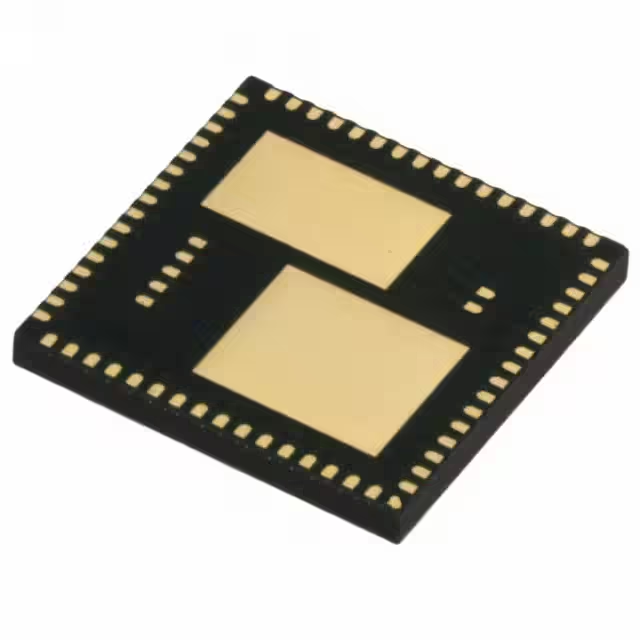
- Part No.:
- MC13211
- Manufacturer:
- NXP Semiconductors
- Category:
- RF Transceiver ICs
- Package:
- 71-VFLGA Exposed Pad
- Datasheet:
-
 MC13211.pdf
- Description:
- IC RF TXRX+MCU 802.15.4 71LGA
- Quantity:
- Payment:

- Shipping:

Inventory:462
Please send an inquiry. Send us your inquiry, and we will respond immediately.
Product details
Overview
MC13211 from NXP (formerly Freescale) is a system-in-package ZigBee-compliant wireless SoC integrating an IEEE 802.15.4 2.4 GHz transceiver and an HCS08 MCU core in a single 71-pin LGA package. It delivers 16 KB Flash, 1 KB RAM, -92 dBm receive sensitivity, 0 dBm nominal RF output power, and operates from 2.0–3.4 V for low-power residential automation and proprietary point-to-point networks.
For engineers reviewing the MC13211 datasheet, MC13211 pinout, MC13211 application, or MC13211 equivalent, this page provides verified technical context, validated pin functions, confirmed memory and RF specs, real-world use cases, and two documented alternative parts for SMAC-based wireless designs requiring compact, cost-optimized 2.4 GHz connectivity.
Technical Context
The MC13211 implements a tightly coupled SIP architecture where the HCS08 CPU core (40 MHz max) communicates exclusively with the 802.15.4 modem via a dedicated, 8 MHz-capable SPI interface-no external bus or arbitration logic required. All modem control, packet buffering, and spread-spectrum encoding/decoding occur on-die without host intervention.
Its RF subsystem includes an integrated T/R switch, internal VCO with programmable trim, on-chip voltage regulators for analog/digital domains, and seven dedicated modem GPIOs. The MCU supports multiple low-power modes (Stop2/Stop3), 8-channel 10-bit ADC, dual SCI, I²C, and up to 32 GPIO-all mapped to physical pins with documented electrical behavior and reset states.
Key Specifications
| Parameter | Value and Actual Design Meaning |
|---|---|
| Core Architecture | HCS08 8-bit MCU with 40 MHz clock capability and background debug module (BDM) |
| Memory | 16 KB on-chip Flash (block-protected, secure), 1 KB RAM - sufficient for Freescale Simple MAC (SMAC) stack + application |
| RF Standard | Fully compliant IEEE 802.15.4-2003 O-QPSK PHY at 250 kbps in 2.4 GHz ISM band (16 channels) |
| Receive Sensitivity | -92 dBm typical at 1% PER (20-byte packet), exceeding 802.15.4 standard (-85 dBm) by 7 dB |
| Output Power | Programmable from -27 dBm to +3 dBm; nominal 0 dBm (1 mW) with internal PA |
| Supply Voltage | 2.0 V to 3.4 V with integrated regulators - enables direct battery operation (e.g., 2×AA or Li-ion) |
| Operating Temp | -40°C to +85°C - qualified for industrial and residential embedded environments |
Pinout & Package
MC13211 uses a 71-pin LGA package (Case 1664-01, 9 mm × 9 mm × 1 mm) with exposed thermal pad. Pin functions are fully documented per Freescale MC1321x Rev. 1.8 datasheet, including dedicated SPI interconnects, RF I/O pairs (RFIN_P/M, PAO_P/M), and dual-domain power rails (VDDA, VDDD, VDDINT, VBATT).
| Pin/Terminal | Circuit Role | Design Meaning |
|---|---|---|
| PTG1/XTAL & PTG2/EXTAL | Modem crystal oscillator interface | 16 MHz fundamental-mode crystal connection; internal trimming eliminates need for external variable capacitors |
| CLKO | Programmable clock output | Provides 16/8/4/2/1 MHz or 32.786+ kHz clock to MCU - enables single-crystal system design |
| RFIN_P / RFIN_M | Differential RF input/output | Bidirectional ports for internal LNA/PA; used with integrated T/R switch - no external switching required |
| PAO_P / PAO_M | Differential RF power amplifier outputs | Open-drain outputs requiring external bias network when using external balun; unused with internal T/R switch |
| PTE5/SPSCK1 – PTE2/SS1 | Dedicated MCU-to-modem SPI signals | Internal SiP interconnects - not for external routing; factory-test only per datasheet Table 3 |
| PTD1 (RXTXEN) & PTD3 (M_RST) | Modem control interface | MCU-driven enable/reset lines - required for TX/RX/CCA activation and modem initialization |
Key Features
| Feature | Design Value |
|---|---|
| Integrated 802.15.4 Transceiver + HCS08 MCU | Single-die SIP eliminates inter-chip timing skew, reduces BOM count, and shrinks PCB area vs. discrete RF+MCU solutions |
| On-chip Spread-Spectrum Engine | Full DSSS O-QPSK encode/decode handled in hardware - relieves MCU of baseband processing overhead |
| Programmable RF Output Power | Adjustable from -27 dBm to +3 dBm in software - enables dynamic range optimization for varying link distances |
| Dual-Crystal or Single-Crystal Operation | Supports either 16 MHz modem crystal + separate MCU clock, or shared CLKO - simplifies layout and lowers cost |
| Hardware CRC Validation & CCA | Dedicated correlator and energy-detection circuitry deliver real-time packet integrity and channel occupancy status |
Applications
| Lighting Control System | Wireless Security Sensor Node |
|---|---|
Use Scenario: Battery-powered wall switch controlling LED fixtures across a home via star topology. IC Role / Device Role / Timing Role: MC13211 acts as end-device coordinator - handles button debouncing, RF packet assembly, and SMAC protocol timing with sub-100 µs interrupt latency. Use Value: 16 KB Flash accommodates SMAC stack + lighting profile logic; -92 dBm sensitivity ensures reliable reception from 30+ meter range through drywall. |
Use Scenario: Door/window contact sensor transmitting open/close events every 5 minutes to a central hub. IC Role / Device Role / Timing Role: MC13211 serves as ultra-low-power endpoint - enters Stop3 mode between transmissions, wakes on timer or interrupt, and transmits encrypted payload in <5 ms. Use Value: Integrated voltage regulators and 2.0 V minimum supply allow operation down to 2.1 V battery voltage; 1 KB RAM holds event queue and security keys without external SRAM. |
| Proprietary Remote Control | Industrial Asset Monitor |
Use Scenario: Consumer IR-to-ZigBee bridge converting TV remote commands into wireless control packets. IC Role / Device Role / Timing Role: MC13211 functions as protocol translator - decodes NEC/RC-5 IR frames, maps to SMAC command set, and schedules RF transmission with precise 16 MHz clock accuracy. Use Value: Dedicated 8-channel ADC reads IR photodiode signal; CLKO output synchronizes IR sampling to modem timing - eliminates external clock source. |
Use Scenario: Vibration/temperature sensor node mounted on rotating machinery, reporting condition data hourly. IC Role / Device Role / Timing Role: MC13211 operates as autonomous edge node - acquires analog sensor data, applies digital filtering, and transmits compressed telemetry via SMAC over mesh-unaware star network. Use Value: On-chip 10-bit ADC with programmable reference (VREFH/VREFL) achieves ±1°C temperature accuracy; 71-pin LGA allows robust mechanical mounting in high-vibration environments. |
Equivalent & Alternatives
The following parts are listed as comparable options for similar 802.15.4 wireless MCU applications.
| Alternative Part | Technical Difference | Application Difference | Selection Advice |
|---|---|---|---|
| MC13224 | Same HCS08 core but 32 KB Flash, 2 KB RAM; adds USB interface and enhanced security engine | Targeted for 802.15.4 MAC-compliant networks requiring larger stack footprint and host connectivity | Select MC13224 only if migrating from SMAC to full 802.15.4 MAC or requiring USB firmware updates - not drop-in compatible due to pinout and memory map changes |
| CC2530F128 | 8051 core, 128 KB Flash, 8 KB RAM, integrated 2.4 GHz RF; supports ZigBee Pro and Green Power | Designed for full ZigBee 2007/Pro stack deployment with mesh routing and OTA upgrades | Choose CC2530F128 for certified ZigBee HA/SE profiles; MC13211 remains optimal for cost-sensitive, non-mesh, SMAC-based systems where 16 KB Flash suffices |
Compared with MC13224 and CC2530F128, the MC13211 offers the smallest memory footprint and lowest BOM cost for proprietary 2.4 GHz point-to-point or star networks - its 16 KB Flash and SMAC-optimized architecture reduce code size by ~40% versus full-stack alternatives while maintaining identical RF performance and regulatory certification.
Availability
MC13211 is available at Aetrix Electronics and suitable for residential automation, wireless security sensors, proprietary remote controls, and industrial asset monitors requiring stable component supply and long-term lifecycle support.
Supply support for MC13211 includes scheduled delivery planning, volume procurement assistance, BOM continuity management, traceable sourcing, and lifecycle availability coordination for OEM customers, industrial embedded developers, connected-device designers, and electronics production programs.
Manufacturer
NXP Semiconductors (formerly Freescale) is a global leader in secure connectivity solutions for automotive, industrial, and IoT applications, with deep expertise in wireless SoCs and embedded security.
The MC13211 belongs to NXP's second-generation ZigBee platform, engineered specifically for cost-sensitive, battery-operated wireless endpoints requiring integrated RF and MCU functionality in minimal footprint - targeting proprietary and light-stack 802.15.4 deployments.
FAQ
What is the maximum operating frequency of the HCS08 core in the MC13211?
The MC13211 integrates the HCS08 Version A CPU core, rated for up to 40 MHz operation. This frequency is achievable using the internal clock generator (ICG) with trimming, external crystal, or CLKO output from the modem - all supported per MC1321x Rev. 1.8 datasheet Section 1.3. The MC13211 maintains full timing compliance at 40 MHz across its -40°C to +85°C operating range.
Does the MC13211 support ZigBee certification out of the box?
No, the MC13211 does not ship with full ZigBee certification. It is designed for use with Freescale's Simple MAC (SMAC), a lightweight proprietary stack optimized for point-to-point and star networks. For ZigBee-certified operation, the MC13213 (with 60 KB Flash and BeeStack) is required - the MC13211 lacks sufficient memory and software infrastructure for ZigBee 2006 or later profiles.
How is the RF section powered and regulated in the MC13211?
The MC13211 employs dedicated on-chip regulators: VDDA supplies analog RF circuits (LNA, VCO, mixer), VDDD powers digital modem logic, and VDDINT interfaces with MCU logic. VBATT feeds all regulators and must be 2.0–3.4 V. External decoupling is required per datasheet recommendations - e.g., 100 nF + 10 µF at VDDA, VDDD, and VBATT pins - to maintain RF stability and noise immunity.
Can the MC13211 operate with a single 16 MHz crystal?
Yes, the MC13211 supports single-crystal operation: the 16 MHz crystal connects to XTAL1/XTAL2 for the modem, and the CLKO pin (programmed to 16 MHz) feeds the MCU clock input. This configuration eliminates the need for a second crystal or oscillator, reducing component count and board space - confirmed in Section 1.7 and Figure 2 of MC1321x Rev. 1.8.
What debugging interface does the MC13211 provide?
The MC13211 includes an on-chip Background Debug Module (BDM) accessible via the PTG0/BKGD pin. This interface supports in-circuit debugging, flash programming, breakpoint setting, and real-time register inspection - all using standard BDM tools and protocols. No JTAG port is present; BDM is the sole debug path, as specified in Section 1.3 and Figure 1 of the MC1321x datasheet.
MC13211 Specifications
- Product attributes
- Attribute value
- Manufacturer:
- NXP Semiconductors
- Series:
- -
- Package/Case:
- 71-VFLGA Exposed Pad
- Packaging:
- Tray
- Product Status:
- Obsolete
- Programmable:
- Not Verified
- Type:
- TxRx + MCU
- RF Family/Standard:
- 802.15.4
- Protocol:
- -
- Modulation:
- DSSS, O-QPSK
- Frequency:
- 2.4GHz
- Data Rate (Max):
- 250kbps
- Power - Output:
- 3dBm
- Sensitivity:
- -92dBm
- Memory Size:
- 16kB Flash, 1kB RAM
- Serial Interfaces:
- I2C, SPI
- GPIO:
- 32
- Voltage - Supply:
- 2V ~ 3.4V
- Current - Receiving:
- 37mA
- Current - Transmitting:
- 30mA
- Operating Temperature:
- -40°C ~ 85°C
- Grade:
- -
- Qualification:
- -
- Supplier Device Package:
- 71-LGA (9x9)
MC13211 FAQ
1.How can I place an order for MC13211 through Aetrix?
Please submit a Request for Quotation (RFQ) for MC13211 on Aetrix. Our sales agent will provide a competitive quotation and guide you through the order confirmation once you accept the terms.
2.Are the price and stock information for MC13211 reliable?
The price and inventory of MC13211 are updated periodically and may fluctuate due to market conditions. Stock and pricing data are typically refreshed every 24 hours. Quotation validity for MC13211 is usually 5 days.
3.What payment methods are accepted for MC13211?
We accept Wire Transfer, PayPal, Credit Card, Western Union, MoneyGram, and Escrow for MC13211 transactions.
Note: Certain payment methods may incur a processing fee.
4.How is shipping managed for MC13211?
MC13211 orders can be shipped via leading logistics carriers, including DHL, UPS, FedEx, TNT, or Registered Mail.
Once your MC13211 order is processed, you will receive an email with the shipment details and tracking number.
Note: Tracking information may take up to 24 hours to appear. Express delivery typically takes 3–5 business days.
5.How can I obtain technical support or documentation for MC13211?
For technical support, including MC13211 datasheets, pinout diagrams, or application guidance, please contact our engineering support team. They can provide detailed documentation and assistance for your MC13211 requirements.
6.How does Aetrix verify that MC13211 is sourced from the original manufacturer or authorized distributors?
All MC13211 products on Aetrix are procured from qualified distributors and authorized channels. Our dedicated quality assurance team conducts strict verification, including traceability checks and, if necessary, third-party testing. This ensures that MC13211 meets industry standards.
7.What is the process for return or replacement of MC13211?
All MC13211 units undergo pre-shipment inspection (PSI). If there is an issue with MC13211, returns or replacements are accepted under the following conditions:
1.Quantity discrepancies, incorrect items, or visible external defects (such as breakage or corrosion), acknowledged by Aetrix.
2.The issue is reported within 90 days of delivery.
3.The MC13211 part is unused and in its original packaging.
Return procedure for MC13211:
1.Submit a request within 90 days.
2.Obtain a Return Material Authorization (RMA) from Aetrix.
MC13211 Tags

-
ESP32-D0WD-V3
Espressif Systems

-
ESP8266EX
Espressif Systems

-
ESP32-S3
Espressif Systems

-
NRF24L01P-R7
Nordic Semiconductor ASA
-
NRF24L01P-R
Nordic Semiconductor ASA

-
ESP32-U4WDH
Espressif Systems

-
DA14531-00000OG2
Renesas
-
ESP32-C6FH4
Espressif Systems

-
DA14531-00000FX2
Renesas
-
NRF24L01P-T
Nordic Semiconductor ASA

-
NRF52810-QCAA-R
Nordic Semiconductor ASA
-
ESP32-S3FN8
Espressif Systems
Tech Hub

A practical engineering guide to 3.3V and 5V logic compatibility, input thresholds, resistor dividers, translator ICs, MOSFET level shifting, I2C pull-ups, timing limits and power-sequencing risks.

The 74HC595 uses push-pull logic outputs, while the TPIC6B595 uses 50 V open-drain DMOS sinks for higher-power loads. This guide compares timing, current limits, 3.3 V interfacing, load wiring, thermal…

The 74HC595 converts serial data into eight stable parallel outputs. This guide covers pin functions, shift and storage timing, OE and MR behavior, drive-current limits, cascading, voltage compatibilit…

A technical comparison of level-sensitive latches and edge-triggered flip-flops, covering timing windows, setup and hold limits, master–slave operation, time borrowing, race-through, HDL inference and…

A D latch stores one bit while Enable controls when data can pass. This reference covers gate-level operation, truth tables, transparency, setup and hold timing, LE versus OE, common ICs and practical …

An SR latch stores one bit through cross-coupled feedback. This engineering reference covers NOR and NAND implementations, truth tables, forbidden-state recovery, gated operation, switch debouncing, fa…

Latch circuits retain one bit through feedback. This technical reference covers SR and D latches, truth tables, transparency, timing limits, latch-versus-flip-flop behavior, applications and common log…

An engineering guide to LED driver operation, constant-current and constant-voltage outputs, linear and switching topologies, dimming, IC selection, calculations, replacement compatibility, and fault c…

Operational amplifier guide covering op amp basics, feedback, ideal vs real op amps, common configurations, buffer circuits, offset, bias current, gain-bandwidth, slew rate, rail-to-rail limits and sel…

Jumper cables guide covering safe connection order, red and black clamp placement, final ground connection, cable gauge, length, clamp quality, copper vs CCA cables, jump starter comparison and battery…


