
 My Inquiry
 My Account


onsemi MC14025BDG
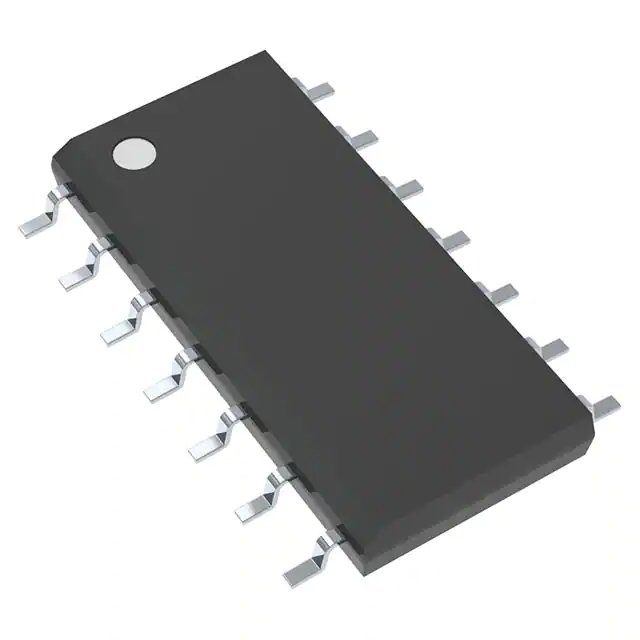
- Part No.:
- MC14025BDG
- Manufacturer:
- onsemi
- Category:
- Gates and Inverters
- Package:
- 14-SOIC (0.154", 3.90mm Width)
- Datasheet:
-
 MC14025BDG.pdf
- Description:
- IC GATE NOR 3CH 3-INP 14SOIC
- Quantity:
- Payment:

- Shipping:

Inventory:102
Please send an inquiry. Send us your inquiry, and we will respond immediately.
Product details
Overview
MC14025BDG from onsemi is a triple 3-input NOR gate CMOS logic IC in SOIC-14 package, operating from 3.0 V to 18.0 V supply, delivering ±10 mA output drive per pin, with guaranteed DC noise margins of 1.0 V (at 5 V), 2.0 V (at 10 V), and 2.5 V (at 15 V), used in low-power industrial control and noise-immune digital interface circuits.
For engineers reviewing the MC14025BDG datasheet, pinout, applications, or equivalent options, this page provides verified functional identity, validated pin assignments, confirmed voltage and timing specifications, real-world application contexts, and two technically documented alternative parts for design flexibility.
Technical Context
The MC14025BDG implements three independent 3-input NOR gates using complementary MOS (CMOS) P- and N-channel enhancement-mode transistors in a monolithic structure, enabling rail-to-rail output swing and high input impedance. Each gate features buffered outputs and double diode input protection (except triple diode on select variants).
It operates across −55 °C to +125 °C ambient temperature, supports dynamic loading up to 50 pF per gate, and exhibits propagation delays ranging from 40 ns (typical at VDD = 15 V, CL = 50 pF) to 200 ns (max at VDD = 5 V), with rise/fall times tightly bounded by load capacitance and supply voltage.
Key Specifications
| Parameter | Value and Actual Design Meaning |
|---|---|
| Logic Function | Triple 3-input NOR gate - three independent gates, each requiring all three inputs HIGH to assert LOW output. |
| Supply Voltage Range | 3.0 Vdc to 18.0 Vdc - enables direct compatibility with legacy 5 V, 10 V, and 15 V logic systems without level shifting. |
| Output Drive Capability | ±10 mA per pin - sufficient to drive two low-power TTL loads or one low-power Schottky TTL load over full temperature range. |
| DC Noise Margin | 1.0 V (5 V supply), 2.0 V (10 V), 2.5 V (15 V) - ensures robust operation in electrically noisy industrial environments. |
| Input Capacitance | 7.5 pF - low capacitive loading minimizes signal distortion and timing skew in high-speed routing. |
| Quiescent Current | 0.25 µA (typ @ 5 V), 1.0 µA (max @ 15 V) - ultra-low static power ideal for battery-backed or energy-constrained systems. |
| Propagation Delay | 40–200 ns (VDD = 5–15 V, CL = 50 pF) - predictable timing behavior across wide voltage and temperature ranges. |
Pinout & Package
MC14025BDG is housed in a 14-pin SOIC (Small Outline Integrated Circuit) package, case 751A, Pb-free, with 1.27 mm pitch, 8.55–8.75 mm body length, and 3.80–4.00 mm width - compatible with standard surface-mount reflow profiles.
| Pin/Terminal | Circuit Role | Design Meaning |
|---|---|---|
| 1, 2, 5, 6, 8, 9, 10, 11, 12, 13 | Input/Output terminals for three NOR gates | Pins 1/2/8 = Gate A inputs; Pin 3 = Gate A output; Pins 5/6/11 = Gate B inputs; Pin 4 = Gate B output; Pins 9/10/12 = Gate C inputs; Pin 13 = Gate C output. |
| 7 | VSS (Ground) | Common reference node for all logic and power domains; must be connected to system ground plane. |
| 14 | VDD (Supply) | Positive supply rail; decoupling capacitor (0.1 µF ceramic) required within 5 mm of this pin. |
Key Features
| Feature | Design Value |
|---|---|
| Wide supply range (3–18 V) | Eliminates need for separate voltage regulators in mixed-supply systems; supports direct integration with analog rails. |
| Pin-for-pin replacement for CD4025B | Enables drop-in upgrade path from legacy CD4000-series designs without PCB revision. |
| Double diode input protection | Provides ESD resilience >3 kV (HBM); protects against transient coupling in unshielded industrial wiring. |
| Buffered outputs | Reduces output impedance variation across logic states, improving fan-out consistency and waveform integrity. |
| −55 °C to +125 °C operation | Validated for under-hood automotive, motor drive control, and outdoor industrial equipment deployments. |
Applications
| Industrial PLC Input Conditioning | Legacy System Logic Translation |
|---|---|
Use Scenario: Converting noisy 12 V sensor switch signals into clean 5 V-compatible logic levels for microcontroller GPIOs in factory automation cabinets. IC Role / Device Role / Timing Role: NOR gate configured as inverter + OR combiner to debounce and validate dual-redundant limit switches. Use Value: 2.0 V DC noise margin at 10 V supply rejects common-mode transients from solenoid drivers and AC contactors. |
Use Scenario: Replacing obsolete CD4025BE in a 1980s test instrument where original 15 V logic rails remain active. IC Role / Device Role / Timing Role: Performing 3-input NOR logic for address decoding and bus arbitration in vintage CPU expansion slots. Use Value: Identical pinout and electrical behavior allows zero-change board-level replacement while adding Pb-free compliance. |
| Low-Power Remote Sensor Hub | Motor Control Safety Interlock |
Use Scenario: Aggregating fault signals from three independent temperature sensors in a solar inverter's DC string monitoring unit. IC Role / Device Role / Timing Role: NOR-based wired-OR fault detection: any sensor HIGH triggers system shutdown via single output line. Use Value: 0.25 µA quiescent current at 5 V extends battery life in wireless sensor nodes operating intermittently for years. |
Use Scenario: Enforcing hardware-enforced mutual exclusion between forward/reverse enable lines in a BLDC motor driver. IC Role / Device Role / Timing Role: Three-input NOR gate ensures both direction signals and brake command cannot be asserted simultaneously. Use Value: Guaranteed 10 mA sink/source capability drives optocoupler LEDs directly without external transistor buffering. |
Equivalent & Alternatives
The following parts are listed as comparable options for similar 3-input NOR gate applications.
| Alternative Part | Technical Difference | Application Difference | Selection Advice |
|---|---|---|---|
| CD4025BM96 | Same logic function and pinout; wider max supply (20 V), higher max IO (±20 mA), but only rated to +85 °C ambient. | Preferred for high-current 12 V systems with moderate temperature requirements; not suitable for extended-temperature industrial use. | Select when higher drive strength is needed and thermal environment stays below 85 °C. |
| 74HC25D,653 | CMOS variant with 2–6 V supply range, faster propagation (15 ns typ), but lower noise margin (0.9 V @ 4.5 V) and no 15 V operation. | Optimized for modern 3.3 V/5 V microcontroller interfaces; incompatible with legacy 10–15 V logic buses. | Select for speed-critical 5 V digital subsystems where supply voltage is strictly regulated and noise immunity is secondary. |
Compared with CD4025BM96 and 74HC25D,653, the MC14025BDG uniquely balances extended temperature support (−55 °C to +125 °C), wide-voltage operation (3–18 V), and industrial-grade noise immunity - making it the only choice for legacy-compatible, high-reliability embedded control where environmental stress and supply variability are design constraints.
Availability
MC14025BDG is available at Aetrix Electronics and suitable for industrial PLCs, legacy system upgrades, low-power sensor hubs, motor safety interlocks, and noise-immune digital interface circuits requiring stable component supply across long product lifecycles.
Supply support for MC14025BDG includes scheduled delivery planning, volume procurement assistance, BOM continuity management, traceable sourcing, and lifecycle availability coordination for OEM customers, industrial embedded developers, connected-device designers, and electronics production programs.
Manufacturer
onsemi (formerly ON Semiconductor) is a global semiconductor supplier specializing in energy-efficient power management, analog, logic, and discrete devices for automotive, industrial, and cloud infrastructure markets.
The MC14025BDG belongs to the B-Series CMOS logic family, designed specifically for applications demanding low static power, high noise immunity, and wide supply voltage tolerance in harsh or legacy-replacement environments.
FAQ
What is the logic configuration of the MC14025BDG?
The MC14025BDG contains three independent 3-input NOR gates. Each gate outputs LOW only when all three inputs are HIGH; otherwise, the output is HIGH. This configuration is confirmed in the device description section of the official datasheet and matches the logic diagram on page 2. The MC14025BDG does not include internal inverters or additional logic elements beyond the three NOR functions.
Does the MC14025BDG support 15 V operation?
Yes, the MC14025BDG is fully specified for 15 V DC operation: maximum supply voltage is +18.0 V, and electrical characteristics including VOH (≥14.95 V), VOL (≤0.05 V), and DC noise margin (2.5 V) are guaranteed at VDD = 15 V. This makes the MC14025BDG suitable for direct use in legacy 15 V logic systems without level translation.
What is the recommended handling for unused inputs on the MC14025BDG?
All unused inputs on the MC14025BDG must be tied to VSS (ground), as explicitly stated in the datasheet: "All unused inputs of OR, NOR gates must be connected to VSS." Leaving inputs floating risks metastability, increased power consumption, and potential latch-up due to CMOS high-impedance inputs. Tying to VSS ensures deterministic logic state and stable operation.
Is the MC14025BDG pin-compatible with the CD4025B series?
Yes, the MC14025BDG is explicitly documented as a pin-for-pin replacement for corresponding CD4000-series B-suffix devices, including CD4025B. The pin assignments, logic function, and electrical behavior match identically - enabling direct substitution in existing designs without layout changes, provided thermal and packaging constraints (SOIC vs. PDIP) are accounted for.
What is the maximum output current per pin for the MC14025BDG?
The absolute maximum output current per pin for the MC14025BDG is ±10 mA, as defined in the Maximum Ratings table. This value applies to both sourcing (IOH) and sinking (IOL) under DC or transient conditions. Exceeding this limit risks permanent damage. Actual usable drive depends on VDD and temperature - e.g., at VDD = 5 V and TA = 25 °C, typical IOL is 0.64 mA, rising to 4.2 mA at VDD = 15 V.
MC14025BDG Specifications
- Product attributes
- Attribute value
- Manufacturer:
- onsemi
- Series:
- 4000B
- Package/Case:
- 14-SOIC (0.154", 3.90mm Width)
- Packaging:
- Tube
- Product Status:
- Active
- Logic Type:
- NOR Gate
- Number of Circuits:
- 3
- Number of Inputs:
- 3
- Features:
- -
- Voltage - Supply:
- 3V ~ 18V
- Current - Quiescent (Max):
- 1 µA
- Current - Output High, Low:
- 8.8mA, 8.8mA
- Input Logic Level - Low:
- 1.5V ~ 4V
- Input Logic Level - High:
- 3.5V ~ 11V
- Max Propagation Delay @ V, Max CL:
- 100ns @ 15V, 50pF
- Operating Temperature:
- -55°C ~ 125°C
- Grade:
- -
- Qualification:
- -
- Mounting Type:
- Surface Mount
- Supplier Device Package:
- 14-SOIC
MC14025BDG FAQ
1.How can I place an order for MC14025BDG through Aetrix?
Please submit a Request for Quotation (RFQ) for MC14025BDG on Aetrix. Our sales agent will provide a competitive quotation and guide you through the order confirmation once you accept the terms.
2.Are the price and stock information for MC14025BDG reliable?
The price and inventory of MC14025BDG are updated periodically and may fluctuate due to market conditions. Stock and pricing data are typically refreshed every 24 hours. Quotation validity for MC14025BDG is usually 5 days.
3.What payment methods are accepted for MC14025BDG?
We accept Wire Transfer, PayPal, Credit Card, Western Union, MoneyGram, and Escrow for MC14025BDG transactions.
Note: Certain payment methods may incur a processing fee.
4.How is shipping managed for MC14025BDG?
MC14025BDG orders can be shipped via leading logistics carriers, including DHL, UPS, FedEx, TNT, or Registered Mail.
Once your MC14025BDG order is processed, you will receive an email with the shipment details and tracking number.
Note: Tracking information may take up to 24 hours to appear. Express delivery typically takes 3–5 business days.
5.How can I obtain technical support or documentation for MC14025BDG?
For technical support, including MC14025BDG datasheets, pinout diagrams, or application guidance, please contact our engineering support team. They can provide detailed documentation and assistance for your MC14025BDG requirements.
6.How does Aetrix verify that MC14025BDG is sourced from the original manufacturer or authorized distributors?
All MC14025BDG products on Aetrix are procured from qualified distributors and authorized channels. Our dedicated quality assurance team conducts strict verification, including traceability checks and, if necessary, third-party testing. This ensures that MC14025BDG meets industry standards.
7.What is the process for return or replacement of MC14025BDG?
All MC14025BDG units undergo pre-shipment inspection (PSI). If there is an issue with MC14025BDG, returns or replacements are accepted under the following conditions:
1.Quantity discrepancies, incorrect items, or visible external defects (such as breakage or corrosion), acknowledged by Aetrix.
2.The issue is reported within 90 days of delivery.
3.The MC14025BDG part is unused and in its original packaging.
Return procedure for MC14025BDG:
1.Submit a request within 90 days.
2.Obtain a Return Material Authorization (RMA) from Aetrix.
MC14025BDG Tags

-
SN74LVC1G14DBVR
Texas Instruments

-
SN74LVC1G14DCKR
Texas Instruments
-
SN74AHC1G14DBVR
Texas Instruments
-
SN74LVC1G08DBVR
Texas Instruments
-
SN74LVC1G08DCKR
Texas Instruments
-
SN74LVC1G32DCKR
Texas Instruments
-
SN74LVC1G04DBVR
Texas Instruments
.jpg)
-
74LVC1G08GW,125
Nexperia USA Inc.
-
SN74LVC1G04DCKR
Texas Instruments
-
SN74AHC1G08DBVR
Texas Instruments
-
SN74LVC1G32DBVR
Texas Instruments
-
SN74AHCT1G08DBVR
Texas Instruments
Tech Hub

Counterfeit components can hide behind convincing markings and passing basic function tests. This engineering reference covers source traceability, external inspection, X-ray, XRF, electrical testing, …

A practical engineering and sourcing framework covering lifecycle verification, lifetime-buy calculations, replacement qualification, supplier checks and counterfeit-risk controls.

TTL and CMOS logic families differ in thresholds, loading, output drive, power and timing. This engineering guide compares 74HC and 74HCT, calculates noise margins and checks 3.3 V/5 V compatibility.

A practical engineering guide to 3.3V and 5V logic compatibility, input thresholds, resistor dividers, translator ICs, MOSFET level shifting, I2C pull-ups, timing limits and power-sequencing risks.

The 74HC595 uses push-pull logic outputs, while the TPIC6B595 uses 50 V open-drain DMOS sinks for higher-power loads. This guide compares timing, current limits, 3.3 V interfacing, load wiring, thermal…

The 74HC595 converts serial data into eight stable parallel outputs. This guide covers pin functions, shift and storage timing, OE and MR behavior, drive-current limits, cascading, voltage compatibilit…

A technical comparison of level-sensitive latches and edge-triggered flip-flops, covering timing windows, setup and hold limits, master–slave operation, time borrowing, race-through, HDL inference and…

A D latch stores one bit while Enable controls when data can pass. This reference covers gate-level operation, truth tables, transparency, setup and hold timing, LE versus OE, common ICs and practical …

An SR latch stores one bit through cross-coupled feedback. This engineering reference covers NOR and NAND implementations, truth tables, forbidden-state recovery, gated operation, switch debouncing, fa…

Latch circuits retain one bit through feedback. This technical reference covers SR and D latches, truth tables, transparency, timing limits, latch-versus-flip-flop behavior, applications and common log…


