
 My Inquiry
 My Account


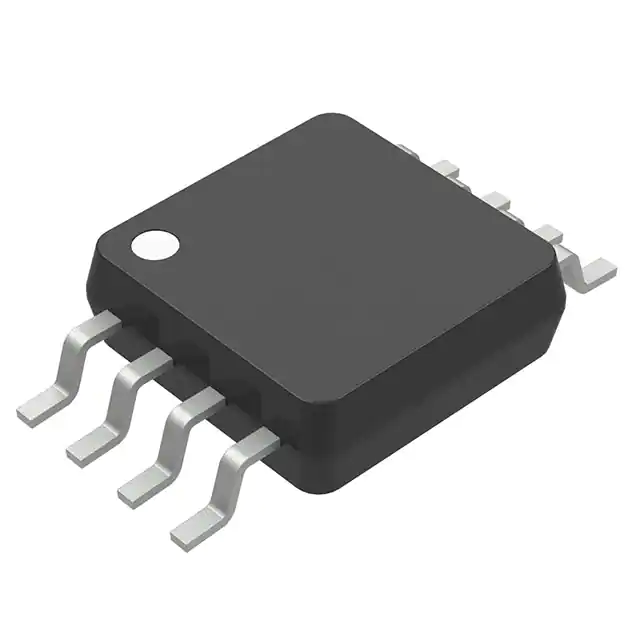
onsemi MC33565DMR2G
- Part No.:
- MC33565DMR2G
- Manufacturer:
- onsemi
- Package:
- 8-TSSOP, 8-MSOP (0.118", 3.00mm Width)
- Datasheet:
-
 MC33565DMR2G.pdf
- Description:
- IC REG LINEAR 3.3V 200MA MICRO8
- Quantity:
- Payment:

- Shipping:

Inventory:3,317
Please send an inquiry. Send us your inquiry, and we will respond immediately.
Product details
Overview
MC33565DMR2G from onsemi is a smart dual-input 3.3 V low-dropout voltage regulator with integrated low-voltage detector and external P-channel MOSFET switch drive, designed for glitch-free 5.0 V ↔ 3.3 V transitions in PCI/NIC peripheral cards. It delivers 200 mA regulated output, maintains ±2% output accuracy over −5°C to +150°C, features 4.02 V/4.17 V hysteresis thresholds, and prevents reverse current flow during sleep mode.
For engineers reviewing the MC33565DMR2G datasheet, pinout, applications, or equivalent options, key selection criteria include auxiliary-input quiescent current (1.9–3.0 mA), switch-drive rise/fall times (1.4 µs / 0.65 µs), sense-input regulation capability, thermal shutdown at ~170°C, and Pb-free Micro8 package compatibility with ACPI-compliant power management systems.
Technical Context
The MC33565DMR2G implements a dual-supply architecture where internal LDO regulation engages when main input (Pin 1) exceeds 4.02 V, while below that threshold it disables the LDO and asserts low-level gate drive (Pin 8) to enable an external P-channel MOSFET, sourcing 3.3 V directly from the auxiliary input (Pin 3). Its low-voltage detector uses precision resistive divider feedback with 150 mV hysteresis to ensure noise-immune mode switching.
Regulation relies on remote sense (Pin 6) connected directly to the load for tight line/load regulation (≤1.9 mV), while internal NPN pass device blocks reverse current (<25 µA at TJ = 25°C). External compensation requires ≥4.7 µF output capacitor with ESR ≤500 mΩ to maintain phase margin >60° across 0–200 mA load range.
Key Specifications
| Parameter | Value and Actual Design Meaning |
|---|---|
| Output Voltage | 3.3 V ±2% over −5°C to +150°C - ensures stable logic supply for 3.3 V I/O interfaces under full thermal stress |
| Max Output Current | 200 mA - supports typical PCI/NIC card logic loads without external boost circuitry |
| Main Input Thresholds | Vth(L) = 4.02 V, Vth(H) = 4.17 V - enables reliable ACPI S3/S4 state detection with 150 mV hysteresis |
| Switch Drive Rise/Fall Time | tDH = 1.4 µs, tDL = 0.65 µs (CL = 1.2 nF) - ensures fast, controlled MOSFET turn-on/off during supply transitions |
| Line & Load Regulation | ≤13.2 mV - minimizes output deviation during rail droop or dynamic load steps |
| Quiescent Current (Aux) | 1.9–3.0 mA - enables ultra-low-power sleep-mode operation without compromising wake-up speed |
| Reverse Leakage (Main) | ≤25 µA at TJ = 25°C - prevents auxiliary rail discharge through regulator during sleep mode |
Pinout & Package
MC33565DMR2G is housed in a Pb-free Micro8 (MSOP-8) package (Case 846A), 3.0 mm × 3.0 mm × 1.0 mm, with exposed pad for thermal enhancement. Pin 1 is marked by dot; pins 2 and 5 are NC (no internal connection).
| Pin/Terminal | Circuit Role | Design Meaning |
|---|---|---|
| 1 (Main Input) | Main 5.0 V supply input | Connects to system 5 V rail; triggers LDO regulation above 4.02 V |
| 2, 5 (NC) | No connection | Not bonded internally - must remain unconnected on PCB |
| 3 (Auxiliary Input) | Auxiliary 3.3 V supply input | Sources output during sleep mode via external P-MOSFET when main rail fails |
| 4 (Gnd) | Power ground reference | Common return for regulator, detector, and switch drive circuits |
| 6 (Sense Input) | Remote output voltage sensing | Enables precise load-point regulation by closing feedback loop at the load |
| 7 (Regulator Output) | 3.3 V regulated output | Delivers up to 200 mA; connects directly to load and sense point |
| 8 (Switch Drive) | P-MOSFET gate driver | Drives external high-side P-channel switch; sinks 15–22 mA peak during turn-on |
Key Features
| Feature | Design Value |
|---|---|
| Glitch-free sleep-to-active transition | Eliminates output dropout during 5 V → 3.3 V supply handoff using hysteresis-controlled MOSFET gating |
| ACPI-compliant power management | Fully satisfies Intel/Microsoft/Toshiba instantly available requirements for PCI/NIC hot-plug and state transitions |
| Reverse current blocking | Internal NPN pass device limits reverse leakage to <25 µA, preserving auxiliary rail integrity |
| Thermal shutdown protection | Disables output at ~170°C junction temperature to prevent catastrophic failure under sustained overload |
| External P-MOSFET control | Provides scalable current handling beyond 200 mA by selecting appropriate external FET (e.g., MGSF1P02ELT) |
Applications
| PCI Express Add-in Cards | Network Interface Cards (NIC) |
|---|---|
Use Scenario: Hot-plug insertion of PCIe expansion cards into powered-backplane systems requiring seamless 5 V ↔ 3.3 V supply arbitration. IC Role / Device Role / Timing Role: Smart voltage supervisor and dual-path regulator managing rail handoff between main and standby supplies. Use Value: Prevents brownout-induced firmware crash during insertion by maintaining uninterrupted 3.3 V to PCIe controller and PHY. | Use Scenario: Ethernet NICs operating in ACPI S3 (suspend-to-RAM) mode where 5 V main rail is removed but 3.3 V auxiliary remains active. IC Role / Device Role / Timing Role: Sleep-mode power manager enabling instant wake-on-LAN via continuous 3.3 V supply to MAC and PHY. Use Value: Achieves sub-100 µs wake latency by eliminating boot-time regulator initialization delay. |
| Industrial Peripheral Modules | Embedded Computing Carrier Boards |
Use Scenario: Modular I/O carrier boards with interchangeable mezzanine modules requiring independent 3.3 V domain control per slot. IC Role / Device Role / Timing Role: Slot-level power arbitrator ensuring each module receives clean 3.3 V regardless of host rail status. Use Value: Enables hot-swap maintenance without powering down entire system or affecting neighboring slots. | Use Scenario: COM Express or SMARC carrier boards supporting multiple low-power compute modules with shared 5 V/3.3 V rails. IC Role / Device Role / Timing Role: Redundant 3.3 V source selector providing failover between primary and backup supplies. Use Value: Increases system uptime by sustaining critical management controllers during primary rail fault. |
Equivalent & Alternatives
The following parts are listed as comparable options for similar dual-input LDO regulator applications.
| Alternative Part | Technical Difference | Application Difference | Selection Advice |
|---|---|---|---|
| NCP33565DMR2G | Same die, rebranded by onsemi post-acquisition; identical electrical specs and pinout | No functional difference - legacy part number used in older BOMs | Select MC33565DMR2G for new designs to ensure long-term availability and support |
| TPS7A6033QDGKRQ1 | Single-input automotive-grade LDO (5 V → 3.3 V); no auxiliary input or switch drive; fixed 3.3 V output | Lacks sleep-mode bypass capability - unsuitable for ACPI-compliant hot-swap or dual-rail arbitration | Only viable if system uses only one supply rail and does not require glitch-free transitions |
Compared with NCP33565DMR2G, MC33565DMR2G offers identical performance but reflects updated onsemi branding and lifecycle management; versus TPS7A6033QDGKRQ1, it provides unique dual-input arbitration and external FET control essential for peripheral card power sequencing - a capability absent in single-rail alternatives.
Availability
MC33565DMR2G is available at Aetrix Electronics and suitable for PCI/NIC card design, industrial peripheral modules, and embedded carrier board development requiring stable component supply, Pb-free compliance, and guaranteed long-term manufacturability.
Supply support for MC33565DMR2G includes scheduled delivery planning, volume procurement assistance, BOM continuity management, traceable sourcing, and lifecycle availability coordination for OEM customers, industrial embedded developers, connected-device designers, and electronics production programs.
Manufacturer
onsemi (formerly ON Semiconductor) is a global semiconductor supplier specializing in energy-efficient power management, analog, sensor, and connectivity solutions for automotive, industrial, cloud, and IoT applications.
The MC33565DMR2G belongs to onsemi's Smart Power Management product line, engineered specifically for ACPI-compliant computer peripheral cards needing robust, glitch-free dual-rail voltage arbitration and seamless sleep/active transitions.
FAQ
What is the primary function of the MC33565DMR2G in a peripheral card design?
The MC33565DMR2G serves as a smart dual-input 3.3 V regulator that automatically switches between a 5.0 V main supply and a 3.3 V auxiliary supply to maintain uninterrupted power during ACPI sleep-to-active transitions. In the MC33565DMR2G, this is achieved via internal LDO regulation above 4.02 V and external P-MOSFET bypass below that threshold - ensuring zero-output-glitch behavior critical for PCI/NIC reliability.
Does the MC33565DMR2G require an external capacitor for stability, and what are the specifications?
Yes, the MC33565DMR2G requires an external output compensation capacitor of minimum 4.7 µF with ESR ≤500 mΩ for loop stability across temperature and load. This capacitor must be placed close to Pin 7 (Regulator Output) and Pin 6 (Sense Input); increasing capacitance improves load transient response. The MC33565DMR2G datasheet specifies these values as mandatory for maintaining ≥60° phase margin at full 200 mA load.
Can the MC33565DMR2G operate without connecting the Sense Input (Pin 6)?
No - the Sense Input (Pin 6) is required for correct MC33565DMR2G operation. It closes the feedback loop at the load to achieve tight line and load regulation (≤13.2 mV). Leaving Pin 6 unconnected degrades regulation accuracy and may cause instability or thermal shutdown under varying load conditions. The MC33565DMR2G functional block diagram and operating description explicitly mandate its use.
What is the maximum junction temperature before thermal shutdown activates in the MC33565DMR2G?
The MC33565DMR2G activates thermal shutdown at approximately 170°C junction temperature to protect against catastrophic failure. Unlike many regulators, it has no built-in hysteresis - so repeated cycling may occur if cooling is insufficient. The MC33565DMR2G's RθJA is 172°C/W in Micro8 package; proper PCB copper area and airflow are essential to keep TJ below 150°C under 200 mA load.
Is the MC33565DMR2G pin-compatible with SOIC-8 versions like MC33565DR2G?
No - the MC33565DMR2G uses Micro8 (MSOP-8) packaging with different pin spacing (0.5 mm pitch) and footprint than SOIC-8 (1.27 mm pitch); although pin functions are identical, direct PCB replacement is not possible. The MC33565DMR2G requires dedicated layout for its 3.0 mm × 3.0 mm body and exposed thermal pad, unlike the larger SOIC-8 variants such as MC33565DR2G.
MC33565DMR2G Specifications
- Product attributes
- Attribute value
- Manufacturer:
- onsemi
- Series:
- -
- Package/Case:
- 8-TSSOP, 8-MSOP (0.118", 3.00mm Width)
- Packaging:
- Tape & Reel (TR)
- Product Status:
- Obsolete
- Output Configuration:
- Positive
- Output Type:
- Fixed
- Number of Regulators:
- 1
- Voltage - Input (Max):
- 5.5V
- Voltage - Output (Min/Fixed):
- 3.3V
- Voltage - Output (Max):
- -
- Voltage Dropout (Max):
- -
- Current - Output:
- 200mA
- Current - Quiescent (Iq):
- 10 mA
- Current - Supply (Max):
- -
- PSRR:
- -
- Control Features:
- -
- Protection Features:
- Over Temperature, Short Circuit
- Operating Temperature:
- -5°C ~ 150°C
- Grade:
- -
- Qualification:
- -
- Mounting Type:
- Surface Mount
- Supplier Device Package:
- 8-MSOP
MC33565DMR2G FAQ
1.How can I place an order for MC33565DMR2G through Aetrix?
Please submit a Request for Quotation (RFQ) for MC33565DMR2G on Aetrix. Our sales agent will provide a competitive quotation and guide you through the order confirmation once you accept the terms.
2.Are the price and stock information for MC33565DMR2G reliable?
The price and inventory of MC33565DMR2G are updated periodically and may fluctuate due to market conditions. Stock and pricing data are typically refreshed every 24 hours. Quotation validity for MC33565DMR2G is usually 5 days.
3.What payment methods are accepted for MC33565DMR2G?
We accept Wire Transfer, PayPal, Credit Card, Western Union, MoneyGram, and Escrow for MC33565DMR2G transactions.
Note: Certain payment methods may incur a processing fee.
4.How is shipping managed for MC33565DMR2G?
MC33565DMR2G orders can be shipped via leading logistics carriers, including DHL, UPS, FedEx, TNT, or Registered Mail.
Once your MC33565DMR2G order is processed, you will receive an email with the shipment details and tracking number.
Note: Tracking information may take up to 24 hours to appear. Express delivery typically takes 3–5 business days.
5.How can I obtain technical support or documentation for MC33565DMR2G?
For technical support, including MC33565DMR2G datasheets, pinout diagrams, or application guidance, please contact our engineering support team. They can provide detailed documentation and assistance for your MC33565DMR2G requirements.
6.How does Aetrix verify that MC33565DMR2G is sourced from the original manufacturer or authorized distributors?
All MC33565DMR2G products on Aetrix are procured from qualified distributors and authorized channels. Our dedicated quality assurance team conducts strict verification, including traceability checks and, if necessary, third-party testing. This ensures that MC33565DMR2G meets industry standards.
7.What is the process for return or replacement of MC33565DMR2G?
All MC33565DMR2G units undergo pre-shipment inspection (PSI). If there is an issue with MC33565DMR2G, returns or replacements are accepted under the following conditions:
1.Quantity discrepancies, incorrect items, or visible external defects (such as breakage or corrosion), acknowledged by Aetrix.
2.The issue is reported within 90 days of delivery.
3.The MC33565DMR2G part is unused and in its original packaging.
Return procedure for MC33565DMR2G:
1.Submit a request within 90 days.
2.Obtain a Return Material Authorization (RMA) from Aetrix.
MC33565DMR2G Tags

-
MIC5504-1.8YM5-TR
Microchip Technology
-
MIC5504-3.3YM5-TR
Microchip Technology

-
MIC5365-3.0YC5-TR
Microchip Technology
-
MIC5365-1.8YC5-TR
Microchip Technology
-
MIC5365-2.5YC5-TR
Microchip Technology
-
MIC5365-3.3YC5-TR
Microchip Technology

-
MIC5365-3.3YD5-TR
Microchip Technology

-
MIC5317-3.3YM5-TR
Microchip Technology

-
TLV1117LV33DCYR
Texas Instruments

-
MIC5317-3.3YMT-TZ
Microchip Technology

-
MIC5528-3.3YMT-TR
Microchip Technology

-
TLV75801PDRVR
Texas Instruments
Tech Hub

Counterfeit components can hide behind convincing markings and passing basic function tests. This engineering reference covers source traceability, external inspection, X-ray, XRF, electrical testing, …

A practical engineering and sourcing framework covering lifecycle verification, lifetime-buy calculations, replacement qualification, supplier checks and counterfeit-risk controls.

TTL and CMOS logic families differ in thresholds, loading, output drive, power and timing. This engineering guide compares 74HC and 74HCT, calculates noise margins and checks 3.3 V/5 V compatibility.

A practical engineering guide to 3.3V and 5V logic compatibility, input thresholds, resistor dividers, translator ICs, MOSFET level shifting, I2C pull-ups, timing limits and power-sequencing risks.

The 74HC595 uses push-pull logic outputs, while the TPIC6B595 uses 50 V open-drain DMOS sinks for higher-power loads. This guide compares timing, current limits, 3.3 V interfacing, load wiring, thermal…

The 74HC595 converts serial data into eight stable parallel outputs. This guide covers pin functions, shift and storage timing, OE and MR behavior, drive-current limits, cascading, voltage compatibilit…

A technical comparison of level-sensitive latches and edge-triggered flip-flops, covering timing windows, setup and hold limits, master–slave operation, time borrowing, race-through, HDL inference and…

A D latch stores one bit while Enable controls when data can pass. This reference covers gate-level operation, truth tables, transparency, setup and hold timing, LE versus OE, common ICs and practical …

An SR latch stores one bit through cross-coupled feedback. This engineering reference covers NOR and NAND implementations, truth tables, forbidden-state recovery, gated operation, switch debouncing, fa…

Latch circuits retain one bit through feedback. This technical reference covers SR and D latches, truth tables, transparency, timing limits, latch-versus-flip-flop behavior, applications and common log…


