
 My Inquiry
 My Account


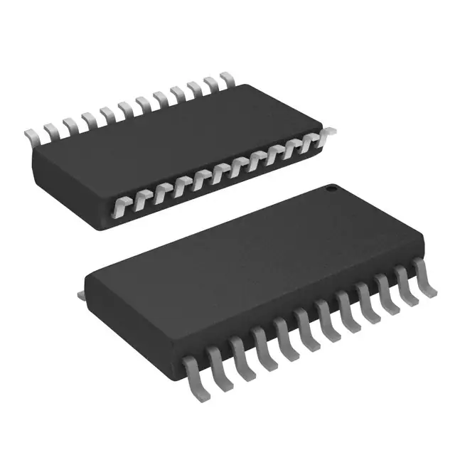
NXP Semiconductors MC33941EGR2
- Part No.:
- MC33941EGR2
- Manufacturer:
- NXP Semiconductors
- Category:
- Sensor, Transducer Amplifiers
- Package:
- Datasheet:
-
 MC33941EGR2.pdf
- Description:
- SENSOR IC TOUCH/PROXMTY 24SOIC
- Quantity:
- Payment:

- Shipping:

Inventory:2,616
Please send an inquiry. Send us your inquiry, and we will respond immediately.
Product details
Overview
MC33941EGR2 from Freescale Semiconductor is an electric field imaging device designed for non-contact proximity and capacitive touch sensing in cost-sensitive industrial and appliance systems. It integrates a tunable 120 kHz sine wave generator (±10% stability), supports up to 7 electrodes with 3-bit multiplexed selection (A/B/C), delivers 5 V regulated output (4.75–5.25 V at 75 mA), and operates across –40°C to 110°C. Used in refrigerator frost detection, garage door safety sensors, and linear sliders.
For engineers reviewing the MC33941EGR2 datasheet, MC33941EGR2 pinout, MC33941EGR2 application, or MC33941EGR2 equivalent, this page provides verified specifications, electrode multiplexing logic, shield driver functionality, LPF response tuning via LPCAP, and validated alternatives for E-field sensing system design.
Technical Context
The MC33941EGR2 implements a dedicated analog front-end for electric field imaging: its oscillator generates a low-harmonic sine wave (–20 dBc 2nd–4th harmonics) adjustable via ROSC resistor (60/120/240 kHz); a 7-channel analog multiplexer routes drive/receive signals under A/B/C control; and internal gain/offset circuitry (AREC = 4.0 AV, VRECOFF = –3.0 V) converts electrode AC amplitude into a DC-level output at LEVEL pin.
It includes dual ground domains (AGND/DGND), a shield driver (SDGBW = 4.5 MHz, SDHARM ≤ –20 dBc) for coaxial cable noise rejection, and two independent regulators - VDDCAP for internal analog supply and VCCCAP for external 5 V load (75 mA max). Electrode signal integrity is maintained by internal grounding of unselected E1–E7 pins.
Key Specifications
| Parameter | Value and Actual Design Meaning |
|---|---|
| Operating Frequency | 120 kHz nominal (tunable to 60/240 kHz via ROSC resistor); optimized for linear C-to-V response over 10–70 pF range |
| Electrode Support | 7 independent electrode inputs (E1–E7); selected via 3-bit A/B/C logic per Table 5 |
| Harmonic Content | ≤ –20 dBc (2nd–4th harmonics); reduces interference in multi-sensor or noisy EMI environments |
| 5 V Regulator Output | 4.75–5.25 V at up to 75 mA (VCCCAP); powers MCU peripherals or external logic without auxiliary LDO |
| Response Time Tuning | Adjustable via external LPCAP capacitor: 10 nF → ~1.5 ms; 1 nF → < 200 μs (trade-off with noise) |
| Temperature Range | –40°C to +110°C ambient; qualified for automotive interior and industrial control environments |
| Shield Driver Bandwidth | 4.5 MHz GBW at 120 kHz; enables active cancellation of cable capacitance in remote electrode configurations |
Pinout & Package
MC33941EGR2 is housed in a 24-terminal SOICW package (Case 751E-05, 7.5 mm width), with exposed thermal pad not connected internally. Pin 1 is DGND; Pins 2 and 24 are no-connect; Pin 15 is main GND; AGND (Pin 13) and DGND (Pin 1) must be tied at single-point ground.
| Pin/Terminal | Circuit Role | Design Meaning |
|---|---|---|
| DGND (1) | Digital ground reference | Return path for digital logic (A/B/C, SHIELDEN); separate from AGND but tied at system star point |
| N/C (2, 24) | No connection | Must remain unconnected; no internal bonding or function |
| SHIELDEN (3) | Shield driver enable control | Active-high logic input; enables SHIELD output only when driven high (e.g., during active electrode measurement) |
| C/B/A (4–6) | Electrode selection address | 3-bit binary code selects one of E1–E7 (Table 5); all 0 disables all electrodes |
| LEVEL (7) | Processed electrode output | Analog DC voltage proportional to 1/C of selected electrode; used directly by MCU ADC |
| LPCAP (8) | Low-pass filter node | External capacitor forms RC filter with internal resistor; sets system response time and noise bandwidth |
| ROSC (9) | Oscillator frequency set | Resistor to ground sets center frequency (e.g., 39 kΩ → 120 kHz); tolerance impacts stability (±10%) |
| VDDCAP (10) | Analog regulator bypass | 47 μF capacitor stabilizes internal analog supply; critical for low-noise electrode signal chain |
| VPWR (11) | Main power input | 9–18 V DC input; powers internal regulators and oscillator; withstands double-battery transients (26.5 V/1 min) |
| VCCCAP (12) | 5 V regulator output filter | 47 μF capacitor ensures stable 5 V output for external loads up to 75 mA |
| AGND (13) | Analog ground reference | Return for analog circuitry (oscillator, detector, gain stage); isolated from DGND to minimize coupling |
| SHIELD (14) | Active shield drive output | Buffered replica of electrode AC signal; cancels capacitive coupling in coaxial or shielded PCB layouts |
| GND (15) | Main IC ground | Primary ground tie point; connects to system chassis or PCB ground plane |
| TEST (16) | Factory test access | Connected to ground in normal operation; used internally for wafer-level testing |
| E1–E7 (17–23) | Electrode interface terminals | Each drives/receives 120 kHz sine wave; internally grounded when deselected to prevent crosstalk |
Key Features
| Feature | Design Value |
|---|---|
| 7-electrode multiplexed sensing | Reduces component count vs. discrete channel solutions; enables compact touch panels with shared analog front-end |
| Tunable oscillator frequency | Three discrete operating points (60/120/240 kHz) via ROSC resistor selection; extends usable capacitance range from 10 pF to 150 pF |
| Integrated 5 V regulator | Eliminates need for external LDO; supplies MCU I/O or LED drivers directly from VPWR input (9–18 V) |
| Shield driver with 4.5 MHz GBW | Enables reliable long-cable (>1 m) electrode connections by actively nulling shield-to-signal coupling |
| Adjustable response time via LPCAP | Capacitor value directly sets settling time/noise trade-off: 1 nF for fast wake-up (<200 μs), 10 nF for low-noise liquid level sensing |
| Extended temperature operation | Validated from –40°C to +110°C; supports under-hood automotive, refrigeration, and industrial enclosure deployments |
Applications
| Refrigerator Frost Detection | Garage Door Safety Sensing |
|---|---|
Use Scenario: Detecting ice buildup on evaporator coils inside household refrigerators using embedded electrodes behind plastic liner. IC Role / Device Role / Timing Role: MC33941EGR2 acts as the E-field transceiver, generating 120 kHz excitation and measuring capacitance shift caused by dielectric change from air→ice (k=3.2). Use Value: Enables maintenance-free, non-invasive frost monitoring without optical sensors or thermal probes; leverages inherent linearity at 120 kHz over 10–70 pF range. | Use Scenario: Preventing garage door closure when objects (e.g., children, pets) interrupt the electric field between door edge electrodes and frame. IC Role / Device Role / Timing Role: MC33941EGR2 serves as proximity detector with fast response mode (1 nF LPCAP), triggering immediate stop command upon capacitance increase >5 pF. Use Value: Achieves sub-200 μs reaction time and immunity to ambient light/dust-unlike IR or ultrasonic alternatives-while operating reliably at –40°C. |
| Linear Touch Slider Control | Industrial Spill-Over Flow Sensing |
Use Scenario: Replacing mechanical potentiometers in HVAC control panels with a 5-segment copper trace slider on FR4 PCB. IC Role / Device Role / Timing Role: MC33941EGR2 sequentially scans E1–E5 electrodes using A/B/C logic, converting position to weighted centroid voltage at LEVEL pin. Use Value: Delivers smooth 10-bit+ resolution via analog interpolation; avoids firmware-intensive digital correlation algorithms required by charge-transfer ICs. | Use Scenario: Monitoring liquid height in chemical tanks where conductive or corrosive fluids preclude float switches or ultrasonic transducers. IC Role / Device Role / Timing Role: MC33941EGR2 measures capacitance between parallel plate electrodes mounted externally on tank wall; dielectric shift (air→fluid, k=80) lowers LEVEL voltage. Use Value: Provides intrinsically safe, non-invasive level sensing without tank penetration; calibrated output voltage maps linearly to fill height using 60 kHz mode for extended 150 pF range. |
Equivalent & Alternatives
The following parts are listed as comparable options for similar electric field sensing applications.
| Alternative Part | Technical Difference | Application Difference | Selection Advice |
|---|---|---|---|
| MPR121 | 12-channel capacitive touch controller with I²C interface; integrated digital filtering and baseline tracking; no analog LEVEL output or shield driver | Designed for button/slider UIs with host MCU processing; lacks analog output for direct ADC use or remote electrode driving capability | Select MPR121 when system uses I²C host and requires auto-calibration; avoid when analog output, coax shielding, or high-temp operation (>85°C) is needed. |
| AT42QT2120 | 12-channel QTouch IC with burst-mode sensing; operates at 1 MHz; no external frequency tuning or shield driver; max TA = 85°C | Optimized for low-power consumer touch interfaces; incompatible with industrial temperature ranges or long-cable electrode layouts | Select AT42QT2120 for battery-powered UIs needing ultra-low quiescent current; avoid for automotive, appliance, or safety-critical proximity detection. |
Compared with MPR121 and AT42QT2120, the MC33941EGR2 uniquely provides analog-level output, active shield drive, ROSC-tunable frequency, and full –40°C to 110°C qualification-making it the only option for robust, analog-integrated E-field sensing in harsh environments.
Availability
MC33941EGR2 is available at Aetrix Electronics and suitable for refrigerator frost detection, garage door safety systems, linear touch sliders, and industrial spill-over flow sensing requiring stable component supply and long-term industrial lifecycle support.
Supply support for MC33941EGR2 includes scheduled delivery planning, volume procurement assistance, BOM continuity management, traceable sourcing, and lifecycle availability coordination for OEM customers, industrial embedded developers, connected-device designers, and electronics production programs.
Manufacturer
Freescale Semiconductor (now part of NXP Semiconductors) was a leading designer of embedded processors and analog/mixed-signal ICs for automotive, industrial, and consumer applications.
The MC33941EGR2 belongs to Freescale's Sensors & Analog Interface product line, engineered specifically for robust, low-cost electric field imaging in safety-critical and thermally demanding environments.
FAQ
What is the maximum number of electrodes supported by the MC33941EGR2?
The MC33941EGR2 supports up to 7 electrodes (E1–E7), selected individually via the 3-bit A/B/C address lines. Table 5 in the datasheet defines the binary mapping: e.g., CBA = 001 selects E1, while 111 selects E7. All electrodes are internally grounded when deselected to prevent crosstalk, and the shield driver (SHIELD/SHIELDEN) further isolates signals in multi-electrode layouts.
How does the MC33941EGR2 achieve immunity to cable capacitance in remote electrode applications?
The MC33941EGR2 achieves cable capacitance immunity through its integrated shield driver: when SHIELDEN is asserted high, the SHIELD pin outputs a buffered, phase-matched replica of the electrode AC signal. This cancels potential differences between signal and shield conductors-especially in coaxial cables-effectively eliminating stray capacitance effects. The shield driver's 4.5 MHz gain-bandwidth product ensures fidelity at the 120 kHz operating frequency used by MC33941EGR2.
Can the MC33941EGR2 operate outside the standard 120 kHz frequency?
Yes, the MC33941EGR2 supports three discrete operating frequencies: 60 kHz, 120 kHz, and 240 kHz, selected by changing the ROSC resistor value (82 kΩ, 39 kΩ, or 20 kΩ respectively). Each frequency shifts the optimal capacitance range-60 kHz extends sensitivity to 150 pF for liquid level sensing, while 240 kHz improves resolution below 10 pF. All variants maintain ≤ –20 dBc harmonic content and ±10% frequency stability.
What is the purpose of the LPCAP pin on the MC33941EGR2, and how does it affect system performance?
The LPCAP pin on the MC33941EGR2 connects to an external capacitor that forms a low-pass filter with an internal resistor, setting the system's response time and noise bandwidth. A 10 nF capacitor yields ~1.5 ms settling time for stable liquid level readings; reducing to 1 nF cuts response to <200 μs for fast wake-up proximity detection-but increases susceptibility to EMI. This direct hardware tuning avoids firmware-based filtering delays and preserves analog signal integrity in MC33941EGR2 designs.
Does the MC33941EGR2 include built-in voltage regulation, and what are its output capabilities?
Yes, the MC33941EGR2 integrates two regulators: a 5 V output (VCCCAP) rated for up to 75 mA and an internal analog supply (VDDCAP) filtered via external 47 μF capacitors. The 5 V regulator maintains 4.75–5.25 V across load currents from 1–75 mA and input VPWR from 7–18 V. It powers external MCUs, LEDs, or logic-eliminating need for a discrete LDO-and is explicitly characterized over the full –40°C to 110°C operating range of MC33941EGR2.
MC33941EGR2 Specifications
- Product attributes
- Attribute value
- Manufacturer:
- NXP Semiconductors
- Series:
- -
- Packaging:
- Tape & Reel (TR)
- Product Status:
- Obsolete
- Amplifier Type:
- External Input
- Voltage - Supply:
- 9V ~ 18V
- Output Type:
- Analog
- Current - Supply:
- 8 mA
- Operating Temperature:
- -40°C ~ 110°C
- Mounting Type:
- Surface Mount
MC33941EGR2 FAQ
1.How can I place an order for MC33941EGR2 through Aetrix?
Please submit a Request for Quotation (RFQ) for MC33941EGR2 on Aetrix. Our sales agent will provide a competitive quotation and guide you through the order confirmation once you accept the terms.
2.Are the price and stock information for MC33941EGR2 reliable?
The price and inventory of MC33941EGR2 are updated periodically and may fluctuate due to market conditions. Stock and pricing data are typically refreshed every 24 hours. Quotation validity for MC33941EGR2 is usually 5 days.
3.What payment methods are accepted for MC33941EGR2?
We accept Wire Transfer, PayPal, Credit Card, Western Union, MoneyGram, and Escrow for MC33941EGR2 transactions.
Note: Certain payment methods may incur a processing fee.
4.How is shipping managed for MC33941EGR2?
MC33941EGR2 orders can be shipped via leading logistics carriers, including DHL, UPS, FedEx, TNT, or Registered Mail.
Once your MC33941EGR2 order is processed, you will receive an email with the shipment details and tracking number.
Note: Tracking information may take up to 24 hours to appear. Express delivery typically takes 3–5 business days.
5.How can I obtain technical support or documentation for MC33941EGR2?
For technical support, including MC33941EGR2 datasheets, pinout diagrams, or application guidance, please contact our engineering support team. They can provide detailed documentation and assistance for your MC33941EGR2 requirements.
6.How does Aetrix verify that MC33941EGR2 is sourced from the original manufacturer or authorized distributors?
All MC33941EGR2 products on Aetrix are procured from qualified distributors and authorized channels. Our dedicated quality assurance team conducts strict verification, including traceability checks and, if necessary, third-party testing. This ensures that MC33941EGR2 meets industry standards.
7.What is the process for return or replacement of MC33941EGR2?
All MC33941EGR2 units undergo pre-shipment inspection (PSI). If there is an issue with MC33941EGR2, returns or replacements are accepted under the following conditions:
1.Quantity discrepancies, incorrect items, or visible external defects (such as breakage or corrosion), acknowledged by Aetrix.
2.The issue is reported within 90 days of delivery.
3.The MC33941EGR2 part is unused and in its original packaging.
Return procedure for MC33941EGR2:
1.Submit a request within 90 days.
2.Obtain a Return Material Authorization (RMA) from Aetrix.
MC33941EGR2 Tags
-
SEN-13879
SparkFun Electronics
-
GA-311
Panasonic Industrial Automation Sales
-
E32-T11N 2M
Omron Automation and Safety
-
FX-501P
Panasonic Industrial Automation Sales
-
FX-501
Panasonic Industrial Automation Sales
-
E3X-HD44
Omron Automation and Safety
-
E3X-HD41 2M
Omron Automation and Safety
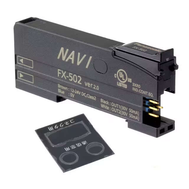
-
FX-502
Panasonic Industrial Automation Sales
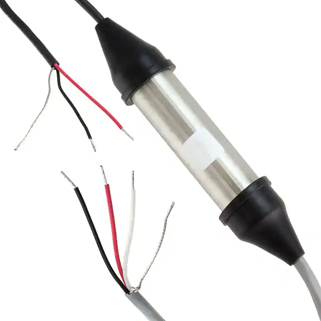
-
ASTC0000
Red Lion Controls
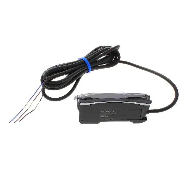
-
E3X-HD11 2M
Omron Automation and Safety
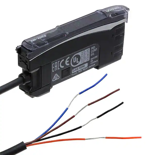
-
E3NX-MA11
Omron Automation and Safety
-
ESPICO-ALL
PalmSens BV
Tech Hub

A practical engineering guide to 3.3V and 5V logic compatibility, input thresholds, resistor dividers, translator ICs, MOSFET level shifting, I2C pull-ups, timing limits and power-sequencing risks.

The 74HC595 uses push-pull logic outputs, while the TPIC6B595 uses 50 V open-drain DMOS sinks for higher-power loads. This guide compares timing, current limits, 3.3 V interfacing, load wiring, thermal…

The 74HC595 converts serial data into eight stable parallel outputs. This guide covers pin functions, shift and storage timing, OE and MR behavior, drive-current limits, cascading, voltage compatibilit…

A technical comparison of level-sensitive latches and edge-triggered flip-flops, covering timing windows, setup and hold limits, master–slave operation, time borrowing, race-through, HDL inference and…

A D latch stores one bit while Enable controls when data can pass. This reference covers gate-level operation, truth tables, transparency, setup and hold timing, LE versus OE, common ICs and practical …

An SR latch stores one bit through cross-coupled feedback. This engineering reference covers NOR and NAND implementations, truth tables, forbidden-state recovery, gated operation, switch debouncing, fa…

Latch circuits retain one bit through feedback. This technical reference covers SR and D latches, truth tables, transparency, timing limits, latch-versus-flip-flop behavior, applications and common log…

An engineering guide to LED driver operation, constant-current and constant-voltage outputs, linear and switching topologies, dimming, IC selection, calculations, replacement compatibility, and fault c…

Operational amplifier guide covering op amp basics, feedback, ideal vs real op amps, common configurations, buffer circuits, offset, bias current, gain-bandwidth, slew rate, rail-to-rail limits and sel…

Jumper cables guide covering safe connection order, red and black clamp placement, final ground connection, cable gauge, length, clamp quality, copper vs CCA cables, jump starter comparison and battery…


