
 My Inquiry
 My Account


NXP Semiconductors MC33CD1030AE
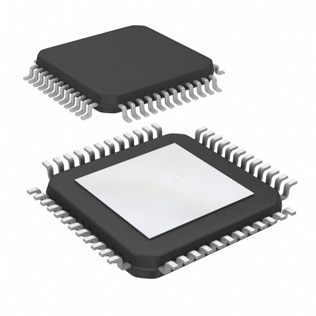
- Part No.:
- MC33CD1030AE
- Manufacturer:
- NXP Semiconductors
- Category:
- Specialized
- Package:
- 48-LQFP Exposed Pad
- Datasheet:
-
 MC33CD1030AE.pdf
- Description:
- IC INTERFACE SPECIALIZED 48LQFP
- Quantity:
- Payment:

- Shipping:

Inventory:3,563
Please send an inquiry. Send us your inquiry, and we will respond immediately.
Product details
Overview
MC33CD1030AE from NXP Semiconductors is a 33-channel SMARTMOS switch detection interface IC designed for automotive and industrial control panels. It detects open/closed states of up to 21 switch-to-ground (SG) and 12 programmable switch (SP) inputs, reports status via SPI, and provides analog multiplexed battery voltage (÷6), die temperature, and channel sensing on AMUX. It operates from 4.5 V to 36 V with programmable wetting currents (2–20 mA) and supports Normal, Low-power (50 μA IBATP), and Polling modes.
For engineers reviewing the MC33CD1030AE datasheet, MC33CD1030AE pinout, MC33CD1030AE application, or MC33CD1030AE equivalent, this page delivers verified functional identity, LQFP-48 package mapping, SPI-integrated switch monitoring architecture, wetting current configuration logic, and validated automotive-grade fault handling including overvoltage (40 V), undervoltage lockout (~4.3 V), and thermal protection (155 °C).
Technical Context
The MC33CD1030AE integrates dual oscillators (4.0 MHz for Normal mode, 192 kHz for Low-power mode) to drive configurable polling and interrupt timers. Its input stage uses a fixed 4.0 V comparator threshold with hysteresis for SG/SP state detection, while supporting ±1.0 V to 36 V input voltage range and reverse-battery survivability without external diodes on SG/SP pins.
It implements a hierarchical power architecture: VBATP powers internal regulators and SG/SP current sources, while VDDQ (3.3 V/5.0 V) supplies SPI I/O buffers and AMUX output drivers. Wake-up events-including switch state change, INT_B/CS_B/WAKE_B falling edges, and timer expiry-trigger transition from Low-power mode to Normal mode with controlled sustain current (2.0 mA, 416 μs) before wetting current activation.
Key Specifications
| Parameter | Value and Actual Design Meaning |
|---|---|
| Supply Voltage Range | 4.5 V to 36 V VBATP; functional down to 4.5 V, full parametrics from 6.0 V to 28 V |
| Switch Channels | 33 total: 21 SG-only inputs + 12 SP inputs configurable as SG or SB (switch-to-battery) |
| Wetting Current | Programmable per channel: 2.0, 6.0, 8.0, 10, 12, 14, 16, or 20 mA; pulse or continuous mode |
| Low-Power Mode Current | IBATP = 50 μA, IDDQ = 10 μA - enables ultra-low sleep-state consumption in automotive body controllers |
| SPI Interface | 3.3 V / 5.0 V compatible; CS_B, SCLK, MOSI, MISO; supports register read/write and fault reporting |
| Analog Multiplexer | 35:1 AMUX with buffered output; includes integrated ÷6 divider on SG5 for battery sensing and die temperature readout |
| Fault Protection | Overvoltage (40 V abs max), undervoltage lockout (~4.3 V), overtemperature (155 °C tLIM), SPI error, and hash fault detection |
Pinout & Package
LQFP-48 package with exposed pad (EP) recommended to be connected to system ground. Pin count and layout match JEDEC MS-026AC standard; 0.5 mm pitch; 7.0 × 7.0 mm body size.
| Pin/Terminal | Circuit Role | Design Meaning |
|---|---|---|
| SG0–SG20 | Switch-to-Ground Input | 21 dedicated pull-up current source inputs; detect closure by voltage drop below 4.0 V threshold |
| SP0–SP11 | Programmable Switch Input | 12 configurable inputs: selectable as SG (pull-up) or SB (pull-down); support wider topology flexibility |
| VBATP1 / VBATP2 | Battery Supply Input | Dual-pin battery rail connection; requires external reverse-battery protection diode |
| VDDQ | Logic Supply | 3.3 V / 5.0 V supply setting SPI I/O voltage level and AMUX driver strength |
| AMUX | Analog Multiplex Output | Buffered single-ended output carrying selected SG/SP channel, battery (÷6), or die temperature signal |
| INT_B | Interrupt Output / Wake Input | Open-drain output signaling switch state change; also accepts falling edge to wake from LPM when VDDQ is present |
| WAKE_B | Wake Control I/O | Open-drain output (low in Normal mode) or input (falling edge wakes device); supports VBATP-referenced wake-up via internal diode |
| CS_B, SCLK, MOSI, MISO | SPI Interface | Standard 4-wire SPI bus for configuration, status readback, and fault register access |
Key Features
| Feature | Design Value |
|---|---|
| Programmable Wetting Current | Eight discrete levels (2–20 mA) per channel with pulse/continuous selection - prevents contact oxidation while minimizing power and heat |
| Integrated Battery & Temp Sensing | AMUX delivers calibrated ÷6 battery voltage (via SG5) and die temperature - eliminates need for external ADC or sense resistors |
| Low-Power Mode Architecture | 50 μA IBATP with configurable polling/interrupt timers - enables multi-year battery life in always-on vehicle entry systems |
| Robust Input Protection | Withstands −1.0 V to 36 V on all SG/SP pins; reverse-battery tolerant; internal blocking diodes prevent backfeed into VBATP |
| Automotive-Grade Fault Coverage | Detects overvoltage (>36 V), undervoltage lockout, overtemperature (155 °C), SPI errors, and hash faults - supports ASIL-B system-level compliance |
Applications
| Door Control Module | Steering Wheel Switch Interface |
|---|---|
Use Scenario: Monitoring 18+ mechanical switches (lock/unlock, window, mirror) on vehicle door modules with minimal wiring harness impact. IC Role / Device Role / Timing Role: Centralized switch state acquisition and SPI-based reporting to body control module (BCM); handles wetting current sequencing during LPM wake cycles. Use Value: Reduces BCM GPIO count by 33 pins; enables <50 μA sleep current for ISO 8820-compliant quiescent draw; supports load-dump survival up to 32 V. | Use Scenario: Reading multifunction buttons (cruise, audio, phone) embedded in steering wheel assemblies exposed to wide temperature and ESD stress. IC Role / Device Role / Timing Role: High-immunity switch detector with 4.0 V comparator threshold and hysteresis; delivers stable state reporting despite vibration-induced contact bounce. Use Value: Eliminates need for external RC debouncing; withstands −40 °C to 125 °C ambient; meets ISO 10605 ESD (±25 kV air, ±20 kV contact) without external protection. |
| Roof Console Switch Panel | Seat Control Unit |
Use Scenario: Managing overhead console switches (sunroof, map lights, garage door opener) where space-constrained PCBs require high channel density. IC Role / Device Role / Timing Role: 33-channel consolidation with AMUX-enabled battery monitoring - replaces discrete comparators, muxes, and voltage dividers. Use Value: Cuts BOM cost by >40% vs. discrete solution; reduces PCB area by integrating 21 SG + 12 SP + analog sensing + fault logic in single LQFP-48. | Use Scenario: Detecting seat position memory buttons, heating/cooling controls, and lumbar adjustment switches in premium seating systems. IC Role / Device Role / Timing Role: Programmable wetting current ensures reliable contact closure detection across varying contact plating (Au, Ni, Ag) and aging profiles. Use Value: Supports 20 mA wetting for high-resistance contacts; sustains 2.0 mA for 416 μs during LPM wake to avoid inrush current spikes on shared VBATP rails. |
Equivalent & Alternatives
The following parts are listed as comparable options for similar switch detection interface applications.
| Alternative Part | Technical Difference | Application Difference | Selection Advice |
|---|---|---|---|
| MC33CD1030A | Same functionality and pinout; rated for −40 °C to 105 °C (vs. 125 °C for MC33CD1030AE) | Not qualified for under-hood or high-temp cabin locations requiring extended temperature operation | Select MC33CD1030A only for interior modules with ambient ≤105 °C; verify thermal derating for sustained 12 mA wetting current use. |
| TPS65381A-Q1 | 16-channel switch monitor with integrated 3.3 V LDO and watchdog; no AMUX or battery sensing; wetting current not programmable | Lacks analog multiplexing, battery/temperature monitoring, and fine-grained wetting control - suited for simpler, lower-channel-count systems | Choose TPS65381A-Q1 when system needs integrated power management and basic switch monitoring without analog diagnostics or extended channel count. |
Compared with MC33CD1030A, MC33CD1030AE adds 20 °C higher junction temperature rating and enhanced thermal fault handling; versus TPS65381A-Q1, it delivers 2x channel count, programmable wetting, and integrated analog sensing - making it optimal for complex, thermally demanding automotive HMI systems.
Availability
MC33CD1030AE is available at Aetrix Electronics and suitable for automotive body control modules, steering wheel interface units, roof console assemblies, and seat control systems requiring stable component supply across extended temperature ranges and long production lifecycles.
Supply support for MC33CD1030AE includes scheduled delivery planning, volume procurement assistance, BOM continuity management, traceable sourcing, and lifecycle availability coordination for OEM customers, industrial embedded developers, connected-device designers, and electronics production programs.
Manufacturer
NXP Semiconductors is a global semiconductor company headquartered in Eindhoven, Netherlands, specializing in secure connectivity solutions for automotive, industrial, and IoT applications.
The CD1030 product line was developed specifically for high-reliability automotive switch monitoring, addressing requirements for extended voltage range, low-quiescent-current sleep modes, and integrated diagnostics in body electronics and human-machine interface systems.
FAQ
What is the maximum operating voltage for MC33CD1030AE and how does it handle overvoltage conditions?
The MC33CD1030AE supports absolute maximum VBATP of 40 V. During load dump (up to ~32 V), it maintains full functionality with current sources limited to ~2.0 mA; above 32 V, wetting current is clamped but register values remain intact. External clamping is required beyond 40 V. The IC includes internal overvoltage detection that flags faults via SPI without disrupting operation.
Does MC33CD1030AE support both 3.3 V and 5.0 V MCU interfaces, and how is level compatibility achieved?
Yes, MC33CD1030AE supports both 3.3 V and 5.0 V MCU interfaces via its VDDQ pin, which sets the logic I/O voltage level for CS_B, SCLK, MOSI, MISO, and AMUX. The SPI drivers and input buffers are designed to operate correctly across this range, eliminating need for external level shifters. MISO output is actively driven, not open-drain, ensuring robust communication integrity.
How does MC33CD1030AE manage thermal safety during sustained wetting current operation?
MC33CD1030AE incorporates multiple thermal limit (tLIM) cells distributed across the die. At 155 °C, it triggers an overtemperature fault, automatically reducing wetting current to 2.0 mA while maintaining sustain current. A 15 °C hysteresis prevents cycling. A separate thermal flag activates at ~120 °C to warn the MCU of rising temperature before critical shutdown occurs - all monitored and reported via SPI registers.
Can MC33CD1030AE detect switch closures while in Low-power mode, and what is the wake-up latency?
Yes, MC33CD1030AE detects switch closures in Low-power mode using its comparator-only path. Upon closure, it initiates a 416 μs sustain current pulse, then transitions to Normal mode within ≤78 μs after WAKE_B assertion. Total wake-up latency from switch event to valid SPI communication is typically <1 ms. Polling mode can further reduce average current but adds configurable delay (e.g., 64 ms default) before detection.
What analog signals are accessible through the AMUX pin of MC33CD1030AE, and how are they selected?
The AMUX pin outputs buffered analog signals from any of the 33 SG/SP channels, battery voltage (automatically divided by six when SG5 is selected), or die temperature. Selection is controlled via SPI register writes to the AMUX control bits. Hardwire two- or three-pin selection is optional but not used in the MC33CD1030AE configuration - all routing is software-defined through the AMUXSEL register.
MC33CD1030AE Specifications
- Product attributes
- Attribute value
- Manufacturer:
- NXP Semiconductors
- Series:
- -
- Package/Case:
- 48-LQFP Exposed Pad
- Packaging:
- Tray
- Product Status:
- Active
- Applications:
- Switch Monitoring
- Interface:
- SPI
- Voltage - Supply:
- 4.5V ~ 36V
- Supplier Device Package:
- 48-HLQFP (7x7)
- Grade:
- -
- Qualification:
- -
- Mounting Type:
- Surface Mount
MC33CD1030AE FAQ
1.How can I place an order for MC33CD1030AE through Aetrix?
Please submit a Request for Quotation (RFQ) for MC33CD1030AE on Aetrix. Our sales agent will provide a competitive quotation and guide you through the order confirmation once you accept the terms.
2.Are the price and stock information for MC33CD1030AE reliable?
The price and inventory of MC33CD1030AE are updated periodically and may fluctuate due to market conditions. Stock and pricing data are typically refreshed every 24 hours. Quotation validity for MC33CD1030AE is usually 5 days.
3.What payment methods are accepted for MC33CD1030AE?
We accept Wire Transfer, PayPal, Credit Card, Western Union, MoneyGram, and Escrow for MC33CD1030AE transactions.
Note: Certain payment methods may incur a processing fee.
4.How is shipping managed for MC33CD1030AE?
MC33CD1030AE orders can be shipped via leading logistics carriers, including DHL, UPS, FedEx, TNT, or Registered Mail.
Once your MC33CD1030AE order is processed, you will receive an email with the shipment details and tracking number.
Note: Tracking information may take up to 24 hours to appear. Express delivery typically takes 3–5 business days.
5.How can I obtain technical support or documentation for MC33CD1030AE?
For technical support, including MC33CD1030AE datasheets, pinout diagrams, or application guidance, please contact our engineering support team. They can provide detailed documentation and assistance for your MC33CD1030AE requirements.
6.How does Aetrix verify that MC33CD1030AE is sourced from the original manufacturer or authorized distributors?
All MC33CD1030AE products on Aetrix are procured from qualified distributors and authorized channels. Our dedicated quality assurance team conducts strict verification, including traceability checks and, if necessary, third-party testing. This ensures that MC33CD1030AE meets industry standards.
7.What is the process for return or replacement of MC33CD1030AE?
All MC33CD1030AE units undergo pre-shipment inspection (PSI). If there is an issue with MC33CD1030AE, returns or replacements are accepted under the following conditions:
1.Quantity discrepancies, incorrect items, or visible external defects (such as breakage or corrosion), acknowledged by Aetrix.
2.The issue is reported within 90 days of delivery.
3.The MC33CD1030AE part is unused and in its original packaging.
Return procedure for MC33CD1030AE:
1.Submit a request within 90 days.
2.Obtain a Return Material Authorization (RMA) from Aetrix.
MC33CD1030AE Tags

-
NVT4857UKAZ
NXP Semiconductors

-
TCA8418RTWR
Texas Instruments

-
PCA9546APWR
Texas Instruments

-
MD0100N8-G
Microchip Technology

-
PCA9548APW,118
NXP Semiconductors

-
PCA9540BDP,118
NXP Semiconductors

-
PCA9548APWR
Texas Instruments

-
PCA9546APW,118
NXP Semiconductors

-
PTN3360DBS,518
NXP Semiconductors

-
PCA9546ABS,118
NXP Semiconductors

-
PCA9518PWR
Texas Instruments

-
PCA9545APW,118
NXP Semiconductors
Tech Hub

A practical engineering guide to 3.3V and 5V logic compatibility, input thresholds, resistor dividers, translator ICs, MOSFET level shifting, I2C pull-ups, timing limits and power-sequencing risks.

The 74HC595 uses push-pull logic outputs, while the TPIC6B595 uses 50 V open-drain DMOS sinks for higher-power loads. This guide compares timing, current limits, 3.3 V interfacing, load wiring, thermal…

The 74HC595 converts serial data into eight stable parallel outputs. This guide covers pin functions, shift and storage timing, OE and MR behavior, drive-current limits, cascading, voltage compatibilit…

A technical comparison of level-sensitive latches and edge-triggered flip-flops, covering timing windows, setup and hold limits, master–slave operation, time borrowing, race-through, HDL inference and…

A D latch stores one bit while Enable controls when data can pass. This reference covers gate-level operation, truth tables, transparency, setup and hold timing, LE versus OE, common ICs and practical …

An SR latch stores one bit through cross-coupled feedback. This engineering reference covers NOR and NAND implementations, truth tables, forbidden-state recovery, gated operation, switch debouncing, fa…

Latch circuits retain one bit through feedback. This technical reference covers SR and D latches, truth tables, transparency, timing limits, latch-versus-flip-flop behavior, applications and common log…

An engineering guide to LED driver operation, constant-current and constant-voltage outputs, linear and switching topologies, dimming, IC selection, calculations, replacement compatibility, and fault c…

Operational amplifier guide covering op amp basics, feedback, ideal vs real op amps, common configurations, buffer circuits, offset, bias current, gain-bandwidth, slew rate, rail-to-rail limits and sel…

Jumper cables guide covering safe connection order, red and black clamp placement, final ground connection, cable gauge, length, clamp quality, copper vs CCA cables, jump starter comparison and battery…


