
 My Inquiry
 My Account


NXP Semiconductors MC33HB2001EKR2
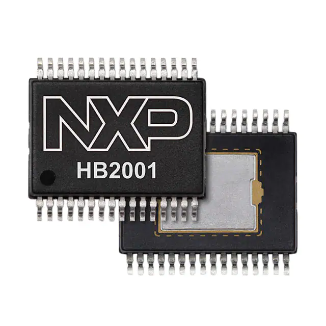
- Part No.:
- MC33HB2001EKR2
- Manufacturer:
- NXP Semiconductors
- Category:
- Motor Drivers, Controllers
- Package:
- 32-SSOP (0.295", 7.50mm Width) Exposed Pad
- Datasheet:
-
 MC33HB2001EKR2.pdf
- Description:
- IC HALF BRIDGE DRIVER 32SOIC
- Quantity:
- Payment:

- Shipping:

Inventory:4,531
Please send an inquiry. Send us your inquiry, and we will respond immediately.
Product details
Overview
MC33HB2001EKR2 from NXP Semiconductors is a SMARTMOS monolithic H-bridge power IC for brushed DC motor control, featuring SPI programmability, 10 A peak output current, 3.0 A continuous average load current, and real-time analog current feedback with <5.0 % error. It operates from 5.0 V to 28 V VPWR and is qualified to AEC-Q100 Grade 1 for automotive throttle and EGR actuator applications.
For engineers reviewing the MC33HB2001EKR2 datasheet, MC33HB2001EKR2 pinout, MC33HB2001EKR2 application, or MC33HB2001EKR2 equivalent, key selection considerations include SPI-configurable slew rates (0.25–16 V/μs), four selectable current limits (5.4/7.0/8.8/10.7 A), integrated overtemperature/short-circuit diagnostics, and ISO 26262-compliant safety architecture.
Technical Context
The MC33HB2001EKR2 implements a full H-bridge using four internal N-channel MOSFETs with RDS(on) ≤ 125 mΩ at TJ = 150 °C, enabling bidirectional PWM-controlled motor drive. Its SPI interface supports daisy-chaining and provides register-based control of slew rate, current limit, bridge configuration (H- or half-bridge), and fault register clearing.
Thermal management relies on junction-to-case thermal resistance <1.0 °C/W via the exposed pad, while diagnostics include per-output short-to-ground/VPWR detection, open-load reporting, charge pump undervoltage monitoring, and temperature warning with overtemperature shutdown - all reported via FS_B and readable through the 16-bit SPI status register.
Key Specifications
| Parameter | Value and Actual Design Meaning |
|---|---|
| Peak Output Current | 16 A transient (<5 ms), enabling robust surge handling during motor startup or stall conditions |
| Continuous Average Load Current | 3.0 A at rated thermal conditions, defining steady-state motor drive capability |
| Supply Voltage Range (VPWR) | 5.0 V to 28 V, supporting 12 V and 24 V automotive systems including start-stop operation |
| Slew Rate Options | Eight SPI-selectable values from 0.25 V/μs to >16 V/μs, balancing EMI reduction and switching loss |
| Current Limit Thresholds | Four SPI-programmable levels: 5.4 A, 7.0 A, 8.8 A, 10.7 A - matching diverse motor inrush and torque requirements |
| Current Feedback Accuracy | <5.0 % error across 2.0–10 A load range via CFB pin (1/400× high-side current) |
| Logic I/O Voltage Tolerance | I/O pins withstand up to 36 V, allowing direct connection to 24 V supply rails without level-shifting |
Pinout & Package
MC33HB2001EKR2 is packaged in a 32-pin SOICW with exposed thermal pad (EP), optimized for automotive PCB layouts requiring low-inductance power routing and efficient heat dissipation to the board.
| Pin/Terminal | Circuit Role | Design Meaning |
|---|---|---|
| ENBL (Pin 2) | Enable input | Logic HIGH activates full functionality; LOW places outputs in tri-state Sleep mode with 50 μA VPWR current |
| DIS (Pin 3) | Disable input | Logic HIGH forces outputs to tri-state Standby mode without entering Sleep, preserving logic state |
| IN1 / IN2 (Pins 4–5) | H-bridge direction control | Digital inputs determining forward/reverse motor rotation; prevent shoot-through via internal logic |
| CFB (Pin 6) | Analog current feedback | Provides ground-referenced 0.25 % of high-side load current for closed-loop torque/speed control |
| FS_B (Pin 7) | Fault status flag | Open-drain active-LOW output signaling faults (overtemp, short, OV/UV) per mask register settings |
| VPWR (Pins 8,9,24,25) | Main power supply | Must be connected together with low-impedance routing to handle up to 16 A transients and minimize voltage drop |
| OUT1 / OUT2 (Pins 10–11, 22–23) | H-bridge power outputs | Each drives one motor terminal; configured as full H-bridge or independent half-bridges via SPI |
| CS_B / SCLK / MOSI / MISO (Pins 27–31) | SPI interface | 4-wire slave interface operating up to 10 MHz; supports daisy-chaining for multi-device systems |
| EP (Exposed Pad) | Thermal & electrical ground | Must be soldered to large copper pour for <1.0 °C/W junction-to-case thermal resistance and GND integrity |
Key Features
| Feature | Design Value |
|---|---|
| SPI-configurable slew rate | Eight discrete settings (0.25–16 V/μs) enable precise EMI/noise vs. thermal trade-off without hardware change |
| Programmable current limiting | Four thresholds (5.4/7.0/8.8/10.7 A) allow dynamic adaptation to motor load profiles and battery voltage sag |
| Real-time analog current feedback | CFB pin delivers <5.0 % accurate proportional signal (1/400× HS current), usable for closed-loop control without external shunt |
| Integrated diagnostics | Detects per-output shorts (to GND/VPWR), open load, overvoltage, undervoltage, charge pump fault, and die temperature events |
| AEC-Q100 Grade 1 & ISO 26262 support | Validated for −40 °C to 125 °C ambient and −40 °C to 150 °C junction, with safety mechanisms for ASIL-B compliance |
Applications
| Electronic Throttle Control | Exhaust Gas Recirculation (EGR) |
|---|---|
Use Scenario: Precise air-fuel ratio management in gasoline engines using stepperless DC motor actuation. IC Role / Device Role / Timing Role: H-bridge driver executing PWM-based position control with real-time current feedback for torque verification. Use Value: Enables fail-safe limp-home operation via diagnostic reporting and configurable current limiting during partial failure modes. | Use Scenario: Regulating recirculated exhaust flow to reduce NOx emissions in diesel and turbocharged gasoline engines. IC Role / Device Role / Timing Role: Bidirectional motor driver controlling EGR valve position with overtemperature protection during high-exhaust-temp operation. Use Value: Maintains functional safety integrity under 150 °C junction temperatures and supports ISO 26262 ASIL-B decomposition. |
| Turbocharger Wastegate Actuation | Electric Coolant Pump Control |
Use Scenario: Adjusting turbine boost pressure by positioning wastegate flaps in turbocharged powertrains. IC Role / Device Role / Timing Role: SPI-programmable H-bridge delivering controlled torque and direction with slew-rate optimization for low EMI near sensitive sensors. Use Value: Eliminates need for external current sensing while providing diagnostic coverage for open/short faults critical to emission compliance. | Use Scenario: Variable-speed coolant circulation in electric and hybrid vehicle thermal management systems. IC Role / Device Role / Timing Role: Motor driver operating from 12 V or 48 V auxiliary supplies, leveraging wide VPWR range (5–28 V) and 36 V-tolerant I/O. Use Value: Supports start-stop duty cycles with <50 μA Sleep mode current and reverse-battery protection compatibility via external FET biasing. |
Equivalent & Alternatives
The following parts are listed as comparable options for similar H-bridge motor driver applications.
| Alternative Part | Technical Difference | Application Difference | Selection Advice |
|---|---|---|---|
| DRV3205AQPWPRQ1 | 50 V max VPWR, 3.5 A continuous, no integrated current mirror, SPI-less analog control interface | Lacks real-time analog current feedback and advanced SPI diagnostics; suited for simpler, lower-voltage systems | Select when cost-sensitive designs prioritize analog simplicity over diagnostic depth and current sensing integration |
| STSPIN32F0601TR | Integrated 64 MHz ARM Cortex-M0, 3-phase gate driver, no H-bridge power stage, requires external MOSFETs | Requires external power stage and layout effort; targets BLDC rather than brushed DC motors | Choose when system-level integration (MCU + gate driver) is preferred over monolithic power IC architecture |
Compared with DRV3205AQPWPRQ1 and STSPIN32F0601TR, the MC33HB2001EKR2 uniquely combines monolithic 10 A H-bridge power integration, SPI-configurable diagnostics, and <5.0 % accurate analog current feedback - eliminating external sensing components while meeting ASIL-B requirements out-of-the-box.
Availability
MC33HB2001EKR2 is available at Aetrix Electronics and suitable for electronic throttle control, exhaust gas recirculation (EGR), turbocharger actuation, and electric coolant pump applications requiring stable component supply, automotive-grade reliability, and long-term lifecycle support.
Supply support for MC33HB2001EKR2 includes scheduled delivery planning, volume procurement assistance, BOM continuity management, traceable sourcing, and lifecycle availability coordination for OEM customers, industrial embedded developers, connected-device designers, and electronics production programs.
Manufacturer
NXP Semiconductors is a global semiconductor leader focused on secure connectivity solutions for automotive, industrial, and IoT applications, with deep expertise in automotive-grade power management and functional safety.
The MC33HB2001EKR2 belongs to NXP's SMARTMOS automotive H-bridge product line, engineered specifically for ISO 26262-compliant brushed DC motor control in powertrain and chassis subsystems where diagnostic coverage, thermal robustness, and SPI configurability are mandatory.
FAQ
What is the maximum continuous current rating for the MC33HB2001EKR2?
The MC33HB2001EKR2 has a nominal continuous average load current rating of 3.0 A under specified thermal conditions. This value assumes proper PCB thermal design with the exposed pad soldered to a low-impedance ground plane. Peak current capability is 16 A for transients under 5 ms, enabling reliable motor startup and stall handling. The actual continuous current depends on ambient temperature, airflow, and board layout - refer to RΘJA = 23.9 °C/W (4-layer board) for thermal modeling. MC33HB2001EKR2 maintains this rating across its full −40 °C to 125 °C operating ambient range.
Does the MC33HB2001EKR2 require an external charge pump capacitor?
Yes, the MC33HB2001EKR2 requires an external 100 nF reservoir capacitor connected between the CCP pin and VPWR. This capacitor is essential for internal charge pump operation, which generates the gate drive voltage needed to fully enhance the N-channel MOSFETs. Without it, the device fails to operate correctly - outputs remain disabled and fault flags may assert. The capacitor must be placed close to the CCP and VPWR pins with low-inductance routing. MC33HB2001EKR2 datasheet Section 7.3.8 explicitly states "The part does not operate properly without the external reservoir capacitor."
How does the CFB pin provide current feedback on the MC33HB2001EKR2?
The CFB pin on the MC33HB2001EKR2 delivers a ground-referenced analog current proportional to the high-side output current at a scaling factor of 1/400 (0.25 %). This current mirror output achieves <5.0 % accuracy across a 2.0 A to 10 A load range. An external resistor (RCFB) converts the current to voltage; typical values yield ~1 V/A. Filtering is added via an external capacitor to suppress noise. When unused, CFB must be tied to GND through a resistor. MC33HB2001EKR2 uses this signal for both internal current limiting and external closed-loop control - eliminating need for external shunt resistors in many designs.
Can the MC33HB2001EKR2 operate without SPI communication?
Yes, the MC33HB2001EKR2 supports standalone operation without SPI: default settings apply - 2.0 V/μs slew rate and 7.0 A current limit threshold. All basic H-bridge functions (IN1/IN2 direction control, ENBL/DIS enable/disable) remain fully operational. SPI is optional for advanced configuration (e.g., custom slew rates, alternate current limits, half-bridge mode, diagnostic masking). The device retains full protection features (overtemperature, short-circuit, UV/OV) regardless of SPI usage. MC33HB2001EKR2 is designed for flexibility - SPI enhances diagnostics and tuning but isn't required for core motor drive functionality.
What package type is used for the MC33HB2001EKR2?
The MC33HB2001EKR2 uses a 32-pin SOICW (Small Outline Integrated Circuit with Wide body) package with an exposed thermal pad (EP). This surface-mount package measures 12.8 mm × 7.62 mm × 2.65 mm and features gull-wing leads for automated assembly. The exposed pad must be soldered to a large PCB copper area to achieve <1.0 °C/W junction-to-case thermal resistance. The "R2" suffix indicates tape-and-reel packaging for automated pick-and-place. MC33HB2001EKR2 shares pinout and footprint with the MC33HB2001EK variant, ensuring drop-in compatibility within the SOICW family.
MC33HB2001EKR2 Specifications
- Product attributes
- Attribute value
- Manufacturer:
- NXP Semiconductors
- Series:
- -
- Package/Case:
- 32-SSOP (0.295", 7.50mm Width) Exposed Pad
- Packaging:
- Tape & Reel (TR)
- Product Status:
- Active
- Motor Type - Stepper:
- -
- Motor Type - AC, DC:
- -
- Function:
- -
- Output Configuration:
- Half Bridge (2)
- Interface:
- SPI
- Technology:
- Power MOSFET
- Step Resolution:
- -
- Applications:
- DC Motors, General Purpose
- Current - Output:
- -
- Voltage - Supply:
- 5V ~ 28V
- Voltage - Load:
- 5V ~ 28V
- Operating Temperature:
- -40°C ~ 150°C (TJ)
- Grade:
- -
- Qualification:
- -
- Mounting Type:
- Surface Mount
- Supplier Device Package:
- 32-SOIC-EP
MC33HB2001EKR2 FAQ
1.How can I place an order for MC33HB2001EKR2 through Aetrix?
Please submit a Request for Quotation (RFQ) for MC33HB2001EKR2 on Aetrix. Our sales agent will provide a competitive quotation and guide you through the order confirmation once you accept the terms.
2.Are the price and stock information for MC33HB2001EKR2 reliable?
The price and inventory of MC33HB2001EKR2 are updated periodically and may fluctuate due to market conditions. Stock and pricing data are typically refreshed every 24 hours. Quotation validity for MC33HB2001EKR2 is usually 5 days.
3.What payment methods are accepted for MC33HB2001EKR2?
We accept Wire Transfer, PayPal, Credit Card, Western Union, MoneyGram, and Escrow for MC33HB2001EKR2 transactions.
Note: Certain payment methods may incur a processing fee.
4.How is shipping managed for MC33HB2001EKR2?
MC33HB2001EKR2 orders can be shipped via leading logistics carriers, including DHL, UPS, FedEx, TNT, or Registered Mail.
Once your MC33HB2001EKR2 order is processed, you will receive an email with the shipment details and tracking number.
Note: Tracking information may take up to 24 hours to appear. Express delivery typically takes 3–5 business days.
5.How can I obtain technical support or documentation for MC33HB2001EKR2?
For technical support, including MC33HB2001EKR2 datasheets, pinout diagrams, or application guidance, please contact our engineering support team. They can provide detailed documentation and assistance for your MC33HB2001EKR2 requirements.
6.How does Aetrix verify that MC33HB2001EKR2 is sourced from the original manufacturer or authorized distributors?
All MC33HB2001EKR2 products on Aetrix are procured from qualified distributors and authorized channels. Our dedicated quality assurance team conducts strict verification, including traceability checks and, if necessary, third-party testing. This ensures that MC33HB2001EKR2 meets industry standards.
7.What is the process for return or replacement of MC33HB2001EKR2?
All MC33HB2001EKR2 units undergo pre-shipment inspection (PSI). If there is an issue with MC33HB2001EKR2, returns or replacements are accepted under the following conditions:
1.Quantity discrepancies, incorrect items, or visible external defects (such as breakage or corrosion), acknowledged by Aetrix.
2.The issue is reported within 90 days of delivery.
3.The MC33HB2001EKR2 part is unused and in its original packaging.
Return procedure for MC33HB2001EKR2:
1.Submit a request within 90 days.
2.Obtain a Return Material Authorization (RMA) from Aetrix.
MC33HB2001EKR2 Tags

-
DRV2603RUNR
Texas Instruments

-
DRV8837CDSGR
Texas Instruments

-
DRV8837DSGR
Texas Instruments
-
DRV8838DSGR
Texas Instruments

-
DRV8839DSSR
Texas Instruments

-
EMC2301-1-ACZL-TR
Microchip Technology
-
DRV8231ADSGR
Texas Instruments

-
EMC2302-2-AIZL-TR
Microchip Technology

-
DRV8800PWPR
Texas Instruments
-
DRV8835DSSR
Texas Instruments

-
EMC2303-1-KP-TR
Microchip Technology

-
DRV8876PWPR
Texas Instruments
Tech Hub

A practical engineering guide to 3.3V and 5V logic compatibility, input thresholds, resistor dividers, translator ICs, MOSFET level shifting, I2C pull-ups, timing limits and power-sequencing risks.

The 74HC595 uses push-pull logic outputs, while the TPIC6B595 uses 50 V open-drain DMOS sinks for higher-power loads. This guide compares timing, current limits, 3.3 V interfacing, load wiring, thermal…

The 74HC595 converts serial data into eight stable parallel outputs. This guide covers pin functions, shift and storage timing, OE and MR behavior, drive-current limits, cascading, voltage compatibilit…

A technical comparison of level-sensitive latches and edge-triggered flip-flops, covering timing windows, setup and hold limits, master–slave operation, time borrowing, race-through, HDL inference and…

A D latch stores one bit while Enable controls when data can pass. This reference covers gate-level operation, truth tables, transparency, setup and hold timing, LE versus OE, common ICs and practical …

An SR latch stores one bit through cross-coupled feedback. This engineering reference covers NOR and NAND implementations, truth tables, forbidden-state recovery, gated operation, switch debouncing, fa…

Latch circuits retain one bit through feedback. This technical reference covers SR and D latches, truth tables, transparency, timing limits, latch-versus-flip-flop behavior, applications and common log…

An engineering guide to LED driver operation, constant-current and constant-voltage outputs, linear and switching topologies, dimming, IC selection, calculations, replacement compatibility, and fault c…

Operational amplifier guide covering op amp basics, feedback, ideal vs real op amps, common configurations, buffer circuits, offset, bias current, gain-bandwidth, slew rate, rail-to-rail limits and sel…

Jumper cables guide covering safe connection order, red and black clamp placement, final ground connection, cable gauge, length, clamp quality, copper vs CCA cables, jump starter comparison and battery…


