
 My Inquiry
 My Account


NXP Semiconductors MC44BC375UAEFR2
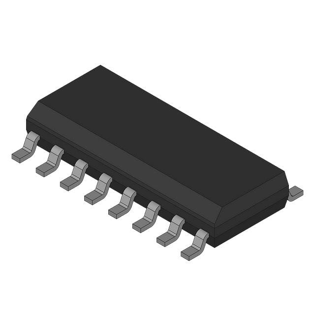
- Part No.:
- MC44BC375UAEFR2
- Manufacturer:
- NXP Semiconductors
- Category:
- Video Processing
- Package:
- 16-SOIC (0.154", 3.90mm Width)
- Datasheet:
-
 MC44BC375UAEFR2.pdf
- Description:
- IC VIDEO MODULATOR 16SOIC
- Quantity:
- Payment:

- Shipping:

Inventory:4,917
Please send an inquiry. Send us your inquiry, and we will respond immediately.
Product details
Overview
MC44BC375UAEFR2 from Freescale Semiconductor is a PLL-tuned VHF audio/video modulator IC for CH3/CH4 broadcast channels (Americas), integrating UHF oscillator, VHF divider, sound subcarrier generator, and envelope modulator in a single SO16NB package. It delivers 76 dBµV RF output level, supports 4.5 MHz or 5.5 MHz sound subcarrier selection via SFS pin, enables 14 dB or 16 dB picture-to-sound carrier ratio via PSS pin, and operates from 4.5 V to 5.5 V supply with 47 mA typical active current. It targets VCRs and set-top boxes requiring fully integrated analog TV modulation.
For engineers reviewing the MC44BC375UAEFR2 datasheet, MC44BC375UAEFR2 pinout, MC44BC375UAEFR2 application, or MC44BC375UAEFR2 equivalent, key selection considerations include channel-specific VHF divider ratio (8 for CH3/CH4), integrated 4 MHz crystal-based PLL reference, programmable power-save mode with logic output port (LOP), peak-white clipping, and absence of external varicaps or tank components.
Technical Context
The MC44BC375UAEFR2 implements a dual-loop PLL architecture: a UHF oscillator (divided by 8 for VHF output) locked to a 4 MHz crystal via a /128 reference divider yielding 31.25 kHz, and a separate sound PLL generating 4.5 MHz or 5.5 MHz subcarriers. Both loops use charge-pump phase-frequency detectors with externally filtered loop responses (PLLFLT and SPLFLT pins).
Modulation is performed via analog envelope modulation - video input (1 Vp-p, AC-coupled, clamped sync tip) drives a peak-white clipped modulator stage, while audio (pre-emphasis enabled) feeds an FM modulator. The device includes dedicated LOP open-collector output (15 mA sink capability) for antenna switching and transient output inhibit (263 ms delay at power-on to prevent spurious emissions during PLL lock).
Key Specifications
| Parameter | Value and Actual Design Meaning |
|---|---|
| Supply Voltage | 4.5 V to 5.5 V - ensures compatibility with standard 5 V logic rails and stable operation across industrial temperature range. |
| RF Output Level | 76 dBµV typical into 75 Ω - meets broadcast-level signal strength requirements without external amplification. |
| VHF Channel Support | CH3 = 61.25 MHz, CH4 = 67.25 MHz - fixed VHF divider ratio of 8 enables direct Americas-band VCR/set-top box deployment. |
| Sound Subcarrier | Selectable 4.5 MHz or 5.5 MHz via SFS pin - supports NTSC-M and PAL-B/G standards without external oscillators. |
| Picture-to-Sound Ratio | 14 dB or 16 dB selectable via PSS pin - matches regional broadcast specifications and simplifies system-level alignment. |
| Power Save Current | 5 mA typical - reduces standby consumption by >90% vs active mode, enabling low-power remote-controlled devices. |
| ESD Protection | HBM ≥ 4 kV - exceeds IEC 61000-4-2 Level 3, enhancing robustness in consumer assembly and field environments. |
Pinout & Package
MC44BC375UAEFR2 is housed in a 16-pin SO16NB (Small Outline Integrated Circuit, narrow body) package per JEDEC MS-012, with 1.27 mm pitch, 10.0 mm × 6.2 mm body size, and exposed pad not present. Pin 1 is marked by a dot/dimple adjacent to sprocket holes on tape-and-reel packaging (R2 suffix).
| Pin/Terminal | Circuit Role | Design Meaning |
|---|---|---|
| 1 CHS | Channel Select Input | Logic HI selects CH4 (67.25 MHz); LO selects CH3 (61.25 MHz) - eliminates external DIP switches or jumpers. |
| 2 PSS | Picture-to-Sound Ratio Control | HI sets 16 dB ratio; LO sets 14 dB - directly configures intercarrier spacing per regional broadcast standard. |
| 3 LOP | Logic Output Port | Open-collector output sinking up to 15 mA - drives antenna switch or attenuator without external transistor. |
| 4 XTAL | Crystal Oscillator Input | Accepts 4 MHz fundamental-mode crystal - provides stable PLL reference without external capacitors or buffer. |
| 5 GND | Analog Ground | Dedicated ground return for video/audio sections - minimizes noise coupling into sensitive modulation paths. |
| 6 PREEM | Pre-emphasis Capacitor Terminal | Connects external capacitor (470 pF for B/G, 750 pF for M/N) - sets audio pre-emphasis time constant (50 µs or 75 µs). |
| 7 AUDIO | Audio Input | AC-coupled, 55 kΩ typical input impedance - accepts line-level audio with built-in pre-emphasis filtering. |
| 8 SPLFLT | Sound PLL Loop Filter | External RC network sets sound PLL bandwidth and stability - decouples sound carrier generation from video path. |
| 9 PSave/LO | Power Save & LOP Enable | LO activates standby mode (disables VCOs/mixers) and forces LOP low - single-pin control of both power and switching logic. |
| 10 VIDEO | Video Input | AC-coupled, 500 kΩ input impedance, sync-tip clamped - accepts 1 Vp-p composite video with automatic black-level restoration. |
| 11 VCCA | Analog Power Supply | Primary 5 V supply for modulator core - must be applied simultaneously with TVOVCC to ensure proper biasing. |
| 12 GND | Digital Ground | Separate ground for PLL and logic sections - prevents digital switching noise from modulating RF output. |
| 13 TVOUT | Modulated RF Output | 75 Ω matched output delivering VHF AM/FM composite signal - connects directly to coaxial antenna interface. |
| 14 TVOVCC | Output Stage Power Supply | Secondary 5 V rail for RF output driver - isolated to maintain output linearity under varying load conditions. |
| 15 PLLFLT | UHF PLL Loop Filter | External RC network sets UHF PLL lock time and jitter performance - critical for clean channel synthesis and low spurs. |
| 16 SFS | Sound Frequency Select | HI selects 5.5 MHz; LO selects 4.5 MHz - configures sound subcarrier to match video standard without hardware change. |
Key Features
| Feature | Design Value |
|---|---|
| Integrated PLL with 4 MHz crystal reference | Eliminates external tank circuits, varicaps, and inductors - reduces BOM count by ≥7 passive components and PCB area by >30 mm². |
| Programmable picture-to-sound carrier ratio | 14 dB or 16 dB selection via PSS pin - avoids manual trimmer adjustment and enables firmware-driven regional compliance. |
| Peak white clip circuit | Soft-clips video waveform above 1.4 VCBVS - prevents overmodulation-induced distortion and adjacent-channel interference. |
| Transient output inhibit | 263 ms blanking period after power-on or wake-up - suppresses PLL lock transients that would otherwise radiate spurious energy. |
| Logic Output Port (LOP) | Open-collector output with 15 mA sink - directly controls RF antenna switches without level-shifting or buffering circuitry. |
Applications
| VCR Video Modulation | Set-Top Box RF Modulation |
|---|---|
|
Use Scenario: Converting baseband AV signals from tuner or decoder into broadcast-compatible VHF RF output for connection to legacy TVs. IC Role / Device Role / Timing Role: Envelope modulator generating CH3/CH4 composite RF signal with synchronized audio/video carriers and precise intercarrier ratio. Use Value: Enables single-chip replacement of discrete modulator + PLL + oscillator designs, reducing cost and improving channel selectivity and spectral purity. |
Use Scenario: Adding analog RF output capability to digital set-top boxes for compatibility with older television sets lacking HDMI or composite inputs. IC Role / Device Role / Timing Role: Integrated VHF modulator with programmable channel and sound standard support, driven by microcontroller GPIOs. Use Value: Eliminates need for external crystal oscillator, sound subcarrier generator, and RF filter networks - accelerates time-to-market for CE products. |
| Home Audio/Video Recorder | Legacy Broadcast Equipment |
|
Use Scenario: Recording live TV broadcasts onto VHS tapes with full fidelity, including closed captioning and stereo audio where supported. IC Role / Device Role / Timing Role: High-fidelity analog modulator with 49 dB unweighted video SNR and <±5° differential phase - preserves color accuracy and luminance detail. Use Value: Maintains broadcast-grade signal integrity across tape generations without requiring external calibration or alignment tools. |
Use Scenario: Retrofitting aging broadcast infrastructure (e.g., hotel distribution systems, CCTV headends) with modern, reliable modulation. IC Role / Device Role / Timing Role: Drop-in replacement for obsolete discrete modulator modules, leveraging same SO16 footprint and pinout. Use Value: Restores functionality without redesigning PCBs or requalifying mechanical enclosures - extends equipment service life by 5+ years. |
Equivalent & Alternatives
The following parts are listed as comparable options for similar VHF analog TV modulator applications.
| Alternative Part | Technical Difference | Application Difference | Selection Advice |
|---|---|---|---|
| MC44BC374UAEFR2 | Lacks integrated sound subcarrier oscillator; requires external 4.5/5.5 MHz source. Same CH3/CH4 VHF support and SO16NB package. | Suitable only when external sound oscillator is already present; adds complexity and board space. | Select MC44BC374UAEFR2 only if existing design uses discrete sound generation and modulator reuse is prioritized over integration. |
| SA606DK/01 | Single-conversion mixer + IF amplifier; no video/audio modulation, no PLL, no RF output stage - requires full external modulator chain. | Used in receiver front-ends, not transmitters; cannot replace MC44BC375UAEFR2's end-to-end modulation function. | Not a functional alternative; only relevant for RF subsystem partitioning studies, not direct substitution. |
Compared with MC44BC375UAEFR2, MC44BC374UAEFR2 sacrifices sound integration for marginally lower cost but increases BOM and layout effort, while SA606DK/01 serves entirely different signal-chain roles and cannot fulfill the modulator function - making MC44BC375UAEFR2 the sole production-ready integrated solution for CH3/CH4 VCR and STB applications.
Availability
MC44BC375UAEFR2 is available at Aetrix Electronics and suitable for VCRs, set-top boxes, and home AV recorders requiring stable component supply, long-lifecycle support, and guaranteed traceability for consumer electronics manufacturing.
Supply support for MC44BC375UAEFR2 includes scheduled delivery planning, volume procurement assistance, BOM continuity management, traceable sourcing, and lifecycle availability coordination for OEM customers, industrial embedded developers, connected-device designers, and electronics production programs.
Manufacturer
Freescale Semiconductor (now part of NXP Semiconductors) is a fabless semiconductor company specializing in analog, mixed-signal, and RF solutions for automotive, industrial, and consumer markets.
The MC44BC375UAEFR2 belongs to Freescale's legacy broadcast modulator product line, designed specifically for cost-sensitive, high-volume analog TV equipment requiring fully integrated, crystal-referenced VHF modulation with minimal external components.
FAQ
What is the operating temperature range for the MC44BC375UAEFR2?
The MC44BC375UAEFR2 is rated for operation from –20°C to +85°C ambient temperature. This industrial-grade range supports deployment in consumer electronics such as VCRs and set-top boxes that may experience elevated internal temperatures during extended playback or recording sessions. The device's thermal resistance (RthJA) is 140°C/W, requiring appropriate PCB copper pour and airflow management for sustained full-load operation.
Does the MC44BC375UAEFR2 require external tuning components for VHF channel synthesis?
No, the MC44BC375UAEFR2 does not require external tuning components for VHF channel synthesis. Its integrated PLL uses a 4 MHz crystal and on-die UHF oscillator divided by 8 to generate CH3 (61.25 MHz) or CH4 (67.25 MHz) frequencies. No external varicaps, inductors, or tank circuits are needed - eliminating manual alignment and improving production yield and long-term stability.
How is the sound subcarrier frequency selected on the MC44BC375UAEFR2?
The sound subcarrier frequency on the MC44BC375UAEFR2 is selected via the SFS pin (Pin 16): applying logic HIGH yields 5.5 MHz (for PAL-B/G), while logic LOW yields 4.5 MHz (for NTSC-M). This selection is implemented using an on-chip multivibrator oscillator with internal low-pass filtering, ensuring low harmonic content (<–65 dBc) without external crystal or LC networks.
What is the purpose of the PSave/LO pin (Pin 9) on the MC44BC375UAEFR2?
The PSave/LO pin (Pin 9) on the MC44BC375UAEFR2 serves dual functions: driving the device into power-save mode (disabling internal VCOs, mixers, and modulators) when pulled LOW, and controlling the Logic Output Port (LOP) state. In power-save mode, LOP is automatically forced LOW to drive external antenna switches - enabling single-pin control of both low-power operation and RF path selection.
Can the MC44BC375UAEFR2 be used for CH1 or CH2 VHF channels?
No, the MC44BC375UAEFR2 is specifically configured for CH3 and CH4 (Americas band) and cannot be used for CH1 or CH2. Those channels are supported only by the MC44BC375JD variant (Japan band), which uses a different VHF divider ratio (6 instead of 8) and distinct pin behavior on CHS. Using MC44BC375UAEFR2 for CH1/CH2 would result in incorrect output frequency and failed regulatory compliance.
MC44BC375UAEFR2 Specifications
- Product attributes
- Attribute value
- Manufacturer:
- NXP Semiconductors
- Series:
- -
- Package/Case:
- 16-SOIC (0.154", 3.90mm Width)
- Packaging:
- Tape & Reel (TR)
- Product Status:
- Obsolete
- Function:
- Modulator
- Applications:
- Consumer Video
- Standards:
- NTSC
- Control Interface:
- -
- Voltage - Supply:
- 4.5V ~ 5.5V
- Mounting Type:
- Surface Mount
- Grade:
- -
- Qualification:
- -
- Supplier Device Package:
- 16-SOIC
MC44BC375UAEFR2 FAQ
1.How can I place an order for MC44BC375UAEFR2 through Aetrix?
Please submit a Request for Quotation (RFQ) for MC44BC375UAEFR2 on Aetrix. Our sales agent will provide a competitive quotation and guide you through the order confirmation once you accept the terms.
2.Are the price and stock information for MC44BC375UAEFR2 reliable?
The price and inventory of MC44BC375UAEFR2 are updated periodically and may fluctuate due to market conditions. Stock and pricing data are typically refreshed every 24 hours. Quotation validity for MC44BC375UAEFR2 is usually 5 days.
3.What payment methods are accepted for MC44BC375UAEFR2?
We accept Wire Transfer, PayPal, Credit Card, Western Union, MoneyGram, and Escrow for MC44BC375UAEFR2 transactions.
Note: Certain payment methods may incur a processing fee.
4.How is shipping managed for MC44BC375UAEFR2?
MC44BC375UAEFR2 orders can be shipped via leading logistics carriers, including DHL, UPS, FedEx, TNT, or Registered Mail.
Once your MC44BC375UAEFR2 order is processed, you will receive an email with the shipment details and tracking number.
Note: Tracking information may take up to 24 hours to appear. Express delivery typically takes 3–5 business days.
5.How can I obtain technical support or documentation for MC44BC375UAEFR2?
For technical support, including MC44BC375UAEFR2 datasheets, pinout diagrams, or application guidance, please contact our engineering support team. They can provide detailed documentation and assistance for your MC44BC375UAEFR2 requirements.
6.How does Aetrix verify that MC44BC375UAEFR2 is sourced from the original manufacturer or authorized distributors?
All MC44BC375UAEFR2 products on Aetrix are procured from qualified distributors and authorized channels. Our dedicated quality assurance team conducts strict verification, including traceability checks and, if necessary, third-party testing. This ensures that MC44BC375UAEFR2 meets industry standards.
7.What is the process for return or replacement of MC44BC375UAEFR2?
All MC44BC375UAEFR2 units undergo pre-shipment inspection (PSI). If there is an issue with MC44BC375UAEFR2, returns or replacements are accepted under the following conditions:
1.Quantity discrepancies, incorrect items, or visible external defects (such as breakage or corrosion), acknowledged by Aetrix.
2.The issue is reported within 90 days of delivery.
3.The MC44BC375UAEFR2 part is unused and in its original packaging.
Return procedure for MC44BC375UAEFR2:
1.Submit a request within 90 days.
2.Obtain a Return Material Authorization (RMA) from Aetrix.
MC44BC375UAEFR2 Tags
-
HDMI2C1-6C1
STMicroelectronics
-
ADA4430-1YKSZ-R7
Analog Devices Inc.

-
LM1881MX/NOPB
Texas Instruments

-
SN75DP130SSRGZR
Texas Instruments
-
EQCO30T5.2
Microchip Technology

-
LMH1980MM/NOPB
Texas Instruments
-
EQCO30R5.D
Microchip Technology

-
SII9022ACNU
Lattice Semiconductor Corporation
-
SN65DP159RGZR
Texas Instruments

-
SN65DP159RSBR
Texas Instruments
-
SN65DP141RLJR
Texas Instruments
-
LMH0303SQ/NOPB
Texas Instruments
Tech Hub

A practical engineering guide to 3.3V and 5V logic compatibility, input thresholds, resistor dividers, translator ICs, MOSFET level shifting, I2C pull-ups, timing limits and power-sequencing risks.

The 74HC595 uses push-pull logic outputs, while the TPIC6B595 uses 50 V open-drain DMOS sinks for higher-power loads. This guide compares timing, current limits, 3.3 V interfacing, load wiring, thermal…

The 74HC595 converts serial data into eight stable parallel outputs. This guide covers pin functions, shift and storage timing, OE and MR behavior, drive-current limits, cascading, voltage compatibilit…

A technical comparison of level-sensitive latches and edge-triggered flip-flops, covering timing windows, setup and hold limits, master–slave operation, time borrowing, race-through, HDL inference and…

A D latch stores one bit while Enable controls when data can pass. This reference covers gate-level operation, truth tables, transparency, setup and hold timing, LE versus OE, common ICs and practical …

An SR latch stores one bit through cross-coupled feedback. This engineering reference covers NOR and NAND implementations, truth tables, forbidden-state recovery, gated operation, switch debouncing, fa…

Latch circuits retain one bit through feedback. This technical reference covers SR and D latches, truth tables, transparency, timing limits, latch-versus-flip-flop behavior, applications and common log…

An engineering guide to LED driver operation, constant-current and constant-voltage outputs, linear and switching topologies, dimming, IC selection, calculations, replacement compatibility, and fault c…

Operational amplifier guide covering op amp basics, feedback, ideal vs real op amps, common configurations, buffer circuits, offset, bias current, gain-bandwidth, slew rate, rail-to-rail limits and sel…

Jumper cables guide covering safe connection order, red and black clamp placement, final ground connection, cable gauge, length, clamp quality, copper vs CCA cables, jump starter comparison and battery…


