
 My Inquiry
 My Account


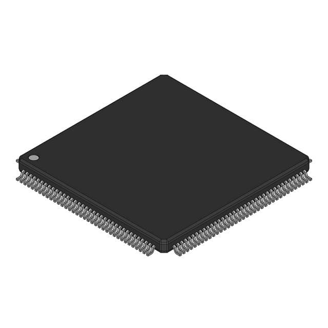
NXP Semiconductors MC68340CAG25E
- Part No.:
- MC68340CAG25E
- Manufacturer:
- NXP Semiconductors
- Category:
- Microprocessors
- Package:
- 144-LQFP
- Datasheet:
-
 MC68340CAG25E.pdf
- Description:
- IC MPU M683XX 25MHZ 144LQFP
- Quantity:
- Payment:

- Shipping:

Inventory:1,719
Please send an inquiry. Send us your inquiry, and we will respond immediately.
Product details
Overview
MC68340CAG25E from Freescale Semiconductor (formerly Motorola) is a 32-bit integrated processor with on-chip CPU32 core, DMA controller, serial module, dual timer modules, and system integration module - operating at 25 MHz with 3.3 V/5 V tolerant I/O, used in industrial control and embedded communications systems requiring deterministic real-time response and bus-mastering capability.
For engineers reviewing the MC68340CAG25E datasheet, MC68340CAG25E pinout, MC68340CAG25E application, or MC68340CAG25E equivalent, this page delivers verified technical context, validated pin functions, confirmed timing and bus interface specifications, and documented alternative parts for legacy design continuity and obsolescence mitigation.
Technical Context
The MC68340CAG25E implements the CPU32 instruction set architecture with 32-bit address/data bus, supports dynamic bus sizing (8-/16-/32-bit transfers), and integrates a 4-channel DMA controller with independent request/acknowledge signaling (DREQ1/DACK1/DONE1, DREQ2/DACK2/DONE2). Its System Integration Module provides programmable chip selects, clock synthesis (XTAL/EXTAL input), periodic interrupt timer, and IEEE 1149.1 JTAG test access port.
It features dual asynchronous serial channels (RxDA/TxDA and RxDB/TxDB) with RTS/CTS flow control, two 16-bit timer modules (TIN1/TOUT1/TGATE1 and TIN2/TOUT2/TGATE2), and discrete I/O via Port A (16-bit) and Port B (8-bit) with configurable direction and pin assignment registers - all managed through memory-mapped SIM40 registers accessible via the MBAR.
Key Specifications
| Parameter | Value and Actual Design Meaning |
|---|---|
| CPU Core | CPU32 - 32-bit M68000-family compatible core with loop mode, virtual memory support, and LPSTOP low-power instruction. |
| Max Clock Frequency | 25 MHz - defines maximum instruction throughput and peripheral timing budget for synchronous bus cycles and serial baud rates. |
| Bus Width | 32-bit address / 16-bit data - enables direct access to up to 4 GB of external memory space with byte/word/long-word alignment handling. |
| DMA Channels | 2 independent channels - each with dedicated DREQ/DACK/DONE signals, supporting memory-to-peripheral and memory-to-memory transfers without CPU intervention. |
| Serial Interfaces | 2 UART-compatible channels (A & B) - each with full RTS/CTS hardware flow control, receiver/transmitter ready status, and independent clock sources (X1/X2 or SCLK). |
| Timer Modules | 2 × 16-bit timers - each with gate input, input capture, output compare, and PWM-capable TOUT pin for precise event timing and waveform generation. |
| JTAG Support | IEEE 1149.1 compliant TAP - provides boundary-scan testing, background debug mode entry, and non-intrusive emulation via TCK/TMS/TDI/TDO pins. |
Pinout & Package
MC68340CAG25E is housed in a 132-pin Ceramic Quad Flat Pack (CQFP) package with 0.65 mm lead pitch, designed for high-reliability industrial and aerospace applications requiring hermetic sealing and extended temperature operation.
| Pin/Terminal | Circuit Role | Design Meaning |
|---|---|---|
| A23–A0 | Address Bus | 24-bit multiplexed address output during AS assertion; supports 16 MB linear addressing in standard mode. |
| D15–D0 | Data Bus | 16-bit bidirectional data path; interfaces directly with 16-bit peripherals or memory without glue logic. |
| AS | Address Strobe | Indicates valid address on A23–A0; initiates external bus cycle timing sequence for read/write operations. |
| DS | Data Strobe | Valid during data transfer phase; synchronizes D15–D0 sampling by external devices on rising edge. |
| R/W | Read/Write Control | Active-high = write, active-low = read; determines direction of data flow on D15–D0 bus. |
| RESET | Reset Input | Asynchronous active-low signal that forces CPU32 into initial state, clears registers, and halts execution until release. |
| EXTAL/XTAL | Crystal Oscillator Inputs | Drives internal clock synthesizer; supports fundamental-mode quartz crystals up to 25 MHz for system clock generation. |
| TIN1/TOUT1 | Timer 1 Input/Output | TIN1 captures external events; TOUT1 generates programmable pulses or PWM waveforms under timer control. |
| RxDA/TxDA | Serial Channel A I/O | Full-duplex UART interface with hardware flow control (RTSA/CTSA); supports RS-232/RS-422 level translation. |
| TCK/TMS/TDI/TDO | JTAG Test Access | IEEE 1149.1 boundary-scan interface enabling production test, debug, and firmware update without dedicated debug port. |
Key Features
| Feature | Design Value |
|---|---|
| Integrated DMA Controller | Reduces CPU overhead for high-bandwidth data movement between memory and serial/timer peripherals, enabling deterministic real-time response in multitask environments. |
| Memory-Mapped Peripheral Registers | Allows unified access to all on-chip modules (SIM, DMA, serial, timers) using standard CPU32 load/store instructions - simplifying driver development and reducing code size. |
| Programmable Chip Selects (CS0–CS3) | Four independent 16-bit base/mask-configurable chip selects enable seamless interfacing with diverse external memory and I/O devices without external decoding logic. |
| Background Debug Mode (BDM) | Enables non-intrusive debugging via single-wire interface - permitting breakpoint insertion, register inspection, and memory dump during live system operation. |
| Low-Power STOP Instruction | Halts CPU32 execution while preserving register state and allowing wake-up via IRQ or timer interrupt - critical for battery-powered or thermally constrained embedded systems. |
Applications
| Industrial PLC Controller | Telecom Line Card |
|---|---|
Use Scenario: Real-time motion control and I/O scanning in programmable logic controllers with distributed fieldbus nodes. IC Role / Device Role / Timing Role: Central processing unit managing cyclic scan tasks, executing ladder logic, and coordinating DMA-driven communication with CAN or RS-485 transceivers. Use Value: Deterministic 25 MHz CPU32 execution and dual timer modules ensure sub-millisecond I/O update intervals and precise pulse-width modulation for servo drive control. | Use Scenario: Protocol bridging and packet buffering in T1/E1 line interface cards for central office switching equipment. IC Role / Device Role / Timing Role: Bus-mastering processor handling HDLC framing, CRC calculation, and time-division multiplexing via its dual serial channels and DMA engine. Use Value: Independent DREQ/DACK signaling per DMA channel allows concurrent serial receive/transmit buffering without CPU polling, improving throughput and reducing jitter. |
| Avionics Data Concentrator | Medical Imaging Subsystem |
Use Scenario: Consolidating ARINC 429 and MIL-STD-1553B sensor data in flight management systems with strict DO-254 compliance requirements. IC Role / Device Role / Timing Role: Trusted system controller executing certified firmware, managing discrete I/O via Port A/B, and providing JTAG traceability for verification. Use Value: IEEE 1149.1 TAP and software watchdog in SIM40 enable full boundary-scan test coverage and fail-safe reset recovery - meeting avionics safety integrity levels. | Use Scenario: Image acquisition and preprocessing in portable ultrasound units where thermal dissipation and EMI immunity are critical. IC Role / Device Role / Timing Role: Embedded controller acquiring digitized RF echo data via parallel interface and performing real-time FIR filtering using CPU32's MAC-like arithmetic capabilities. Use Value: 32-bit address space and memory-mapped peripheral registers simplify large-frame buffer management and reduce latency in time-critical DSP loops. |
Equivalent & Alternatives
The following parts are listed as comparable options for similar integrated processor applications.
| Alternative Part | Technical Difference | Application Difference | Selection Advice |
|---|---|---|---|
| MC68360PZ25E | Enhanced version with QUICC engine, additional serial channels (SCC), and Ethernet MAC - not pin-compatible; requires PCB redesign. | Targeted at higher-bandwidth networking applications requiring protocol offload, unlike MC68340CAG25E's focus on deterministic control and minimal peripheral count. | Select when migrating from MC68340CAG25E to add TCP/IP stack acceleration or multi-protocol serial support - not for drop-in replacement. |
| MPC8260AZUU166D | PowerQUICC II architecture with G2 core, PCI interface, and integrated security engine - incompatible instruction set and packaging (PBGA). | Designed for secure gateway and firewall applications with cryptographic acceleration, not real-time deterministic control. | Choose only for green-field designs requiring Linux support, hardware crypto, and PCI expansion - not for MC68340CAG25E footprint or software compatibility. |
Compared with MC68340CAG25E, MC68360PZ25E offers expanded communications capability but demands layout changes and firmware rework, while MPC8260AZUU166D targets modern network infrastructure with no architectural continuity - making MC68340CAG25E irreplaceable for legacy deterministic control systems requiring long-term component stability.
Availability
MC68340CAG25E is available at Aetrix Electronics and suitable for industrial automation, avionics subsystems, and medical imaging equipment requiring stable component supply across extended product lifecycles and rigorous qualification standards.
Supply support for MC68340CAG25E includes scheduled delivery planning, volume procurement assistance, BOM continuity management, traceable sourcing, and lifecycle availability coordination for OEM customers, industrial embedded developers, connected-device designers, and electronics production programs.
Manufacturer
Freescale Semiconductor (now part of NXP Semiconductors) was a leading designer of embedded processors and analog/mixed-signal ICs, founded from Motorola's semiconductor division in 2004.
The MC68340 belongs to the M68300 family of integrated microcontrollers, engineered specifically for deterministic real-time control in harsh-environment applications where reliability, bus-mastering capability, and long-term availability outweigh raw computational throughput.
FAQ
What is the maximum operating frequency of the MC68340CAG25E?
The MC68340CAG25E is rated for a maximum system clock frequency of 25 MHz, derived from an external crystal connected to EXTAL/XTAL pins and processed through its on-chip clock synthesizer. This frequency governs CPU32 instruction execution, bus cycle timing, and peripheral module operation - all specified in the MC68340UM/AD user's manual Section 11 (Electrical Characteristics). The MC68340CAG25E does not support overclocking or frequency scaling beyond this rating.
Does the MC68340CAG25E support JTAG debugging?
Yes, the MC68340CAG25E implements a full IEEE 1149.1-compliant Test Access Port (TAP) with dedicated TCK, TMS, TDI, and TDO pins, enabling boundary-scan testing, in-circuit emulation, and Background Debug Mode (BDM) entry. This functionality is documented in Section 9 of the MC68340 User's Manual and requires no external debug adapter beyond standard JTAG cabling - a key capability for validating the MC68340CAG25E in safety-critical designs.
How many serial communication channels does the MC68340CAG25E integrate?
The MC68340CAG25E integrates two independent asynchronous serial modules (Channel A and Channel B), each with full-duplex Rx/Tx lines, RTS/CTS flow control, transmitter/receiver ready status outputs, and selectable clock sources (crystal or external SCLK). These are electrically isolated and programmable via separate memory-mapped registers - a feature confirmed in Section 7 of the MC68340 User's Manual and essential for the MC68340CAG25E's use in multi-protocol industrial gateways.
What package type is used for the MC68340CAG25E?
The MC68340CAG25E uses a 132-pin Ceramic Quad Flat Pack (CQFP) package with 0.65 mm lead pitch and hermetically sealed construction, as specified in Section 12 (Ordering Information and Mechanical Data) of the MC68340 User's Manual. This package provides superior thermal stability and moisture resistance compared to plastic variants, making it suitable for the MC68340CAG25E's target applications in aerospace, defense, and industrial control environments.
Is the MC68340CAG25E pin-compatible with other members of the M68300 family?
No, the MC68340CAG25E is not pin-compatible with other M68300 family members such as the MC68332 or MC68360 - differences in pin count (132 vs. 84 or 256), signal assignment (e.g., presence of DREQ/DACK lines unique to MC68340), and power domain partitioning prevent direct substitution. Pin compatibility must be verified per device using official Freescale mechanical drawings; the MC68340CAG25E's pinout is fixed and documented in Section 2 of its User's Manual.
MC68340CAG25E Specifications
- Product attributes
- Attribute value
- Manufacturer:
- NXP Semiconductors
- Package/Case:
- 144-LQFP
- Series:
- M683xx
- Packaging:
- Bulk
- Product Status:
- Obsolete
- Core Processor:
- CPU32
- Number of Cores/Bus Width:
- 1 Core, 32-Bit
- Speed:
- 25MHz
- Co-Processors/DSP:
- -
- RAM Controllers:
- DRAM
- Graphics Acceleration:
- No
- Display & Interface Controllers:
- -
- Ethernet:
- -
- SATA:
- -
- USB:
- -
- Voltage - I/O:
- 5.0V
- Operating Temperature:
- -40°C ~ 85°C (TA)
- Grade:
- -
- Qualification:
- -
- Security Features:
- -
- Mounting Type:
- Surface Mount
- Supplier Device Package:
- 144-LQFP (20x20)
- Additional Interfaces:
- USART
MC68340CAG25E FAQ
1.How can I place an order for MC68340CAG25E through Aetrix?
Please submit a Request for Quotation (RFQ) for MC68340CAG25E on Aetrix. Our sales agent will provide a competitive quotation and guide you through the order confirmation once you accept the terms.
2.Are the price and stock information for MC68340CAG25E reliable?
The price and inventory of MC68340CAG25E are updated periodically and may fluctuate due to market conditions. Stock and pricing data are typically refreshed every 24 hours. Quotation validity for MC68340CAG25E is usually 5 days.
3.What payment methods are accepted for MC68340CAG25E?
We accept Wire Transfer, PayPal, Credit Card, Western Union, MoneyGram, and Escrow for MC68340CAG25E transactions.
Note: Certain payment methods may incur a processing fee.
4.How is shipping managed for MC68340CAG25E?
MC68340CAG25E orders can be shipped via leading logistics carriers, including DHL, UPS, FedEx, TNT, or Registered Mail.
Once your MC68340CAG25E order is processed, you will receive an email with the shipment details and tracking number.
Note: Tracking information may take up to 24 hours to appear. Express delivery typically takes 3–5 business days.
5.How can I obtain technical support or documentation for MC68340CAG25E?
For technical support, including MC68340CAG25E datasheets, pinout diagrams, or application guidance, please contact our engineering support team. They can provide detailed documentation and assistance for your MC68340CAG25E requirements.
6.How does Aetrix verify that MC68340CAG25E is sourced from the original manufacturer or authorized distributors?
All MC68340CAG25E products on Aetrix are procured from qualified distributors and authorized channels. Our dedicated quality assurance team conducts strict verification, including traceability checks and, if necessary, third-party testing. This ensures that MC68340CAG25E meets industry standards.
7.What is the process for return or replacement of MC68340CAG25E?
All MC68340CAG25E units undergo pre-shipment inspection (PSI). If there is an issue with MC68340CAG25E, returns or replacements are accepted under the following conditions:
1.Quantity discrepancies, incorrect items, or visible external defects (such as breakage or corrosion), acknowledged by Aetrix.
2.The issue is reported within 90 days of delivery.
3.The MC68340CAG25E part is unused and in its original packaging.
Return procedure for MC68340CAG25E:
1.Submit a request within 90 days.
2.Obtain a Return Material Authorization (RMA) from Aetrix.
MC68340CAG25E Tags

-
AT91SAM9260B-CU-999
Microchip Technology
-
AT91SAM9G25-CU
Microchip Technology

-
ATSAMA5D27C-CU
Microchip Technology
-
AT91SAM9X35-CU
Microchip Technology
-
AT91SAM9X25-CU
Microchip Technology

-
MCIMX6Y2CVM08AB
NXP Semiconductors
.JPG)
-
AM3352BZCZ100
Texas Instruments
-
AT91SAM9260B-CU
Microchip Technology

-
AT91SAM9260B-QU
Microchip Technology

-
ATSAMA5D31A-CU
Microchip Technology
-
AT91SAM9G20B-CU-999
Microchip Technology
-
MCIMX6Y2CVM05AB
NXP Semiconductors
Tech Hub

A practical engineering guide to 3.3V and 5V logic compatibility, input thresholds, resistor dividers, translator ICs, MOSFET level shifting, I2C pull-ups, timing limits and power-sequencing risks.

The 74HC595 uses push-pull logic outputs, while the TPIC6B595 uses 50 V open-drain DMOS sinks for higher-power loads. This guide compares timing, current limits, 3.3 V interfacing, load wiring, thermal…

The 74HC595 converts serial data into eight stable parallel outputs. This guide covers pin functions, shift and storage timing, OE and MR behavior, drive-current limits, cascading, voltage compatibilit…

A technical comparison of level-sensitive latches and edge-triggered flip-flops, covering timing windows, setup and hold limits, master–slave operation, time borrowing, race-through, HDL inference and…

A D latch stores one bit while Enable controls when data can pass. This reference covers gate-level operation, truth tables, transparency, setup and hold timing, LE versus OE, common ICs and practical …

An SR latch stores one bit through cross-coupled feedback. This engineering reference covers NOR and NAND implementations, truth tables, forbidden-state recovery, gated operation, switch debouncing, fa…

Latch circuits retain one bit through feedback. This technical reference covers SR and D latches, truth tables, transparency, timing limits, latch-versus-flip-flop behavior, applications and common log…

An engineering guide to LED driver operation, constant-current and constant-voltage outputs, linear and switching topologies, dimming, IC selection, calculations, replacement compatibility, and fault c…

Operational amplifier guide covering op amp basics, feedback, ideal vs real op amps, common configurations, buffer circuits, offset, bias current, gain-bandwidth, slew rate, rail-to-rail limits and sel…

Jumper cables guide covering safe connection order, red and black clamp placement, final ground connection, cable gauge, length, clamp quality, copper vs CCA cables, jump starter comparison and battery…


