
 My Inquiry
 My Account


NXP Semiconductors MC68HC000EI10
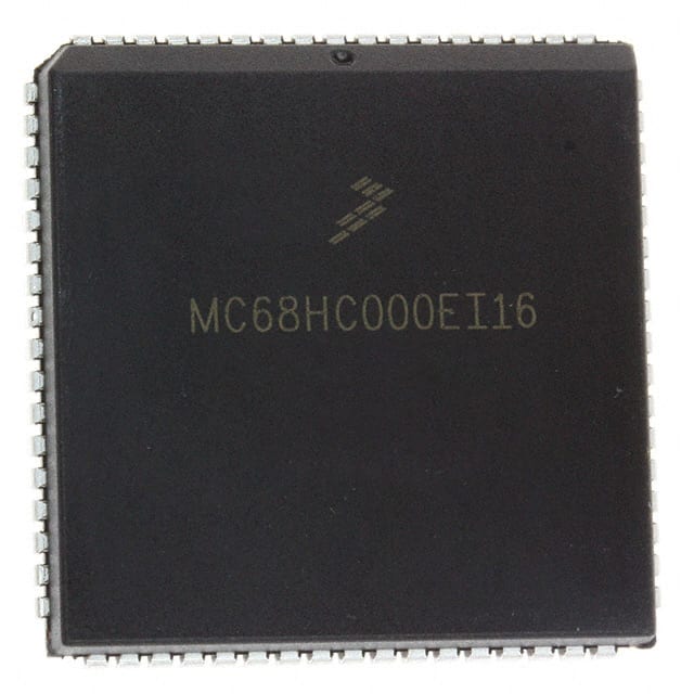
- Part No.:
- MC68HC000EI10
- Manufacturer:
- NXP Semiconductors
- Category:
- Microprocessors
- Package:
- 68-LCC (J-Lead)
- Datasheet:
-
 MC68HC000EI10.pdf
- Description:
- IC MPU M680X0 10MHZ 68PLCC
- Quantity:
- Payment:

- Shipping:

Inventory:3,039
Please send an inquiry. Send us your inquiry, and we will respond immediately.
Product details
Overview
MC68HC000EI10 from Freescale Semiconductor (formerly Motorola) is a CMOS 16/32-bit microprocessor with 32-bit internal architecture, 16-bit external data bus, and 24-bit address bus supporting up to 16 MB of memory. It operates at 10 MHz maximum clock frequency, features two privilege modes (User/Supervisor), and implements full M68000 instruction set compatibility. It was widely used in industrial controllers and embedded systems requiring deterministic real-time execution.
For engineers reviewing the MC68HC000EI10 datasheet, MC68HC000EI10 pinout, MC68HC000EI10 application, or MC68HC000EI10 equivalent, key selection considerations include its 64-pin DIP package, asynchronous bus timing with DTACK handshake, 5 V single-supply operation, and support for 8-/16-bit peripheral interfacing without external glue logic.
Technical Context
The MC68HC000EI10 implements the original M68000 architecture in high-density CMOS, reducing power consumption versus the NMOS MC68000 while maintaining binary instruction compatibility. It supports both synchronous and fully asynchronous bus protocols via programmable control signals including DTACK, BERR, and HALT.
Its exception handling includes 256 vector locations, seven priority-level interrupts, bus error recovery with retry capability, and supervisor/user mode separation enforced by status register bits. The processor uses a three-stage pipeline (fetch/decode/execute) and executes instructions in 1–512 clock cycles depending on addressing mode and operand size.
Key Specifications
| Parameter | Value and Actual Design Meaning |
|---|---|
| Max Clock Frequency | 10 MHz - defines maximum instruction throughput and system timing budget for synchronous designs. |
| Data Bus Width | 16-bit external - enables efficient access to 16-bit peripherals and memory while retaining 32-bit internal registers. |
| Address Bus Width | 24-bit - supports direct linear addressing of up to 16 MB of physical memory space. |
| Supply Voltage | 5 V ±5% - compatible with legacy TTL/CMOS logic families and standard industrial power rails. |
| Operating Temperature | −40°C to +85°C - qualified for extended industrial environments without derating. |
| Instruction Set | Fully compatible with MC68000 - ensures software portability across M68K family, including assembly and compiled code. |
| Power Dissipation | Typical 1.2 W at 10 MHz - enables passive cooling in dense embedded chassis without forced airflow. |
Pinout & Package
MC68HC000EI10 is housed in a 64-pin Dual In-Line Package (DIP), case 740-03 (L suffix), with 0.6-inch body width and 0.1-inch lead pitch. Pin layout follows standard M68000-compatible signal assignment.
| Pin/Terminal | Circuit Role | Design Meaning |
|---|---|---|
| CLK | Clock Input | Accepts TTL-compatible square wave; synchronizes all internal state transitions and bus cycles. |
| RESET | Active-Low Reset Input | Forces processor into initial state, clears registers, and begins execution at vector address $000000. |
| HALT | Active-Low Halt Request | Stops CPU execution while preserving bus state; used for low-power standby or debug halt. |
| DTACK | Direct Memory Access Acknowledge | Asynchronous handshake signal indicating memory/peripheral readiness; enables zero-wait-state operation. |
| BERR | Bus Error Output | Signals invalid address or unresponsive peripheral; triggers bus error exception vector $000028. |
| VPA | Valid Peripheral Address | Indicates current cycle targets M6800-compatible peripheral; enables automatic address decoding. |
| AS | Address Strobe | Validates address bus contents; used by external latches to capture stable address before data transfer. |
| R/W | Read/Write Control | Active-high = read, active-low = write; controls direction of data bus drivers and memory/peripheral operation. |
Key Features
| Feature | Design Value |
|---|---|
| Two-Mode Privilege Architecture | Separates user application code from kernel/system code via status register bit S, preventing unauthorized hardware access. |
| Full Asynchronous Bus Interface | Eliminates need for fixed wait states by using DTACK handshake, enabling interoperability with slow ROM, EEPROM, or custom logic. |
| 256-Vector Exception Handling | Supports prioritized interrupt servicing, precise fault recovery (bus/address errors), and trace/debug entry points. |
| M6800 Peripheral Compatibility Mode | Generates VPA and function codes to directly interface with legacy M6800-series peripherals without address translation logic. |
| Three-Stage Instruction Pipeline | Overlaps fetch, decode, and execute phases to improve average instruction throughput without speculative execution. |
Applications
| Industrial PLC Controller | Legacy Test Equipment |
|---|---|
|
Use Scenario: Real-time ladder logic scanning and I/O scanning in DIN-rail mounted programmable logic controllers. IC Role / Device Role / Timing Role: Central execution unit managing deterministic scan cycles, interrupt-driven analog input sampling, and serial HMI communication. Use Value: 10 MHz clock and predictable instruction timing enable sub-10 ms scan cycles; 24-bit addressing supports modular I/O expansion up to 16 MB. |
Use Scenario: Automated calibration and signal generation in benchtop oscilloscopes and waveform analyzers manufactured 1985–1995. IC Role / Device Role / Timing Role: Main controller coordinating ADC/DAC transfers, front-panel UI, and GPIB/IEEE-488 bus interface. Use Value: M6800 peripheral compatibility allows direct connection to legacy DAC08xx/ADC08xx chips; asynchronous bus simplifies timing with mixed-speed subsystems. |
| Medical Imaging Subsystem | Avionics Data Recorder |
|
Use Scenario: Image buffer management and display list processing in early CT/MRI console subsystems. IC Role / Device Role / Timing Role: Dedicated image data mover executing DMA-controlled memory-to-memory transfers and video list rendering. Use Value: Supervisor mode isolation prevents application crashes from corrupting critical display buffers; bus error recovery maintains system uptime during transient memory faults. |
Use Scenario: Flight data acquisition and non-volatile storage in black box recorders compliant with DO-160 environmental standards. IC Role / Device Role / Timing Role: Fault-tolerant controller managing dual-channel ARINC 429 receivers, SRAM buffering, and EEPROM logging. Use Value: −40°C to +85°C rating meets airborne temperature extremes; HALT and RESET sequencing supports controlled power-down during emergency ejection. |
Equivalent & Alternatives
The following parts are listed as comparable options for similar 16/32-bit microprocessor applications.
| Alternative Part | Technical Difference | Application Difference | Selection Advice |
|---|---|---|---|
| MC68EC000RC16 | Embedded variant with no VPA/M6800 peripheral support; 16 MHz max clock; 52-pin QFP package. | Targeted at cost-sensitive, space-constrained embedded systems without legacy peripheral requirements. | Select when M6800 compatibility is unnecessary and surface-mount assembly is required. |
| MC68000P10 | NMOS process; higher power (up to 2.5 W); same 64-pin DIP; no CMOS low-power advantage. | Suitable only where legacy NMOS board design must be preserved and thermal headroom exists. | Select only for direct replacement on existing NMOS-based PCBs with verified thermal margin. |
Compared with MC68HC000EI10, the MC68EC000RC16 trades M6800 peripheral support for smaller footprint and higher speed but requires PCB redesign, while the MC68000P10 matches pinout and function but increases power and heat dissipation significantly.
Availability
MC68HC000EI10 is available at Aetrix Electronics and suitable for industrial PLC controllers, legacy test equipment, medical imaging subsystems, and avionics data recorders requiring stable component supply and long-term obsolescence management.
Supply support for MC68HC000EI10 includes scheduled delivery planning, volume procurement assistance, BOM continuity management, traceable sourcing, and lifecycle availability coordination for OEM customers, industrial embedded developers, connected-device designers, and electronics production programs.
Manufacturer
Freescale Semiconductor (now part of NXP Semiconductors) is a former Motorola division specializing in microcontrollers, processors, and analog products for automotive, industrial, and communications markets.
The MC68HC000 belongs to the M68K family designed for high-reliability embedded control applications where instruction compatibility, deterministic timing, and long-lifecycle support are essential.
FAQ
What is the maximum operating frequency of the MC68HC000EI10?
The MC68HC000EI10 is rated for a maximum clock frequency of 10 MHz under specified voltage and temperature conditions. This value is guaranteed across the full industrial temperature range (−40°C to +85°C) and defines the upper limit for reliable instruction execution and bus timing compliance. Exceeding this frequency may result in undefined behavior or timing violations in the MC68HC000EI10.
Does the MC68HC000EI10 support the full M68000 instruction set?
Yes, the MC68HC000EI10 implements full binary and functional compatibility with the original MC68000 instruction set, including all addressing modes, privilege instructions, and exception vectors. Software written for the MC68000 runs unchanged on the MC68HC000EI10, making it a drop-in CMOS upgrade path for legacy designs.
What package type is used for the MC68HC000EI10?
The MC68HC000EI10 is packaged in a 64-pin Dual In-Line Package (DIP) with case number 740-03 (L suffix), featuring 0.6-inch body width and 0.1-inch lead pitch. This through-hole package supports prototyping, socket-based field upgrades, and legacy manufacturing processes compatible with the original MC68000.
How does the MC68HC000EI10 handle bus errors?
The MC68HC000EI10 asserts the BERR signal when an invalid address is accessed or a peripheral fails to respond within the timeout window. This triggers a bus error exception (vector $000028), pushes a stack frame containing program counter and status register, and transfers control to the designated handler-enabling graceful recovery or diagnostic logging in the MC68HC000EI10.
Is the MC68HC000EI10 compatible with M6800-series peripherals?
Yes, the MC68HC000EI10 includes dedicated M6800 peripheral interface support via the VPA (Valid Peripheral Address) signal and function code outputs. When VPA is asserted, the MC68HC000EI10 generates timing and control signals compatible with legacy M6800-family peripherals such as the MC6820 PIA and MC6850 ACIA without external address decoding logic.
MC68HC000EI10 Specifications
- Product attributes
- Attribute value
- Manufacturer:
- NXP Semiconductors
- Package/Case:
- 68-LCC (J-Lead)
- Series:
- M680x0
- Packaging:
- Tube
- Product Status:
- Obsolete
- Core Processor:
- EC000
- Number of Cores/Bus Width:
- 1 Core, 32-Bit
- Speed:
- 10MHz
- Co-Processors/DSP:
- -
- RAM Controllers:
- -
- Graphics Acceleration:
- No
- Display & Interface Controllers:
- -
- Ethernet:
- -
- SATA:
- -
- USB:
- -
- Voltage - I/O:
- 5.0V
- Operating Temperature:
- 0°C ~ 70°C (TA)
- Grade:
- -
- Qualification:
- -
- Security Features:
- -
- Mounting Type:
- Surface Mount
- Supplier Device Package:
- 68-PLCC (24.21x24.21)
- Additional Interfaces:
- -
MC68HC000EI10 FAQ
1.How can I place an order for MC68HC000EI10 through Aetrix?
Please submit a Request for Quotation (RFQ) for MC68HC000EI10 on Aetrix. Our sales agent will provide a competitive quotation and guide you through the order confirmation once you accept the terms.
2.Are the price and stock information for MC68HC000EI10 reliable?
The price and inventory of MC68HC000EI10 are updated periodically and may fluctuate due to market conditions. Stock and pricing data are typically refreshed every 24 hours. Quotation validity for MC68HC000EI10 is usually 5 days.
3.What payment methods are accepted for MC68HC000EI10?
We accept Wire Transfer, PayPal, Credit Card, Western Union, MoneyGram, and Escrow for MC68HC000EI10 transactions.
Note: Certain payment methods may incur a processing fee.
4.How is shipping managed for MC68HC000EI10?
MC68HC000EI10 orders can be shipped via leading logistics carriers, including DHL, UPS, FedEx, TNT, or Registered Mail.
Once your MC68HC000EI10 order is processed, you will receive an email with the shipment details and tracking number.
Note: Tracking information may take up to 24 hours to appear. Express delivery typically takes 3–5 business days.
5.How can I obtain technical support or documentation for MC68HC000EI10?
For technical support, including MC68HC000EI10 datasheets, pinout diagrams, or application guidance, please contact our engineering support team. They can provide detailed documentation and assistance for your MC68HC000EI10 requirements.
6.How does Aetrix verify that MC68HC000EI10 is sourced from the original manufacturer or authorized distributors?
All MC68HC000EI10 products on Aetrix are procured from qualified distributors and authorized channels. Our dedicated quality assurance team conducts strict verification, including traceability checks and, if necessary, third-party testing. This ensures that MC68HC000EI10 meets industry standards.
7.What is the process for return or replacement of MC68HC000EI10?
All MC68HC000EI10 units undergo pre-shipment inspection (PSI). If there is an issue with MC68HC000EI10, returns or replacements are accepted under the following conditions:
1.Quantity discrepancies, incorrect items, or visible external defects (such as breakage or corrosion), acknowledged by Aetrix.
2.The issue is reported within 90 days of delivery.
3.The MC68HC000EI10 part is unused and in its original packaging.
Return procedure for MC68HC000EI10:
1.Submit a request within 90 days.
2.Obtain a Return Material Authorization (RMA) from Aetrix.
MC68HC000EI10 Tags

-
AT91SAM9260B-CU-999
Microchip Technology
-
AT91SAM9G25-CU
Microchip Technology

-
ATSAMA5D27C-CU
Microchip Technology
-
AT91SAM9X35-CU
Microchip Technology
-
AT91SAM9X25-CU
Microchip Technology

-
MCIMX6Y2CVM08AB
NXP Semiconductors
.JPG)
-
AM3352BZCZ100
Texas Instruments
-
AT91SAM9260B-CU
Microchip Technology

-
AT91SAM9260B-QU
Microchip Technology

-
ATSAMA5D31A-CU
Microchip Technology
-
AT91SAM9G20B-CU-999
Microchip Technology
-
MCIMX6Y2CVM05AB
NXP Semiconductors
Tech Hub

A practical engineering guide to 3.3V and 5V logic compatibility, input thresholds, resistor dividers, translator ICs, MOSFET level shifting, I2C pull-ups, timing limits and power-sequencing risks.

The 74HC595 uses push-pull logic outputs, while the TPIC6B595 uses 50 V open-drain DMOS sinks for higher-power loads. This guide compares timing, current limits, 3.3 V interfacing, load wiring, thermal…

The 74HC595 converts serial data into eight stable parallel outputs. This guide covers pin functions, shift and storage timing, OE and MR behavior, drive-current limits, cascading, voltage compatibilit…

A technical comparison of level-sensitive latches and edge-triggered flip-flops, covering timing windows, setup and hold limits, master–slave operation, time borrowing, race-through, HDL inference and…

A D latch stores one bit while Enable controls when data can pass. This reference covers gate-level operation, truth tables, transparency, setup and hold timing, LE versus OE, common ICs and practical …

An SR latch stores one bit through cross-coupled feedback. This engineering reference covers NOR and NAND implementations, truth tables, forbidden-state recovery, gated operation, switch debouncing, fa…

Latch circuits retain one bit through feedback. This technical reference covers SR and D latches, truth tables, transparency, timing limits, latch-versus-flip-flop behavior, applications and common log…

An engineering guide to LED driver operation, constant-current and constant-voltage outputs, linear and switching topologies, dimming, IC selection, calculations, replacement compatibility, and fault c…

Operational amplifier guide covering op amp basics, feedback, ideal vs real op amps, common configurations, buffer circuits, offset, bias current, gain-bandwidth, slew rate, rail-to-rail limits and sel…

Jumper cables guide covering safe connection order, red and black clamp placement, final ground connection, cable gauge, length, clamp quality, copper vs CCA cables, jump starter comparison and battery…


