
 My Inquiry
 My Account


NXP Semiconductors MC68SEC000AA20B1
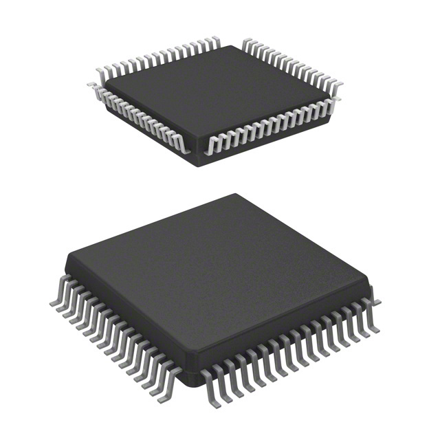
- Part No.:
- MC68SEC000AA20B1
- Manufacturer:
- NXP Semiconductors
- Category:
- Microprocessors
- Package:
- 64-QFP
- Datasheet:
-
 MC68SEC000AA20B1.pdf
- Description:
- IC MPU M680X0 20MHZ 64QFP
- Quantity:
- Payment:

- Shipping:

Inventory:4,708
Please send an inquiry. Send us your inquiry, and we will respond immediately.
Product details
Overview
MC68SEC000AA20B1 from Motorola is a static 32-bit embedded microprocessor designed for ultra-low-power battery-operated systems. It delivers 20 MHz operation at 3.3V or 5.0V, consumes only 0.5 µA in static standby mode, features a 24-bit address bus (16 MB addressing), and supports pin-for-pin replacement of the MC68EC000 in portable measuring equipment and handheld consumer devices.
For engineers reviewing the MC68SEC000AA20B1 datasheet, MC68SEC000AA20B1 pinout, MC68SEC000AA20B1 application, or MC68SEC000AA20B1 equivalent, key selection criteria include static low-power operation, 8/16-bit data bus configurability via MODE pin, object-code compatibility with the full M68000 Family, and support for interrupt-driven power management in resource-constrained embedded designs.
Technical Context
The MC68SEC000AA20B1 implements a fully static HCMOS version of the M68000 architecture with eight 32-bit data and address registers, 14 addressing modes, and memory-mapped I/O. Its bus controller handles asynchronous transfers using AS, R/W, UDS/LDS, and DTACK signals, enabling direct interfacing with off-chip peripherals without external glue logic.
Interrupt handling includes seven priority levels (IPL0–IPL2 + nonmaskable Level 7) with automatic vectoring via AVEC input, while processor status outputs FC2–FC0 indicate current execution mode (user/supervisor) and address space during active address strobes - critical for real-time OS context switching and privilege-aware firmware.
Key Specifications
| Parameter | Value and Actual Design Meaning |
|---|---|
| Core Architecture | M68000-family 32-bit static design with 24-bit address bus (16 MB linear space) |
| Clock Speed | 20 MHz maximum - enables deterministic timing for real-time control loops at fixed instruction cycle rates |
| Supply Voltage | 3.3V or 5.0V operation - allows drop-in integration into legacy 5V or modern low-voltage 3.3V systems |
| Standby Current | 0.5 µA typical at 3.3V - supports multi-year battery life in always-on sensor nodes or PDA suspend states |
| Data Bus Width | Configurable 8- or 16-bit via MODE pin - reduces PCB trace count and memory interface cost in space-constrained layouts |
| Interrupt Levels | 7 priority levels with autovectoring - simplifies ISR dispatch and eliminates software polling overhead |
| Package Type | 64-pin TQFP (10.0 mm × 10.0 mm, 0.5 mm pitch) - enables compact portable device form factors |
Pinout & Package
MC68SEC000AA20B1 is supplied in a 64-lead Thin Quad Flat Pack (TQFP) with 0.5 mm lead pitch and 10.0 mm × 10.0 mm body size - optimized for handheld and battery-powered applications requiring minimal board area.
| Pin/Terminal | Circuit Role | Design Meaning |
|---|---|---|
| A23–A0 | Address Bus (24-bit) | Unidirectional three-state outputs; A3–A1 encode interrupt level during service; supports 16 MB memory mapping |
| D15–D0 | Data Bus (16-bit) | Bidirectional three-state; width selected statically by MODE pin - enables 8-bit memory subsystems to reduce cost |
| AS, R/W, UDS, LDS, DTACK | Asynchronous Bus Control | Full handshaking protocol - eliminates need for wait-state generators when interfacing with slow peripherals or flash |
| IPL0–IPL2, AVEC | Interrupt Priority & Vectoring | Three-level encoded priority inputs + autovector enable - provides hardware-assisted ISR entry without software decoding |
| FC2–FC0 | Function Code Outputs | Indicate supervisor/user mode and address space (code/data/I/O) during AS assertion - essential for MMU-less memory protection schemes |
| CLK, RESET, HALT, MODE | System Control | External clock input; synchronous reset; halt for low-power stop-clock mode; MODE selects data bus width |
Key Features
| Feature | Design Value |
|---|---|
| Static Core Design | Enables complete clock stopping without state loss - eliminates dynamic power dissipation during idle periods |
| Pin-for-Pin Compatibility | Direct replacement for MC68EC000 in QFP/TQFP packages - allows legacy board reuse without layout changes |
| M68000 Object-Code Compatibility | Runs unmodified binaries from any M68000-family processor - preserves investment in existing firmware and toolchains |
| Configurable Data Bus | MODE pin selects 8- or 16-bit data path - matches low-cost 8-bit memories or higher-throughput 16-bit peripherals |
| Seven-Level Interrupt Architecture | Hardware priority encoding and autovectoring - reduces interrupt latency to fixed 12-cycle response time |
Applications
| Handheld Medical Instruments | Portable Test & Measurement |
|---|---|
Use Scenario: Battery-powered digital multimeters and portable oscilloscopes requiring long operational runtime between charges. IC Role / Device Role / Timing Role: Main system controller managing ADC sampling, display refresh, and user interface with deterministic interrupt response. Use Value: 0.5 µA standby current extends battery life to >2 years in sleep mode; static architecture ensures reliable wake-from-halt recovery. | Use Scenario: Field-deployable environmental sensors logging temperature, humidity, and pressure over weeks. IC Role / Device Role / Timing Role: Embedded host processor executing low-duty-cycle acquisition routines and SPI-based sensor communication. Use Value: 20 MHz clock with 16 MB addressing supports local data buffering; 3.3V operation matches lithium battery voltage profiles. |
| Consumer Electronics Remote Terminals | Industrial Human-Machine Interfaces |
Use Scenario: IR- or RF-based remote controllers for home automation systems with button-triggered wake-up. IC Role / Device Role / Timing Role: Low-power command interpreter and wireless transceiver coordinator using interrupt-driven event handling. Use Value: IPL-encoded interrupts allow prioritized processing of button presses and RF packets; MODE pin enables 8-bit flash interface to minimize BOM cost. | Use Scenario: Panel-mounted operator interfaces in factory settings requiring ESD resilience and wide temperature operation. IC Role / Device Role / Timing Role: Real-time UI controller managing touch input, serial communication with PLCs, and local alarm logic. Use Value: -40°C to +85°C rating (CPB suffix) ensures reliability in industrial enclosures; 64-pin TQFP provides robust solder joint integrity. |
Equivalent & Alternatives
The following parts are listed as comparable options for similar embedded microprocessor applications.
| Alternative Part | Technical Difference | Application Difference | Selection Advice |
|---|---|---|---|
| MC68EC000RC20 | Non-static CMOS; 20 MHz; 5V-only; higher standby current (~5 mA) | Lacks true static low-power mode - unsuitable for battery-critical applications | Select MC68SEC000AA20B1 when sub-µA sleep current and clock-stop capability are required |
| MC68332ACPV16 | Integrated QSM and TIM modules; 16 MHz; 5V; no M68000 object-code compatibility | Offers on-chip peripherals but requires full firmware rewrite - not drop-in compatible | Choose MC68SEC000AA20B1 for legacy M68000 code reuse and minimal hardware change |
Compared with MC68EC000RC20 and MC68332ACPV16, the MC68SEC000AA20B1 uniquely combines M68000 binary compatibility, sub-microamp standby, and static clock-stop - making it the only viable option for upgrading legacy 68EC000 designs to battery operation without firmware or PCB revision.
Availability
MC68SEC000AA20B1 is available at Aetrix Electronics and suitable for portable medical instruments, handheld test equipment, and battery-operated consumer electronics requiring stable component supply across extended product lifecycles.
Supply support for MC68SEC000AA20B1 includes scheduled delivery planning, volume procurement assistance, BOM continuity management, traceable sourcing, and lifecycle availability coordination for OEM customers, industrial embedded developers, connected-device designers, and electronics production programs.
Manufacturer
Motorola Semiconductor (later Freescale, now NXP) pioneered high-reliability embedded processors for industrial and communications markets, emphasizing architectural longevity and toolchain stability.
The MC68SEC000AA20B1 belongs to the M68000-family static microprocessor line, engineered specifically to extend battery life in portable embedded systems while preserving full software and hardware compatibility with the established MC68EC000 ecosystem.
FAQ
What is the operating voltage range supported by the MC68SEC000AA20B1?
The MC68SEC000AA20B1 operates across two voltage domains: 3.3V ±0.3V and 5.0V ±0.5V. This dual-voltage capability allows direct integration into both legacy 5V designs and modern low-power 3.3V systems without level-shifting circuitry. The 3.3V mode enables the 0.5 µA standby current specification, while 5V operation maintains compatibility with older peripheral ICs. Voltage selection is determined by the VCC supply rail applied during power-up.
Is the MC68SEC000AA20B1 pin-compatible with the MC68EC000?
Yes, the MC68SEC000AA20B1 is pin-for-pin compatible with the MC68EC000 in both 64-pin QFP and TQFP packages. Signal assignments, pin locations, and electrical characteristics match identically - enabling direct PCB substitution without layout modification. This compatibility extends to all control, address, data, and interrupt signals shown in the official package diagram, including AS, R/W, UDS, LDS, DTACK, IPL0–IPL2, and FC0–FC2.
Does the MC68SEC000AA20B1 support 8-bit or 16-bit data bus operation?
The MC68SEC000AA20B1 supports both 8-bit and 16-bit data bus widths, selected statically via the MODE pin at power-up. When MODE = HIGH, the processor uses D15–D0 as a full 16-bit bidirectional data bus; when MODE = LOW, it operates in 8-bit mode using D7–D0, with upper data byte transfers handled sequentially. This configurability allows optimization for cost-sensitive 8-bit memory subsystems or performance-oriented 16-bit interfaces.
What is the significance of the 'AA20B1' suffix in MC68SEC000AA20B1?
The 'AA20B1' suffix in MC68SEC000AA20B1 indicates a specific configuration: 'AA' denotes the TQFP package variant, '20' specifies 20 MHz maximum clock speed, 'B' identifies the commercial temperature grade (0°C to +70°C), and '1' reflects a particular mask revision or process iteration. This ordering code maps directly to the 'PB' suffix in Motorola's official ordering table for the 64-pin TQFP, 20 MHz, 0°C to +70°C version.
How does the MC68SEC000AA20B1 achieve ultra-low standby current?
The MC68SEC000AA20B1 achieves 0.5 µA typical standby current through its fully static HCMOS design, which eliminates dynamic power consumption by allowing the clock to be stopped indefinitely while retaining register and memory contents. Power reduction is enforced by halting the internal clock generator and disabling non-essential bias circuits - a capability confirmed in the product brief and enabled via the HALT signal. No external power gating or special sequencing is required beyond asserting HALT and maintaining VCC.
MC68SEC000AA20B1 Specifications
- Product attributes
- Attribute value
- Manufacturer:
- NXP Semiconductors
- Package/Case:
- 64-QFP
- Series:
- M680x0
- Packaging:
- Tray
- Product Status:
- Obsolete
- Core Processor:
- EC000
- Number of Cores/Bus Width:
- 1 Core, 32-Bit
- Speed:
- 20MHz
- Co-Processors/DSP:
- -
- RAM Controllers:
- -
- Graphics Acceleration:
- No
- Display & Interface Controllers:
- -
- Ethernet:
- -
- SATA:
- -
- USB:
- -
- Voltage - I/O:
- 3.3V, 5.0V
- Operating Temperature:
- 0°C ~ 70°C (TA)
- Grade:
- -
- Qualification:
- -
- Security Features:
- -
- Mounting Type:
- Surface Mount
- Supplier Device Package:
- 64-QFP (14x14)
- Additional Interfaces:
- -
MC68SEC000AA20B1 FAQ
1.How can I place an order for MC68SEC000AA20B1 through Aetrix?
Please submit a Request for Quotation (RFQ) for MC68SEC000AA20B1 on Aetrix. Our sales agent will provide a competitive quotation and guide you through the order confirmation once you accept the terms.
2.Are the price and stock information for MC68SEC000AA20B1 reliable?
The price and inventory of MC68SEC000AA20B1 are updated periodically and may fluctuate due to market conditions. Stock and pricing data are typically refreshed every 24 hours. Quotation validity for MC68SEC000AA20B1 is usually 5 days.
3.What payment methods are accepted for MC68SEC000AA20B1?
We accept Wire Transfer, PayPal, Credit Card, Western Union, MoneyGram, and Escrow for MC68SEC000AA20B1 transactions.
Note: Certain payment methods may incur a processing fee.
4.How is shipping managed for MC68SEC000AA20B1?
MC68SEC000AA20B1 orders can be shipped via leading logistics carriers, including DHL, UPS, FedEx, TNT, or Registered Mail.
Once your MC68SEC000AA20B1 order is processed, you will receive an email with the shipment details and tracking number.
Note: Tracking information may take up to 24 hours to appear. Express delivery typically takes 3–5 business days.
5.How can I obtain technical support or documentation for MC68SEC000AA20B1?
For technical support, including MC68SEC000AA20B1 datasheets, pinout diagrams, or application guidance, please contact our engineering support team. They can provide detailed documentation and assistance for your MC68SEC000AA20B1 requirements.
6.How does Aetrix verify that MC68SEC000AA20B1 is sourced from the original manufacturer or authorized distributors?
All MC68SEC000AA20B1 products on Aetrix are procured from qualified distributors and authorized channels. Our dedicated quality assurance team conducts strict verification, including traceability checks and, if necessary, third-party testing. This ensures that MC68SEC000AA20B1 meets industry standards.
7.What is the process for return or replacement of MC68SEC000AA20B1?
All MC68SEC000AA20B1 units undergo pre-shipment inspection (PSI). If there is an issue with MC68SEC000AA20B1, returns or replacements are accepted under the following conditions:
1.Quantity discrepancies, incorrect items, or visible external defects (such as breakage or corrosion), acknowledged by Aetrix.
2.The issue is reported within 90 days of delivery.
3.The MC68SEC000AA20B1 part is unused and in its original packaging.
Return procedure for MC68SEC000AA20B1:
1.Submit a request within 90 days.
2.Obtain a Return Material Authorization (RMA) from Aetrix.
MC68SEC000AA20B1 Tags

-
AT91SAM9260B-CU-999
Microchip Technology
-
AT91SAM9G25-CU
Microchip Technology

-
ATSAMA5D27C-CU
Microchip Technology
-
AT91SAM9X35-CU
Microchip Technology
-
AT91SAM9X25-CU
Microchip Technology

-
MCIMX6Y2CVM08AB
NXP Semiconductors
.JPG)
-
AM3352BZCZ100
Texas Instruments
-
AT91SAM9260B-CU
Microchip Technology

-
AT91SAM9260B-QU
Microchip Technology

-
ATSAMA5D31A-CU
Microchip Technology
-
AT91SAM9G20B-CU-999
Microchip Technology
-
MCIMX6Y2CVM05AB
NXP Semiconductors
Tech Hub

A practical engineering guide to 3.3V and 5V logic compatibility, input thresholds, resistor dividers, translator ICs, MOSFET level shifting, I2C pull-ups, timing limits and power-sequencing risks.

The 74HC595 uses push-pull logic outputs, while the TPIC6B595 uses 50 V open-drain DMOS sinks for higher-power loads. This guide compares timing, current limits, 3.3 V interfacing, load wiring, thermal…

The 74HC595 converts serial data into eight stable parallel outputs. This guide covers pin functions, shift and storage timing, OE and MR behavior, drive-current limits, cascading, voltage compatibilit…

A technical comparison of level-sensitive latches and edge-triggered flip-flops, covering timing windows, setup and hold limits, master–slave operation, time borrowing, race-through, HDL inference and…

A D latch stores one bit while Enable controls when data can pass. This reference covers gate-level operation, truth tables, transparency, setup and hold timing, LE versus OE, common ICs and practical …

An SR latch stores one bit through cross-coupled feedback. This engineering reference covers NOR and NAND implementations, truth tables, forbidden-state recovery, gated operation, switch debouncing, fa…

Latch circuits retain one bit through feedback. This technical reference covers SR and D latches, truth tables, transparency, timing limits, latch-versus-flip-flop behavior, applications and common log…

An engineering guide to LED driver operation, constant-current and constant-voltage outputs, linear and switching topologies, dimming, IC selection, calculations, replacement compatibility, and fault c…

Operational amplifier guide covering op amp basics, feedback, ideal vs real op amps, common configurations, buffer circuits, offset, bias current, gain-bandwidth, slew rate, rail-to-rail limits and sel…

Jumper cables guide covering safe connection order, red and black clamp placement, final ground connection, cable gauge, length, clamp quality, copper vs CCA cables, jump starter comparison and battery…


