
 My Inquiry
 My Account


NXP Semiconductors MCF5475ZP266
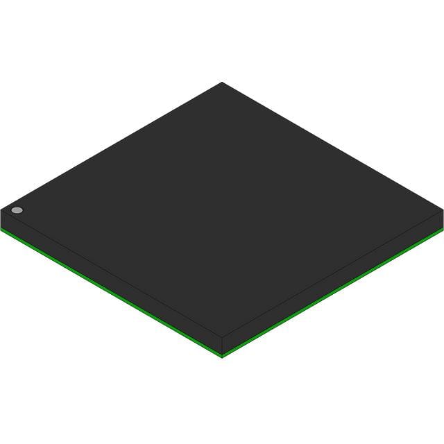
- Part No.:
- MCF5475ZP266
- Manufacturer:
- NXP Semiconductors
- Category:
- Microcontrollers
- Package:
- 388-BBGA
- Datasheet:
-
 MCF5475ZP266.pdf
- Description:
- IC MCU 32BIT ROMLESS 388PBGA
- Quantity:
- Payment:

- Shipping:

Inventory:1,231
Please send an inquiry. Send us your inquiry, and we will respond immediately.
Product details
Overview
MCF5475ZP266 from Freescale Semiconductor is a ColdFire V4e-based 32-bit microprocessor with integrated DDR SDRAM controller, PCI 2.2 interface, dual 10/100 Mbps Ethernet controllers, USB 2.0 device controller, and optional cryptography accelerator. It operates at up to 266 MHz core frequency (410 MIPS), features 32-Kbyte instruction and data caches, MMU, FPU compliant with IEEE-754 double-precision, and supports industrial networking and embedded control applications.
For engineers reviewing the MCF5475ZP266 datasheet, MCF5475ZP266 pinout, MCF5475ZP266 application, or MCF5475ZP266 equivalent, key selection considerations include its TEPBGA–388 package, 1.5V core / 2.5V DDR / 3.3V I/O voltage domains, 266 MHz peak performance, integrated FlexBus for glueless peripheral interfacing, and support for real-time deterministic communication stacks in telecom infrastructure and industrial gateways.
Technical Context
The MCF5475ZP266 implements a limited superscalar ColdFire V4e core with Harvard architecture, separate 32-Kbyte instruction and data caches, and a Memory Management Unit enabling full Linux OS support. Its internal XLB bus arbiter manages concurrent access from multiple masters including CPU, DMA, FECs, and USB.
It integrates a 32-bit DDR SDRAM controller supporting 66–133 MHz operation and up to 1 GB external memory across four chip selects, alongside a PCI 2.2 controller operating at 33–66 MHz with support for five external PCI masters and configurable bus-to-XLB divider ratios (1:1, 1:2, 1:4).
Key Specifications
| Parameter | Value and Actual Design Meaning |
|---|---|
| Core Architecture | ColdFire V4e - limited superscalar, Harvard, with MMU and IEEE-754 double-precision FPU |
| Max Core Frequency | 266 MHz - delivers 410 MIPS (Dhrystone 2.1), enabling real-time Linux and protocol stacks |
| Memory Interface | 32-bit DDR/SDR SDRAM controller - supports 66–133 MHz operation, built-in refresh, up to 1 GB addressable space |
| PCI Interface | PCI 2.2 compliant - 32-bit initiator/target, 33–66 MHz, supports up to five external PCI masters |
| Communications Peripherals | Dual 10/100 Mbps FECs with 2-Kbyte FIFOs each; USB 2.0 device controller with 4-Kbyte endpoint FIFO RAM and integrated PHY |
| Package & Thermal | TEPBGA–388, 27 mm × 27 mm - junction-to-ambient thermal resistance θJMA = 19°C/W (4-layer board) |
| Power Supply Domains | 1.5V (IVDD/PLL VDD), 2.5V (SD VDD for DDR), 3.3V (EVDD for PCI/FlexBus/I/O) - requires strict sequencing per Figure 3 |
Pinout & Package
Package: TEPBGA–388 (27 mm × 27 mm), ball pitch 1.0 mm, RoHS-compliant. Pinout conforms to Freescale Document Number MCF5475EC Rev. 4, with dedicated banks for DDR SDRAM (SDDATA[31:0], SDADDR[12:0], SDCLK[1:0], SDDQS[3:0]), PCI (PCIAD[31:0], PCICXBE[3:0], PCIFRM), FlexBus (AD[31:0], FBCS[5:0], R/W), and high-speed serial interfaces (USBD+, USBD−, PSCnTXD/RTS, DSPI signals).
| Pin/Terminal | Circuit Role | Design Meaning |
|---|---|---|
| SDCLK0/SDCLK1 | DDR SDRAM clock output | Differential clock pair driving DDR memory; requires matched trace length and 90-Ω differential impedance |
| SDDQS0–SDDQS3 | DDR DQS strobe outputs | Source-synchronous strobes for SDDATA[31:0]; critical for DDR timing closure and write leveling |
| PCIAD[31:0] | PCI address/data multiplexed bus | 32-bit multiplexed address/data lines; supports burst transfers and PCI target/initiator modes |
| FBCS0–FBCS5 | FlexBus chip select outputs | Independent enables for boot ROM, flash, SRAM, or peripherals; FBCS0 programmable for byte/word/longword access |
| USBD+, USBD− | USB 2.0 differential data pair | Full-speed/high-speed signaling; requires 90-Ω differential impedance, <200-mil stubs, and continuous ground plane |
| RSTI | Asynchronous reset input | Active-low synchronous reset; minimum pulse width = 5 CLKIN cycles (e.g., 75 ns @ 66 MHz) |
Key Features
| Feature | Design Value |
|---|---|
| Floating Point Unit (FPU) | IEEE-754 double-precision compliant with eight registers - enables real-time signal processing and floating-point math without software emulation |
| Integrated Cryptography Accelerator | Hardware execution of DES/3DES, AES, RC4, MD5/SHA-1/SHA-256/HMAC, and RNG - offloads crypto operations from CPU, reducing latency in secure communications |
| Intelligent Multi-Channel DMA | 16-channel controller with scatter-gather support - enables zero-CPU-overhead data movement between FECs, USB, PSCs, and memory |
| System Integration Unit (SIU) | Interrupt controller, watchdog timer, two 32-bit slice timers, four 32-bit GP timers with PWM - provides deterministic real-time event handling and motor control capability |
| Debug & Test Infrastructure | ColdFire BDM port + IEEE 1149.1 JTAG TAP - enables full boundary scan, background debug, and real-time trace without halting CPU execution |
Applications
| Industrial Ethernet Gateway | Secure Telecom Edge Node |
|---|---|
Use Scenario: Aggregating Modbus TCP, EtherNet/IP, and PROFINET traffic across heterogeneous fieldbuses in factory automation. IC Role / Device Role / Timing Role: Primary application processor running real-time Linux, managing dual FECs for redundant LAN ports and FlexBus-connected protocol co-processors. Use Value: Integrated MMU and 266 MHz performance enable concurrent protocol stack execution; DDR controller supports large buffer pools for packet queuing and deep inspection. |
Use Scenario: Deploying encrypted VoIP, SIP trunking, and firewall services in carrier-grade small cell backhaul units. IC Role / Device Role / Timing Role: Host processor executing Linux-based security middleware, leveraging hardware crypto accelerator for TLS 1.2/1.3 handshake acceleration and AES-GCM encryption. Use Value: Dedicated crypto engine reduces CPU load by >70% during SSL/TLS sessions; USB 2.0 interface enables secure firmware update via trusted dongle. |
| Medical Imaging Control Unit | Automotive Diagnostic Master |
Use Scenario: Real-time image acquisition and preprocessing from ultrasound transducers before transmission to PACS servers. IC Role / Device Role / Timing Role: Deterministic data hub coordinating high-throughput PSC-based sensor interfaces, DSPI-configured ADCs, and FEC-driven Gigabit Ethernet output. Use Value: 32-Kbyte caches and FPU accelerate FFT and filtering algorithms; FlexBus enables direct connection to FPGA-based beamforming logic without glue logic. |
Use Scenario: UDS (ISO 14229) and DoIP (ISO 13400) diagnostic gateway bridging CAN FD vehicle networks to Wi-Fi/Ethernet cloud services. IC Role / Device Role / Timing Role: Central protocol translator with dual FECs for vehicle-side and cloud-side links, PSCs for CAN FD transceivers, and SIU timers for precise diagnostic response timing. Use Value: Hardware timer PWM and compare functions ensure sub-millisecond UDS service response compliance; PCI interface allows optional expansion with PCIe-to-CAN FD bridge cards. |
Equivalent & Alternatives
The following parts are listed as comparable options for similar microprocessor applications.
| Alternative Part | Technical Difference | Application Difference | Selection Advice |
|---|---|---|---|
| MPC8313EVRAGDB | PowerPC e300 core @ 400 MHz; lacks integrated DDR controller (requires external memory controller); includes SATA and PCIe | Better suited for storage-centric edge nodes; no native USB 2.0 device mode or crypto accelerator | Select when PCIe expansion or SATA host capability is required over USB device functionality and hardware crypto |
| i.MX27ADS | ARM926EJ-S core @ 400 MHz; integrated LCD controller and CMOS sensor interface; no PCI or DDR SDRAM controller | Optimized for multimedia HMI and camera-based systems; lacks industrial I/O interfaces like FlexBus and FECs | Select for human-machine interface or vision applications where display/camera integration outweighs networking and real-time deterministic I/O needs |
Compared with MPC8313EVRAGDB and i.MX27ADS, the MCF5475ZP266 uniquely combines ColdFire V4e deterministic execution, integrated DDR/PCI/FlexBus, dual FECs, and hardware crypto - making it optimal for industrial protocol gateways requiring Linux, real-time I/O, and secure communications without external bridge chips.
Availability
MCF5475ZP266 is available at Aetrix Electronics and suitable for industrial networking gateways, telecom edge nodes, medical imaging subsystems, and automotive diagnostic master units requiring stable component supply and long-term lifecycle support.
Supply support for MCF5475ZP266 includes scheduled delivery planning, volume procurement assistance, BOM continuity management, traceable sourcing, and lifecycle availability coordination for OEM customers, industrial embedded developers, connected-device designers, and electronics production programs.
Manufacturer
Freescale Semiconductor (now part of NXP Semiconductors) is a fabless semiconductor company specializing in embedded processors, analog, and connectivity solutions for automotive, industrial, and networking markets.
The MCF5475ZP266 belongs to the ColdFire MCF547x family, designed specifically for high-performance, feature-rich embedded control applications requiring Linux-capable processing, deterministic real-time I/O, and integrated high-speed interconnects - targeting industrial automation, telecom infrastructure, and secure edge devices.
FAQ
What is the maximum operating junction temperature for the MCF5475ZP266?
The MCF5475ZP266 has a maximum operating junction temperature (Tj) of 105°C, as specified in Table 2 of the MCF5475EC Rev. 4 datasheet. This limit must be maintained under all operating conditions using appropriate thermal design - including PCB layout with thermal vias, copper pour, and heatsinking - especially given its estimated power consumption of less than 1.5W in the 388-pin PBGA package.
Does the MCF5475ZP266 support both DDR and SDR SDRAM simultaneously?
No, the MCF5475ZP266 DDR SDRAM controller supports either DDR or SDR SDRAM operation, but not both simultaneously. The mode is configured at boot time via configuration registers and hardware strapping options. Section 9 of the MCF5475EC Rev. 4 datasheet confirms the controller is mutually exclusive in DDR vs. SDR mode, with distinct AC timing specifications provided for each in Tables 11 and 13.
What voltage sequencing is required for reliable power-up of the MCF5475ZP266?
The MCF5475ZP266 requires strict voltage sequencing: IVDD/PLL VDD and EVDD/SD VDD must track up to 0.9V, then separate to reach final voltages (1.5V, 2.5V, 3.3V). IVDD must never exceed EVDD or SD VDD by more than 0.4V during ramp-up. Rise times must be slower than 1 µs to prevent ESD diode conduction. This is detailed in Section 4.2.1 of the MCF5475EC Rev. 4 datasheet.
Can the MCF5475ZP266 operate as a USB 2.0 host?
No, the MCF5475ZP266 implements only a USB 2.0 device controller - not a host controller. Its USB interface supports control, interrupt, bulk, and isochronous transfers in device mode only, with one control and six programmable endpoints. There is no OHCI/EHCI hardware, UTMI+ interface, or root hub functionality. This is explicitly stated in the "Communications I/O subsystem" section of the MCF5475EC Rev. 4 datasheet.
Is the cryptography accelerator module optional or integrated in the MCF5475ZP266?
The cryptography accelerator is an integrated, silicon-hardened module within the MCF5475ZP266 die - not an external option or software library. It provides dedicated execution units for DES/3DES, AES, RC4, MD5/SHA-1/SHA-256/HMAC, and RNG, accessible via memory-mapped registers. Its presence is confirmed in the "Features list" and block diagram (Figure 1) of the MCF5475EC Rev. 4 datasheet.
MCF5475ZP266 Specifications
- Product attributes
- Attribute value
- Manufacturer:
- NXP Semiconductors
- Package/Case:
- 388-BBGA
- Series:
- MCF547x
- Packaging:
- Tray
- Product Status:
- Not For New Designs
- Programmable:
- Not Verified
- Core Processor:
- Coldfire V4E
- Core Size:
- 32-Bit Single-Core
- Speed:
- 266MHz
- Connectivity:
- EBI/EMI, Ethernet, I2C, SPI, UART/USART, USB
- Peripherals:
- DMA, PWM, WDT
- Number of I/O:
- 99
- Program Memory Size:
- -
- Program Memory Type:
- ROMless
- EEPROM Size:
- -
- RAM Size:
- 32K x 8
- Voltage - Supply (Vcc/Vdd):
- 1.43V ~ 1.58V
- Data Converters:
- -
- Oscillator Type:
- External
- Operating Temperature:
- 0°C ~ 70°C (TA)
- Grade:
- -
- Qualification:
- -
- Mounting Type:
- Surface Mount
- Supplier Device Package:
MCF5475ZP266 FAQ
1.How can I place an order for MCF5475ZP266 through Aetrix?
Please submit a Request for Quotation (RFQ) for MCF5475ZP266 on Aetrix. Our sales agent will provide a competitive quotation and guide you through the order confirmation once you accept the terms.
2.Are the price and stock information for MCF5475ZP266 reliable?
The price and inventory of MCF5475ZP266 are updated periodically and may fluctuate due to market conditions. Stock and pricing data are typically refreshed every 24 hours. Quotation validity for MCF5475ZP266 is usually 5 days.
3.What payment methods are accepted for MCF5475ZP266?
We accept Wire Transfer, PayPal, Credit Card, Western Union, MoneyGram, and Escrow for MCF5475ZP266 transactions.
Note: Certain payment methods may incur a processing fee.
4.How is shipping managed for MCF5475ZP266?
MCF5475ZP266 orders can be shipped via leading logistics carriers, including DHL, UPS, FedEx, TNT, or Registered Mail.
Once your MCF5475ZP266 order is processed, you will receive an email with the shipment details and tracking number.
Note: Tracking information may take up to 24 hours to appear. Express delivery typically takes 3–5 business days.
5.How can I obtain technical support or documentation for MCF5475ZP266?
For technical support, including MCF5475ZP266 datasheets, pinout diagrams, or application guidance, please contact our engineering support team. They can provide detailed documentation and assistance for your MCF5475ZP266 requirements.
6.How does Aetrix verify that MCF5475ZP266 is sourced from the original manufacturer or authorized distributors?
All MCF5475ZP266 products on Aetrix are procured from qualified distributors and authorized channels. Our dedicated quality assurance team conducts strict verification, including traceability checks and, if necessary, third-party testing. This ensures that MCF5475ZP266 meets industry standards.
7.What is the process for return or replacement of MCF5475ZP266?
All MCF5475ZP266 units undergo pre-shipment inspection (PSI). If there is an issue with MCF5475ZP266, returns or replacements are accepted under the following conditions:
1.Quantity discrepancies, incorrect items, or visible external defects (such as breakage or corrosion), acknowledged by Aetrix.
2.The issue is reported within 90 days of delivery.
3.The MCF5475ZP266 part is unused and in its original packaging.
Return procedure for MCF5475ZP266:
1.Submit a request within 90 days.
2.Obtain a Return Material Authorization (RMA) from Aetrix.
MCF5475ZP266 Tags

-
ATTINY4-TSHR
Microchip Technology
-
ATTINY10-TSHR
Microchip Technology
-
ATTINY10-TS8R
Microchip Technology

-
ATTINY202-SSNR
Microchip Technology
-
ATTINY202-SSFR
Microchip Technology
-
ATTINY402-SSNR
Microchip Technology

-
PIC16F15213T-I/MF
Microchip Technology
-
PIC16F15213-E/MF
Microchip Technology

-
PIC10F200T-I/OT
Microchip Technology
-
ATTINY412-SSNR
Microchip Technology
-
PIC10F202T-I/OT
Microchip Technology

-
ATTINY404-SSNR
Microchip Technology
Tech Hub

A practical engineering guide to 3.3V and 5V logic compatibility, input thresholds, resistor dividers, translator ICs, MOSFET level shifting, I2C pull-ups, timing limits and power-sequencing risks.

The 74HC595 uses push-pull logic outputs, while the TPIC6B595 uses 50 V open-drain DMOS sinks for higher-power loads. This guide compares timing, current limits, 3.3 V interfacing, load wiring, thermal…

The 74HC595 converts serial data into eight stable parallel outputs. This guide covers pin functions, shift and storage timing, OE and MR behavior, drive-current limits, cascading, voltage compatibilit…

A technical comparison of level-sensitive latches and edge-triggered flip-flops, covering timing windows, setup and hold limits, master–slave operation, time borrowing, race-through, HDL inference and…

A D latch stores one bit while Enable controls when data can pass. This reference covers gate-level operation, truth tables, transparency, setup and hold timing, LE versus OE, common ICs and practical …

An SR latch stores one bit through cross-coupled feedback. This engineering reference covers NOR and NAND implementations, truth tables, forbidden-state recovery, gated operation, switch debouncing, fa…

Latch circuits retain one bit through feedback. This technical reference covers SR and D latches, truth tables, transparency, timing limits, latch-versus-flip-flop behavior, applications and common log…

An engineering guide to LED driver operation, constant-current and constant-voltage outputs, linear and switching topologies, dimming, IC selection, calculations, replacement compatibility, and fault c…

Operational amplifier guide covering op amp basics, feedback, ideal vs real op amps, common configurations, buffer circuits, offset, bias current, gain-bandwidth, slew rate, rail-to-rail limits and sel…

Jumper cables guide covering safe connection order, red and black clamp placement, final ground connection, cable gauge, length, clamp quality, copper vs CCA cables, jump starter comparison and battery…


