
 My Inquiry
 My Account


NXP Semiconductors MCIMX351AJQ5C
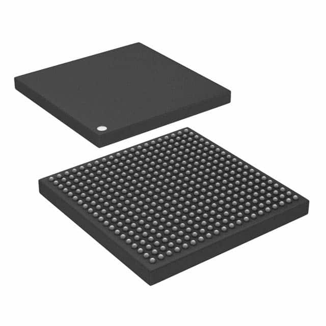
- Part No.:
- MCIMX351AJQ5C
- Manufacturer:
- NXP Semiconductors
- Category:
- Microprocessors
- Package:
- 400-LFBGA
- Datasheet:
-
 MCIMX351AJQ5C.pdf
- Description:
- IC MPU I.MX35 532MHZ 400LFBGA
- Quantity:
- Payment:

- Shipping:

Inventory:1,611
Please send an inquiry. Send us your inquiry, and we will respond immediately.
Product details
Overview
MCIMX351AJQ5C from NXP Semiconductors (formerly Freescale) is an AEC-Q100 Grade 3 qualified automotive application processor based on the ARM1136JF-S core operating at 532 MHz, featuring 16 KB L1 instruction cache, 16 KB L1 data cache, 128 KB L2 cache, and integrated image processing unit (IPU) for real-time video preprocessing and display control in infotainment head units.
For engineers reviewing the MCIMX351AJQ5C datasheet, MCIMX351AJQ5C pinout, MCIMX351AJQ5C application, or MCIMX351AJQ5C equivalent, key selection considerations include its 532 MHz CPU frequency, -40°C to +85°C ambient rating, MAPBGA-5284 (17 × 17 mm, 0.8 mm pitch) package, dual CAN interfaces, USB 2.0 OTG with internal HS PHY, and absence of OpenVG GPU and PATA support per i.MX35 family documentation.
Technical Context
The MCIMX351AJQ5C implements the ARM1136JF-S core (r1p3) with Jazelle Java acceleration, VFP11 co-processor, and eight-stage pipeline with branch prediction. Its AP domain integrates a 128 KB L2 cache, MMU, and IPUv1 for camera sensor interface (up to 30 Mpixels/s), color space conversion, and display controller functions.
Power management leverages clock gating, power gating, and well biasing to reduce leakage-enabling operation at 1.22 V core voltage. The shared domain includes SDMA engine, EMI supporting mobile DDR/DDR2/SDRAM, and peripheral interconnect via SPBA and AIPS buses, with silicon revision 2.1 requiring distinct ball map (Table 95/Table 97) incompatible with revision 2.0 layouts.
Key Specifications
| Parameter | Value and Actual Design Meaning |
|---|---|
| CPU Core | ARM1136JF-S (r1p3), 532 MHz max - enables real-time multimedia execution with Jazelle and SIMD DSP extensions |
| Memory Cache | 16 KB L1 instruction + 16 KB L1 data + 128 KB L2 cache - reduces external memory bandwidth demand and latency |
| Operating Temp | -40°C to +85°C ambient - meets AEC-Q100 Grade 3 requirements for under-dash automotive environments |
| Package | MAPBGA-5284, 17 × 17 mm, 0.8 mm pitch, RoHS-compliant, MSL 3 - supports high-density automotive PCB layouts |
| Integrated IPU | Image Processing Unit v1 - offloads ARM core for camera input (YUV/YCC, 4/8/10/16-bit), rotation, scaling, and display blending |
| Connectivity | Dual FlexCAN 2.0B, USB 2.0 OTG (480 Mbps w/ internal HS PHY), 3x UART (4.0 Mbps), 2x CSPI (52 Mbps), ESAI, SPDIF - targets infotainment bus integration |
| Memory Support | Mobile DDR, DDR2 (4-bank), SDRAM (133 MHz), SLC/MLC NAND, NOR Flash - enables flexible boot and storage architecture |
Pinout & Package
MCIMX351AJQ5C uses a 5284-case MAPBGA package (17 × 17 mm, 0.8 mm pitch, 361 balls), RoHS-compliant and moisture-sensitive level 3. Ball map follows silicon revision 2.1 layout (Table 95/Table 97), incompatible with revision 2.0 designs.
| Pin/Terminal | Circuit Role | Design Meaning |
|---|---|---|
| EXT_ARMCLK | External ARM Clock Input | Optional clock source for ARM core; used when internal PLLs are disabled or during debug synchronization |
| USBOH_DP / USBOH_DM | USB 2.0 OTG High-Speed Differential Pair | Direct connection to internal HS PHY; requires 90 Ω differential impedance routing and ESD protection |
| FLEXCAN1_TX / FLEXCAN1_RX | CAN 2.0B Bus Interface | Supports 1 Mbps automotive network communication; requires external transceiver and termination resistors |
| ESAI_TXFS / ESAI_TXCK | Enhanced Serial Audio Interface Frame Sync & Clock | Configurable master/slave audio timing signals for codec interfacing; supports TDM and I2S protocols |
| GPIO1_0 | Power Ready Signal Input | Used as PMIC power-ready assertion line; triggers system initialization upon stable VDD rail detection |
Key Features
| Feature | Design Value |
|---|---|
| AEC-Q100 Grade 3 Qualification | Validated for automotive under-hood and cabin environments with guaranteed operation from -40°C to +85°C ambient |
| Integrated Image Processing Unit (IPUv1) | Enables real-time camera sensor interface (30 Mpixels/s), YUV/YCC conversion, rotation, scaling, and overlay without CPU load |
| Dual FlexCAN 2.0B Controllers | Supports redundant or multi-bus automotive networking (e.g., instrument cluster + infotainment CAN domains) |
| USB 2.0 OTG with Internal HS PHY | Eliminates need for external ULPI PHY; enables direct connection to USB peripherals or host devices at 480 Mbps |
| 128 KB On-Chip SRAM | Provides low-latency scratchpad memory for real-time OS tasks, audio buffers, or secure boot code execution |
| Advanced Power Management | Combines clock/power gating and well biasing to reduce subthreshold leakage by ~10× versus nominal process |
Applications
| Automotive Infotainment Head Unit | In-Vehicle Navigation System |
|---|---|
|
Use Scenario: Central multimedia hub integrating touchscreen UI, Bluetooth hands-free, audio playback, and rear-view camera display. IC Role / Device Role / Timing Role: Primary application processor executing Linux/QNX OS, managing display rendering via IPU, and coordinating CAN/USB/UART peripherals. Use Value: 532 MHz ARM11 core and dedicated IPU enable concurrent video decode (QVGA), graphics overlay, and telematics processing without frame drops. |
Use Scenario: Real-time GPS navigation with map rendering, route calculation, voice guidance, and traffic data over cellular modem. IC Role / Device Role / Timing Role: Host processor running navigation stack, interfacing to GPS receiver via UART, and driving WVGA display through parallel interface. Use Value: Dual CAN interfaces allow simultaneous communication with vehicle speed sensor (CAN1) and instrument cluster (CAN2) for context-aware UI updates. |
| Driver Information Display (DID) | Automotive Rear-Seat Entertainment |
|
Use Scenario: Digital instrument cluster displaying speed, RPM, warnings, and ADAS alerts using high-reliability graphics. IC Role / Device Role / Timing Role: Graphics-capable SoC rendering vector-based gauges and animations via parallel display interface and IPU-accelerated compositing. Use Value: 128 KB on-chip SRAM ensures deterministic response for safety-critical overlays; AEC-Q100 Grade 3 guarantees long-term reliability. |
Use Scenario: Dual-screen entertainment system with HDMI output, wireless headphones, and media streaming from USB/SD card. IC Role / Device Role / Timing Role: Media processor handling compressed audio/video decode, USB mass storage access, and SPDIF audio output. Use Value: ESAI and SPDIF transceiver support enable low-jitter digital audio output to premium car audio amplifiers without external codecs. |
Equivalent & Alternatives
The following parts are listed as comparable options for similar automotive application processor applications.
| Alternative Part | Technical Difference | Application Difference | Selection Advice |
|---|---|---|---|
| MCIMX355AJQ5C | Includes PATA and CE-ATA interfaces; otherwise identical CPU, cache, IPU, and peripheral set | Required for systems needing IDE hard drive or embedded ATA storage connectivity | Select MCIMX355AJQ5C only if PATA/CE-ATA is mandatory; MCIMX351AJQ5C reduces BOM cost and layout complexity where not needed |
| MCIMX356AJQ5C | Adds OpenVG 1.1 GPU and enhanced graphics acceleration; retains same CPU, IPU, and automotive qualification | Suitable for advanced GUIs with vector graphics, smooth animations, and OpenGL ES 1.1 compatibility | Choose MCIMX356AJQ5C when OpenVG GPU acceleration is required; MCIMX351AJQ5C suffices for bitmap-based UIs and video-centric use cases |
Compared with MCIMX355AJQ5C and MCIMX356AJQ5C, the MCIMX351AJQ5C provides optimal cost-performance balance for video-enabled infotainment without PATA or GPU overhead-reducing PCB layer count, thermal design margin, and software driver complexity while retaining full AEC-Q100 Grade 3 compliance and IPU-based camera/display functionality.
Availability
MCIMX351AJQ5C is available at Aetrix Electronics and suitable for automotive infotainment head units, in-vehicle navigation systems, and driver information displays requiring stable component supply across extended production lifecycles.
Supply support for MCIMX351AJQ5C includes scheduled delivery planning, volume procurement assistance, BOM continuity management, traceable sourcing, and lifecycle availability coordination for OEM customers, industrial embedded developers, connected-device designers, and electronics production programs.
Manufacturer
NXP Semiconductors is a global semiconductor leader focused on secure connectivity solutions for automotive, industrial, and IoT applications, with deep expertise in automotive-grade SoCs and functional safety.
The i.MX35 product line was designed specifically for AEC-Q100-compliant automotive infotainment and navigation systems, emphasizing low-power multimedia processing, robust peripheral integration (CAN, USB, ESAI), and long-term supply assurance.
FAQ
What is the maximum operating frequency of the MCIMX351AJQ5C?
The MCIMX351AJQ5C operates at a maximum frequency of 532 MHz, as confirmed in Table 1 of the MCIMX35SR2AEC datasheet (Rev. 10). This speed rating applies to silicon revision 2.1 and meets all specifications of the 400 MHz variant, allowing drop-in replacement in existing 400 MHz designs without derating.
Does the MCIMX351AJQ5C include an OpenVG-compatible graphics processing unit?
No, the MCIMX351AJQ5C does not include an OpenVG 1.1 GPU. As explicitly stated in Section 1.1 and Table 2 of the datasheet, OpenVG graphics acceleration is unavailable for the MCIMX351 variant-only MCIMX353, MCIMX355, MCIMX356, and MCIMX357 support this feature.
Is the MCIMX351AJQ5C qualified for automotive use?
Yes, the MCIMX351AJQ5C is AEC-Q100 Grade 3 qualified and rated for ambient operating temperatures from -40°C to +85°C, making it suitable for automotive infotainment and navigation applications installed in passenger compartments.
What package type and ball count does the MCIMX351AJQ5C use?
The MCIMX351AJQ5C uses a MAPBGA package designated Case 5284, measuring 17 × 17 mm with 0.8 mm pitch and 361 signal balls. Its silicon revision 2.1 ball map (Table 95/Table 97) is incompatible with revision 2.0 layouts, requiring strict adherence to the correct footprint.
Which external memory types are supported by the MCIMX351AJQ5C?
The MCIMX351AJQ5C supports mobile DDR, DDR2 (4-bank architecture), SDRAM (up to 133 MHz), SLC/MLC NAND Flash, NOR Flash, and SRAM via its External Memory Interface (EMI), as detailed in Section 1 and Table 4 of the MCIMX35SR2AEC datasheet.
MCIMX351AJQ5C Specifications
- Product attributes
- Attribute value
- Manufacturer:
- NXP Semiconductors
- Package/Case:
- 400-LFBGA
- Series:
- i.MX35
- Packaging:
- Tray
- Product Status:
- Active
- Core Processor:
- ARM1136JF-S
- Number of Cores/Bus Width:
- 1 Core, 32-Bit
- Speed:
- 532MHz
- Co-Processors/DSP:
- Multimedia; VFP
- RAM Controllers:
- LPDDR, DDR2
- Graphics Acceleration:
- No
- Display & Interface Controllers:
- Keypad, KPP, LCD
- Ethernet:
- 10/100Mbps (1)
- SATA:
- -
- USB:
- USB 2.0 + PHY (2)
- Voltage - I/O:
- 1.8V, 2.0V, 2.5V, 2.7V, 3.0V, 3.3V
- Operating Temperature:
- -40°C ~ 85°C (TA)
- Grade:
- -
- Qualification:
- -
- Security Features:
- Secure Fusebox, Secure JTAG
- Mounting Type:
- Surface Mount
- Supplier Device Package:
- 400-LFBGA (17x17)
- Additional Interfaces:
- 1-Wire, ASRC, ATA, CAN, I2C, I2S, MMC/SDIO, SAI, SDHC, SPI, SSI, UART
MCIMX351AJQ5C FAQ
1.How can I place an order for MCIMX351AJQ5C through Aetrix?
Please submit a Request for Quotation (RFQ) for MCIMX351AJQ5C on Aetrix. Our sales agent will provide a competitive quotation and guide you through the order confirmation once you accept the terms.
2.Are the price and stock information for MCIMX351AJQ5C reliable?
The price and inventory of MCIMX351AJQ5C are updated periodically and may fluctuate due to market conditions. Stock and pricing data are typically refreshed every 24 hours. Quotation validity for MCIMX351AJQ5C is usually 5 days.
3.What payment methods are accepted for MCIMX351AJQ5C?
We accept Wire Transfer, PayPal, Credit Card, Western Union, MoneyGram, and Escrow for MCIMX351AJQ5C transactions.
Note: Certain payment methods may incur a processing fee.
4.How is shipping managed for MCIMX351AJQ5C?
MCIMX351AJQ5C orders can be shipped via leading logistics carriers, including DHL, UPS, FedEx, TNT, or Registered Mail.
Once your MCIMX351AJQ5C order is processed, you will receive an email with the shipment details and tracking number.
Note: Tracking information may take up to 24 hours to appear. Express delivery typically takes 3–5 business days.
5.How can I obtain technical support or documentation for MCIMX351AJQ5C?
For technical support, including MCIMX351AJQ5C datasheets, pinout diagrams, or application guidance, please contact our engineering support team. They can provide detailed documentation and assistance for your MCIMX351AJQ5C requirements.
6.How does Aetrix verify that MCIMX351AJQ5C is sourced from the original manufacturer or authorized distributors?
All MCIMX351AJQ5C products on Aetrix are procured from qualified distributors and authorized channels. Our dedicated quality assurance team conducts strict verification, including traceability checks and, if necessary, third-party testing. This ensures that MCIMX351AJQ5C meets industry standards.
7.What is the process for return or replacement of MCIMX351AJQ5C?
All MCIMX351AJQ5C units undergo pre-shipment inspection (PSI). If there is an issue with MCIMX351AJQ5C, returns or replacements are accepted under the following conditions:
1.Quantity discrepancies, incorrect items, or visible external defects (such as breakage or corrosion), acknowledged by Aetrix.
2.The issue is reported within 90 days of delivery.
3.The MCIMX351AJQ5C part is unused and in its original packaging.
Return procedure for MCIMX351AJQ5C:
1.Submit a request within 90 days.
2.Obtain a Return Material Authorization (RMA) from Aetrix.
MCIMX351AJQ5C Tags

-
AT91SAM9260B-CU-999
Microchip Technology
-
AT91SAM9G25-CU
Microchip Technology

-
ATSAMA5D27C-CU
Microchip Technology
-
AT91SAM9X35-CU
Microchip Technology
-
AT91SAM9X25-CU
Microchip Technology

-
MCIMX6Y2CVM08AB
NXP Semiconductors
.JPG)
-
AM3352BZCZ100
Texas Instruments
-
AT91SAM9260B-CU
Microchip Technology

-
AT91SAM9260B-QU
Microchip Technology

-
ATSAMA5D31A-CU
Microchip Technology
-
AT91SAM9G20B-CU-999
Microchip Technology
-
MCIMX6Y2CVM05AB
NXP Semiconductors
Tech Hub

A practical engineering guide to 3.3V and 5V logic compatibility, input thresholds, resistor dividers, translator ICs, MOSFET level shifting, I2C pull-ups, timing limits and power-sequencing risks.

The 74HC595 uses push-pull logic outputs, while the TPIC6B595 uses 50 V open-drain DMOS sinks for higher-power loads. This guide compares timing, current limits, 3.3 V interfacing, load wiring, thermal…

The 74HC595 converts serial data into eight stable parallel outputs. This guide covers pin functions, shift and storage timing, OE and MR behavior, drive-current limits, cascading, voltage compatibilit…

A technical comparison of level-sensitive latches and edge-triggered flip-flops, covering timing windows, setup and hold limits, master–slave operation, time borrowing, race-through, HDL inference and…

A D latch stores one bit while Enable controls when data can pass. This reference covers gate-level operation, truth tables, transparency, setup and hold timing, LE versus OE, common ICs and practical …

An SR latch stores one bit through cross-coupled feedback. This engineering reference covers NOR and NAND implementations, truth tables, forbidden-state recovery, gated operation, switch debouncing, fa…

Latch circuits retain one bit through feedback. This technical reference covers SR and D latches, truth tables, transparency, timing limits, latch-versus-flip-flop behavior, applications and common log…

An engineering guide to LED driver operation, constant-current and constant-voltage outputs, linear and switching topologies, dimming, IC selection, calculations, replacement compatibility, and fault c…

Operational amplifier guide covering op amp basics, feedback, ideal vs real op amps, common configurations, buffer circuits, offset, bias current, gain-bandwidth, slew rate, rail-to-rail limits and sel…

Jumper cables guide covering safe connection order, red and black clamp placement, final ground connection, cable gauge, length, clamp quality, copper vs CCA cables, jump starter comparison and battery…


