
 My Inquiry
 My Account


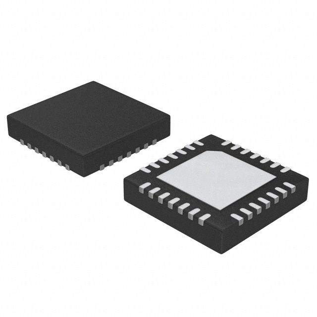
Microchip Technology MCP19117T-E/MQ
- Part No.:
- MCP19117T-E/MQ
- Manufacturer:
- Microchip Technology
- Category:
- DC DC Switching Controllers
- Package:
- 28-VFQFN Exposed Pad
- Datasheet:
-
 MCP19117T-E/MQ.pdf
- Description:
- IC PWM CTLR SYNC LOW SIDE 28QFN
- Quantity:
- Payment:

- Shipping:

Inventory:3,518
Please send an inquiry. Send us your inquiry, and we will respond immediately.
Product details
Overview
MCP19117T-E/MQ from Microchip Technology is a digitally enhanced, mixed-signal synchronous low-side PWM controller with integrated 8-bit microcontroller core, designed for LED lighting, battery charging, and isolated/non-isolated DC-DC converters. It supports flyback, boost, SEPIC, and Ćuk topologies; operates from 4.5V to 42V input; delivers dual low-side gate drive (1A/10V or 0.5A/5V); features peak current mode control, differential remote output sensing, and AEC-Q100 qualification.
For engineers reviewing the MCP19117T-E/MQ datasheet, MCP19117T-E/MQ pinout, MCP19117T-E/MQ application, or MCP19117T-E/MQ equivalent, key selection considerations include its 28-pin QFN package, programmable dead time (16–256 ns), fixed-frequency range (31.25 kHz–2 MHz), quasi-resonant capability with built-in comparator, and integrated 10-bit ADC with seven analog inputs.
Technical Context
The MCP19117T-E/MQ integrates an analog PWM controller (similar to MCP1631) with a PIC®-compatible 8-bit microcontroller core (8192-word Flash, 336-byte RAM). Its dual low-side gate drivers support independent dead-time programming and operate at either 5V (0.5A sink/source) or 10V (1A sink/source) VDR, enabled via external voltage doubler (e.g., TC1240A).
It implements peak current mode control with leading-edge blanking (0/50/100/200 ns), 6-bit slope compensation, and differential current sensing using integrated low-side amplifier. The device uses two internal LDOs: 5V VDD for digital core and 4V AVDD for analog circuitry, with selectable ADC reference (VDD or AVDD).
Key Specifications
| Parameter | Value and Actual Design Meaning |
|---|---|
| Input Voltage Range | +4.5V to +42V - Supports wide-input industrial and automotive power supplies; absolute max 44V continuous, 48V transient (500 ms). |
| Gate Drive Capability | 1A sink/source @ 10V VDR - Enables direct driving of medium-power MOSFETs without external buffers in high-efficiency converters. |
| Switching Frequency | 31.25 kHz to 2.0 MHz - Programmable fixed-frequency operation allows optimization for EMI, size, and efficiency across topologies. |
| ADC Resolution & Channels | 10-bit, 7 external channels (AN0–AN7) - Enables precise closed-loop monitoring of input voltage, output voltage, temperature, and current in multi-sensor systems. |
| Program Memory | 8192 words Flash - Sufficient for complex startup/shutdown profiles, protection logic, and communication stacks (I²C/AUSART). |
| Quiescent Current | 5 mA typical - Minimizes no-load power loss in always-on applications such as LED drivers and standby power supplies. |
| Sleep Current | 50 µA typical - Enables ultra-low-power modes for battery-backed or energy-harvesting systems. |
Pinout & Package
Package: 28-pin QFN (5 mm × 5 mm, 0.5 mm pitch), exposed thermal pad, RoHS-compliant, moisture sensitivity level 3.
| Pin/Terminal | Circuit Role | Design Meaning |
|---|---|---|
| VIN | Input supply voltage input | Primary power rail connection; powers internal LDOs and bias circuits; requires input filtering per design guidelines. |
| VDD | +5V LDO output | Supplies microcontroller core and digital peripherals; can source gate drive when used with external RC filter to VDR. |
| VDR | Gate drive supply voltage | Accepts 4.5V–12V; determines gate drive strength (1A @ 10V, 0.5A @ 5V); must be decoupled with dual 4.7 µF caps and 10Ω isolation resistor. |
| PDRV / SDRV | Primary / secondary low-side gate drive outputs | CMOS push-pull outputs with independent programmable dead time (16–256 ns); support bidirectional converter operation. |
| ISP / ISN | Current sense amplifier non-inverting / inverting inputs | Differential inputs for secondary-side current sensing; integrated amplifier enables accurate low-side current measurement. |
| VS / IFB / ICOMP | Output voltage sense / error amp feedback / error amp output | Forms closed-loop voltage regulation path; VS connects to resistive divider; IFB accepts feedback signal; ICOMP drives external compensation network. |
| DESATP/ISOUT / DESATN | DESAT comparator positive input or current sense output / DESAT comparator negative input | Configurable pin: enables quasi-resonant zero-voltage switching detection (DESAT mode) or secondary current monitor output (ISOUT mode). |
| GPA0–GPA3, GPB0–GPB7 | General-purpose I/O with analog/digital functions | Eight configurable GPIOs (including open-drain options); support ADC (AN0–AN7), UART (RX/DT, TX/CK), I²C (SDA/SCL), ICSP (ICSPDAT/ICSPCLK), and capture/compare (CCD). |
Key Features
| Feature | Design Value |
|---|---|
| Integrated 10-bit ADC with 7 channels | Enables simultaneous monitoring of input voltage, output voltage, temperature, and up to four current paths without external sensors. |
| Programmable leading-edge blanking (LEB) | Four selectable values (0/50/100/200 ns) prevent false overcurrent triggering during MOSFET turn-on transients. |
| Dual low-side gate drivers with independent dead-time control | Eliminates shoot-through risk in synchronous rectification or bidirectional topologies; supports phase-shifted or interleaved designs. |
| AEC-Q100 Grade 1 qualification | Validated for automotive ambient temperatures (−40°C to +125°C), enabling use in under-hood LED lighting and 12V/24V battery chargers. |
| Configurable UVLO/OVLO thresholds | Prevents unsafe operation during brown-out or overvoltage events; thresholds set digitally via registers, not fixed resistors. |
| I²C and AUSART communication interfaces | Allows real-time telemetry, firmware updates, and system-level coordination (e.g., dimming commands, fault reporting) without additional MCU overhead. |
Applications
| Automotive LED Headlamp Driver | Industrial Battery Charger |
|---|---|
|
Use Scenario: High-brightness LED headlamps requiring constant-current regulation, thermal derating, and CAN-linked dimming commands. IC Role / Device Role / Timing Role: Primary PWM controller and system manager; executes closed-loop current control, reads temperature via ADC, and interprets I²C dimming commands. Use Value: Eliminates need for separate MCU and analog controller; AEC-Q100 qualification ensures reliability in harsh automotive environments. |
Use Scenario: 24V lead-acid or Li-ion battery charger with adaptive charge profiling, input surge protection, and status reporting. IC Role / Device Role / Timing Role: Dual-role controller: manages synchronous rectification in buck-boost stage and implements state-machine-based CC/CV charging algorithm. Use Value: Integrated 8k-word Flash stores full charging profile; programmable OVLO/UVLO protects against grid instability; 50 µA sleep current extends standby life. |
| Isolated Flyback SMPS for Medical Equipment | High-Efficiency SEPIC LED Driver |
|
Use Scenario: Compact, low-noise 12V/5W isolated flyback supply for patient-connected devices requiring reinforced insulation and low EMI. IC Role / Device Role / Timing Role: Quasi-resonant flyback controller with DESAT-based ZVS detection; regulates output via optocoupler feedback to IFB pin. Use Value: Built-in QR comparator and offset adjustment reduce external component count; differential remote sensing improves load regulation accuracy to ±1%. |
Use Scenario: Wide-input (9–36V) constant-current LED driver for outdoor signage, supporting 12–48V LED strings with analog/digital dimming. IC Role / Device Role / Timing Role: SEPIC topology controller with primary current mode control; uses GPA0 as analog dimming input and GPB6 as PWM dimming output. Use Value: Seven ADC channels monitor input voltage, string voltage, heatsink temperature, and current sense; eliminates need for external DAC or op-amps. |
Equivalent & Alternatives
The following parts are listed as comparable options for similar digitally enhanced PWM controller applications.
| Alternative Part | Technical Difference | Application Difference | Selection Advice |
|---|---|---|---|
| MCP19116T-E/MQ | 24-pin QFN, 4 analog inputs (AN0–AN3), no GPB4–GPB7, no RX/DT on GPB7 | Limited I/O and ADC channels; suitable for simpler single-output LED drivers or chargers with minimal telemetry. | Select when board space is constrained and full 7-channel ADC or dual UART/I²C is unnecessary. |
| UCC28950PW | Fixed-function phase-shifted full-bridge controller; no integrated MCU, no Flash, no ADC | Requires external MCU for telemetry or adaptive control; optimized for high-power telecom/server PSUs, not LED/battery apps. | Choose only for high-efficiency, high-power (>200W) isolated full-bridge designs where digital flexibility is secondary to analog precision. |
Compared with MCP19116T-E/MQ, the MCP19117T-E/MQ adds four ADC channels, dual UART capability, and expanded GPIO-enabling richer system monitoring and control without external components. Versus UCC28950PW, it trades fixed-function analog performance for software-defined adaptability, making it superior for cost-sensitive, feature-rich, medium-power applications.
Availability
MCP19117T-E/MQ is available at Aetrix Electronics and suitable for automotive LED lighting, industrial battery charging, isolated medical power supplies, and high-efficiency SEPIC LED drivers requiring stable component supply, long-term lifecycle assurance, and traceable sourcing.
Supply support for MCP19117T-E/MQ includes scheduled delivery planning, volume procurement assistance, BOM continuity management, traceable sourcing, and lifecycle availability coordination for OEM customers, industrial embedded developers, connected-device designers, and electronics production programs.
Manufacturer
Microchip Technology Inc. is a leading provider of microcontroller, mixed-signal, analog, and Flash-IP solutions, serving automotive, industrial, consumer, and communications markets with high-reliability silicon and development tools.
The MCP19117T-E/MQ belongs to Microchip's Digitally Enhanced Power Analog (DEPA) controller family, engineered to replace discrete analog controllers + MCUs in medium-power DC-DC applications-delivering higher integration, faster time-to-market, and field-upgradable control algorithms.
FAQ
What topology configurations does the MCP19117T-E/MQ support?
The MCP19117T-E/MQ supports flyback, boost, SEPIC, and Ćuk topologies out of the box, with peak current mode control and programmable slope compensation. Its dual low-side gate drivers and quasi-resonant comparator enable robust implementation of synchronous rectified and ZVS-capable variants. The MCP19117T-E/MQ datasheet confirms compatibility with all four topologies on pages 9–12, including schematic examples for each.
How does the MCP19117T-E/MQ achieve AEC-Q100 qualification?
The MCP19117T-E/MQ achieves AEC-Q100 Grade 1 qualification through rigorous stress testing across −40°C to +125°C ambient, including HTOL, ESD, latch-up, and package reliability validation. This certification applies specifically to the MCP19117T-E/MQ device variant and is documented in Microchip's official qualification report DS20005479D, page 1.
Can the MCP19117T-E/MQ operate without external programming after power-up?
Yes-the MCP19117T-E/MQ contains factory-programmed boot code and default register settings that enable immediate operation in basic PWM mode. However, full utilization of its digital features (e.g., ADC calibration, I²C communication, custom protection thresholds) requires user firmware loaded via ICSP™ using MPLAB X IDE. The MCP19117T-E/MQ will function as a fixed-frequency PWM controller even without custom firmware.
What is the maximum gate drive voltage supported by the MCP19117T-E/MQ?
The MCP19117T-E/MQ supports gate drive voltages up to 12V on the VDR pin, with rated performance at 10V (1A sink/source) and 5V (0.5A sink/source). Higher VDR voltages require external regulation; Microchip recommends using the TC1240A voltage doubler from VDD to generate 10V VDR. The MCP19117T-E/MQ electrical specifications confirm VDR absolute maximum is 13.2V (DS20005479D, page 22).
Does the MCP19117T-E/MQ support both master and slave operation in multi-controller systems?
Yes-the MCP19117T-E/MQ supports master/slave configuration via the MSC<1:0> bits in the MODECON register. In master mode, GPB1 outputs VREF2 for synchronization; in slave mode, CLKPIN (GPA1) accepts external sync signals. This enables interleaving or coordinated control across multiple MCP19117T-E/MQ devices, as detailed in Section 6.0 of the datasheet.
MCP19117T-E/MQ Specifications
- Product attributes
- Attribute value
- Manufacturer:
- Microchip Technology
- Series:
- -
- Package/Case:
- 28-VFQFN Exposed Pad
- Packaging:
- Tape & Reel (TR)
- Product Status:
- Active
- Output Type:
- Transistor Driver
- Function:
- Step-Up, Step-Up/Step-Down
- Output Configuration:
- Positive
- Topology:
- Boost, Cuk, Flyback, SEPIC
- Number of Outputs:
- 1
- Output Phases:
- 1
- Voltage - Supply (Vcc/Vdd):
- 4.5V ~ 42V
- Frequency - Switching:
- 31.25kHz ~ 2MHz
- Duty Cycle (Max):
- -
- Synchronous Rectifier:
- No
- Clock Sync:
- Yes
- Serial Interfaces:
- I2C
- Control Features:
- EN
- Operating Temperature:
- -40°C ~ 125°C (TJ)
- Grade:
- Automotive
- Qualification:
- AEC-Q100
- Mounting Type:
- Surface Mount
- Supplier Device Package:
- 28-QFN (5x5)
MCP19117T-E/MQ FAQ
1.How can I place an order for MCP19117T-E/MQ through Aetrix?
Please submit a Request for Quotation (RFQ) for MCP19117T-E/MQ on Aetrix. Our sales agent will provide a competitive quotation and guide you through the order confirmation once you accept the terms.
2.Are the price and stock information for MCP19117T-E/MQ reliable?
The price and inventory of MCP19117T-E/MQ are updated periodically and may fluctuate due to market conditions. Stock and pricing data are typically refreshed every 24 hours. Quotation validity for MCP19117T-E/MQ is usually 5 days.
3.What payment methods are accepted for MCP19117T-E/MQ?
We accept Wire Transfer, PayPal, Credit Card, Western Union, MoneyGram, and Escrow for MCP19117T-E/MQ transactions.
Note: Certain payment methods may incur a processing fee.
4.How is shipping managed for MCP19117T-E/MQ?
MCP19117T-E/MQ orders can be shipped via leading logistics carriers, including DHL, UPS, FedEx, TNT, or Registered Mail.
Once your MCP19117T-E/MQ order is processed, you will receive an email with the shipment details and tracking number.
Note: Tracking information may take up to 24 hours to appear. Express delivery typically takes 3–5 business days.
5.How can I obtain technical support or documentation for MCP19117T-E/MQ?
For technical support, including MCP19117T-E/MQ datasheets, pinout diagrams, or application guidance, please contact our engineering support team. They can provide detailed documentation and assistance for your MCP19117T-E/MQ requirements.
6.How does Aetrix verify that MCP19117T-E/MQ is sourced from the original manufacturer or authorized distributors?
All MCP19117T-E/MQ products on Aetrix are procured from qualified distributors and authorized channels. Our dedicated quality assurance team conducts strict verification, including traceability checks and, if necessary, third-party testing. This ensures that MCP19117T-E/MQ meets industry standards.
7.What is the process for return or replacement of MCP19117T-E/MQ?
All MCP19117T-E/MQ units undergo pre-shipment inspection (PSI). If there is an issue with MCP19117T-E/MQ, returns or replacements are accepted under the following conditions:
1.Quantity discrepancies, incorrect items, or visible external defects (such as breakage or corrosion), acknowledged by Aetrix.
2.The issue is reported within 90 days of delivery.
3.The MCP19117T-E/MQ part is unused and in its original packaging.
Return procedure for MCP19117T-E/MQ:
1.Submit a request within 90 days.
2.Obtain a Return Material Authorization (RMA) from Aetrix.
MCP19117T-E/MQ Tags

-
UCC28C45DR
Texas Instruments
-
UCC28C40DR
Texas Instruments
-
UCC28C43DR
Texas Instruments

-
ZXSC410E6TA
Diodes Incorporated

-
LM3524DMX/NOPB
Texas Instruments

-
LM3489MMX/NOPB
Texas Instruments
-
MIC2102YML-TR
Microchip Technology

-
LM5148RGYR
Texas Instruments
-
TL598CDR
Texas Instruments

-
LM5155DSSR
Texas Instruments

-
LM25085MYX/NOPB
Texas Instruments
-
UCC2813DTR-0
Texas Instruments
Tech Hub

TTL and CMOS logic families differ in thresholds, loading, output drive, power and timing. This engineering guide compares 74HC and 74HCT, calculates noise margins and checks 3.3 V/5 V compatibility.

A practical engineering guide to 3.3V and 5V logic compatibility, input thresholds, resistor dividers, translator ICs, MOSFET level shifting, I2C pull-ups, timing limits and power-sequencing risks.

The 74HC595 uses push-pull logic outputs, while the TPIC6B595 uses 50 V open-drain DMOS sinks for higher-power loads. This guide compares timing, current limits, 3.3 V interfacing, load wiring, thermal…

The 74HC595 converts serial data into eight stable parallel outputs. This guide covers pin functions, shift and storage timing, OE and MR behavior, drive-current limits, cascading, voltage compatibilit…

A technical comparison of level-sensitive latches and edge-triggered flip-flops, covering timing windows, setup and hold limits, master–slave operation, time borrowing, race-through, HDL inference and…

A D latch stores one bit while Enable controls when data can pass. This reference covers gate-level operation, truth tables, transparency, setup and hold timing, LE versus OE, common ICs and practical …

An SR latch stores one bit through cross-coupled feedback. This engineering reference covers NOR and NAND implementations, truth tables, forbidden-state recovery, gated operation, switch debouncing, fa…

Latch circuits retain one bit through feedback. This technical reference covers SR and D latches, truth tables, transparency, timing limits, latch-versus-flip-flop behavior, applications and common log…

An engineering guide to LED driver operation, constant-current and constant-voltage outputs, linear and switching topologies, dimming, IC selection, calculations, replacement compatibility, and fault c…

Operational amplifier guide covering op amp basics, feedback, ideal vs real op amps, common configurations, buffer circuits, offset, bias current, gain-bandwidth, slew rate, rail-to-rail limits and sel…


