
 My Inquiry
 My Account


Microchip Technology MCP2030-I/ST
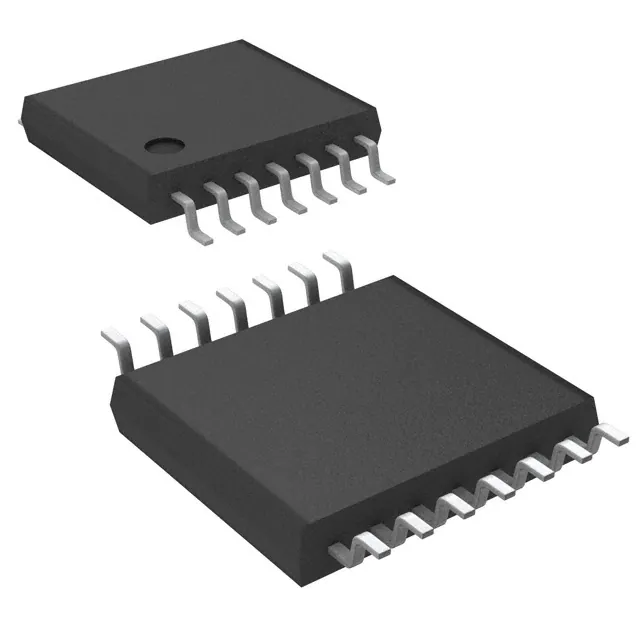
- Part No.:
- MCP2030-I/ST
- Manufacturer:
- Microchip Technology
- Category:
- RF Front End (LNA + PA)
- Package:
- 14-TSSOP (0.173", 4.40mm Width)
- Datasheet:
-
 MCP2030-I/ST.pdf
- Description:
- IC KEYLESS ENTRY AFE 14TSSOP
- Quantity:
- Payment:

- Shipping:

Inventory:192
Please send an inquiry. Send us your inquiry, and we will respond immediately.
Product details
Overview
MCP2030-I/ST from Microchip Technology is a three-channel low-frequency (125 kHz) analog front-end IC for bidirectional LF transponder communication, featuring 1 mVPP input sensitivity, programmable 63 pF antenna tuning per channel, and SPI-configurable output modes (demodulated data, carrier clock, or RSSI current). It enables passive keyless entry (PKE), engine immobilizer, and TPMS LF initiator functions in automotive and security systems.
For engineers reviewing the MCP2030-I/ST datasheet, MCP2030-I/ST pinout, MCP2030-I/ST application, or MCP2030-I/ST equivalent, this page delivers verified technical context, exact pin roles, real-world timing behavior of output enable filters, RSSI linearity specs, and validated alternatives for LF transponder AFE design.
Technical Context
The MCP2030-I/ST implements an analog signal chain with RF limiter, AGC, demodulator, and programmable output enable filter logic - all optimized for 125 kHz carrier detection and amplitude-modulated (AM) signal recovery down to 8% modulation depth. Its internal RC oscillator (32 kHz typical) drives timing-critical functions including AGC stabilization (4 ms), inactivity timer (16 ms), and nine configurable wake-up filters.
Each LC input channel (LCX/LCY/LCZ) features independent enable control, 63-step 1 pF/step tuning capacitance (0–63 pF ±30%), and high-impedance input (800 kΩ || 24 pF). The device supports battery-backed and batteryless operation via external circuitry and offers three output configurations routed through LFDATA/CCLK/SDIO and RSSI pins under register control.
Key Specifications
| Parameter | Value and Actual Design Meaning |
|---|---|
| Carrier frequency | 125 kHz - fixed center frequency for LF transponder interrogation; defines resonant antenna design target. |
| Input sensitivity | 1 mVPP (min) - enables reliable detection of weak signals from distant or misaligned transponders. |
| Modulation depth support | 8% (min) - allows decoding of low-depth AM signals common in PKE and immobilizer protocols. |
| Active current (3 ch) | 13 µA typical at 3.0 V - ultra-low power enables multi-year battery life in passive transponder initiators. |
| Standby current (3 ch) | 4 µA typical at 3.0 V - maintains readiness while minimizing quiescent drain during idle periods. |
| RSSI output linearity | ±15% error - provides predictable current-vs.-signal-strength mapping for proximity estimation and link quality monitoring. |
| SPI clock max | 3 MHz - supports fast register access for dynamic configuration during system wake-up or mode switching. |
Pinout & Package
The MCP2030-I/ST is housed in a 14-pin TSSOP package (4.4 mm × 5.0 mm, 0.65 mm pitch), with exposed pad not electrically connected. Pin 1 is marked by a dot; pins 5 and 12 are NC and must remain unconnected.
| Pin/Terminal | Circuit Role | Design Meaning |
|---|---|---|
| VSS (Pins 1, 14) | Ground reference | Common return path for analog/digital sections; requires low-impedance PCB ground plane connection. |
| CS (Pin 2) | Digital input / SPI mode selector | High = normal operation (LFDATA/RSSI active); low = SPI programming mode (SDIO bidirectional). |
| SCLK/ALERT (Pin 3) | Configurable I/O | When CS=low: SPI clock input; when CS=high: open-drain ALERT output indicating parity error or alarm timeout. |
| RSSI (Pin 4) | Analog current output | Sink current linearly proportional to input signal strength (0.65–100 µA over 0–4 VPP range). |
| LFDATA/CCLK/SDIO (Pin 6) | Configurable I/O | When CS=high: outputs demodulated NRZ data or divided carrier clock; when CS=low: SPI data I/O pin. |
| VDD (Pins 7, 8) | Power supply | 2.0–3.6 V analog/digital rail; requires 0.1 µF ceramic bypass capacitor per VDD pin. |
| LCX/LCY/LCZ (Pins 11, 10, 9) | LC antenna inputs | High-Z differential inputs (800 kΩ || 24 pF) for orthogonal x/y/z coil connections to LCCOM. |
| LCCOM (Pin 13) | Antenna common reference | Shared return node for all three LC resonant circuits; must be tied to VSS or external bias network. |
Key Features
| Feature | Design Value |
|---|---|
| Three independent LC input channels | Enables omnidirectional signal detection using orthogonally mounted antennas - critical for PKE fob localization without orientation dependency. |
| Programmable 63-step tuning capacitance (0–63 pF) | Permits fine-tuning of external LC tank resonance to compensate for component tolerances and PCB parasitics at 125 kHz. |
| Nine configurable output enable filters | Provides selectable wake-up timing windows (1–10 ms total period) to reject noise bursts and ensure valid transponder response detection. |
| Battery-backup and batteryless operation support | Allows integration into energy-harvesting or capacitor-powered systems using external diode/capacitor networks - no dedicated battery required. |
| AGC stabilization time of 4 ms | Ensures rapid gain convergence before demodulation begins, enabling consistent decoding across varying field strengths and coil coupling conditions. |
Applications
| Passive Keyless Entry (PKE) Transponder | Engine Immobilizer System |
|---|---|
|
Use Scenario: Vehicle detects driver's key fob within ~2 m radius upon door handle approach. IC Role / Device Role / Timing Role: MCP2030-I/ST acts as LF initiator AFE, receiving modulated 125 kHz challenge signal and returning encrypted response via load modulation. Use Value: 1 mVPP sensitivity extends detection range; 8% modulation depth support ensures compatibility with legacy fobs; 4 µA standby current enables multi-year battery life. |
Use Scenario: Ignition key inserted; vehicle verifies cryptographic authenticity before enabling starter motor. IC Role / Device Role / Timing Role: MCP2030-I/ST serves as secure LF interrogator, generating 125 kHz carrier and decoding encrypted transponder reply. Use Value: Programmable RSSI output validates coil coupling integrity; AGC stabilization ensures reliable decoding even with misaligned keys; SPI interface enables secure firmware updates. |
| LF Initiator for TPMS Sensors | Long-Range Access Control Transponder |
|
Use Scenario: Service tool activates dormant TPMS sensor inside tire to read pressure/temperature data. IC Role / Device Role / Timing Role: MCP2030-I/ST initiates LF burst, receives backscatter-modulated sensor ID and telemetry on LFDATA pin. Use Value: Three-channel input allows robust detection regardless of sensor orientation inside wheel well; low 13 µA active current minimizes handheld tool power consumption. |
Use Scenario: Driver approaches gated community entrance; transponder in vehicle triggers automatic gate opening at 3–5 m distance. IC Role / Device Role / Timing Role: MCP2030-I/ST functions as high-sensitivity LF receiver in gate controller, detecting encoded ID from vehicle-mounted tag. Use Value: 63 pF programmable tuning compensates for environmental drift in outdoor antenna installations; RSSI output enables adaptive gain control for variable distance operation. |
Equivalent & Alternatives
The following parts are listed as comparable options for similar LF transponder AFE applications.
| Alternative Part | Technical Difference | Application Difference | Selection Advice |
|---|---|---|---|
| TDK IAM-82024 | Single-channel 125 kHz AFE; integrated voltage regulator; no RSSI output; 2.5 µA standby current. | Optimized for compact, single-axis PKE systems where size and cost outweigh multi-directional coverage needs. | Select IAM-82024 only if orthogonal antenna layout is impractical and RSSI-based diagnostics are unnecessary. |
| NXP UCODE I2C | RFID tag IC (not initiator); passive UHF (860–960 MHz); no LF receive capability; requires external reader. | Used in asset tracking tags, not in vehicle-side LF interrogation hardware. | UCODE I2C is not functionally comparable - it is a tag, not an initiator AFE; avoid for MCP2030-I/ST replacement scenarios. |
Compared with IAM-82024 and UCODE I2C, the MCP2030-I/ST uniquely delivers three-channel directional sensing, programmable RSSI, and SPI-configurable output modes - making it the only viable choice for automotive-grade PKE initiators requiring omnidirectional reliability and diagnostic feedback.
Availability
MCP2030-I/ST is available at Aetrix Electronics and suitable for Passive Keyless Entry (PKE), engine immobilizer, and LF-initiated Tire Pressure Monitoring Systems (TPMS) requiring stable component supply across automotive production lifecycles.
Supply support for MCP2030-I/ST includes scheduled delivery planning, volume procurement assistance, BOM continuity management, traceable sourcing, and lifecycle availability coordination for OEM customers, industrial embedded developers, connected-device designers, and electronics production programs.
Manufacturer
Microchip Technology is a global semiconductor manufacturer specializing in microcontrollers, analog devices, and interface ICs, with deep expertise in automotive and secure identification solutions.
The MCP2030 product line was designed specifically for low-power, high-sensitivity LF transponder initiation in automotive security and wireless sensing - targeting PKE, immobilizer, and TPMS applications with stringent current and timing requirements.
FAQ
What is the primary function of the MCP2030-I/ST in a Passive Keyless Entry system?
The MCP2030-I/ST serves as the analog front-end initiator in Passive Keyless Entry systems, generating and receiving 125 kHz LF signals to authenticate and locate the key fob. It detects modulated carrier signals as low as 1 mVPP, demodulates responses, and outputs decoded data or RSSI current via the LFDATA and RSSI pins - enabling hands-free door unlocking without user interaction. Its three-channel architecture ensures reliable detection regardless of fob orientation.
How does the MCP2030-I/ST achieve ultra-low power consumption in standby mode?
The MCP2030-I/ST achieves 4 µA typical standby current (with all three channels enabled) through integrated power-gating logic, sleep-state optimization of its internal RC oscillator (32 kHz), and selective disabling of analog blocks when no signal is present. Its inactivity timer (16 ms) automatically transitions to deeper sleep after signal absence, and the device supports external battery-backup circuitry to maintain state during main power loss - all critical for multi-year battery life in automotive key fobs and portable tools.
Can the MCP2030-I/ST be used with different LC antenna configurations, and how is tuning handled?
Yes - the MCP2030-I/ST supports three independent LC inputs (LCX, LCY, LCZ) for orthogonal antenna placement, and each channel includes programmable tuning capacitance from 0 to 63 pF in 1 pF steps. This allows precise compensation for manufacturing tolerances and PCB parasitics in external 125 kHz resonant tanks. Tuning is configured via Configuration Registers 1–3, enabling field calibration without hardware changes - essential for maintaining resonance accuracy across temperature and unit variance.
What output modes does the MCP2030-I/ST support, and how are they selected?
The MCP2030-I/ST supports three output modes: demodulated NRZ data, divided carrier clock (carrier/1 or carrier/4), and RSSI current - all selectable via Configuration Register 4. Demodulated data and carrier clock share the LFDATA/CCLK/SDIO pin (Pin 6), while RSSI is output exclusively on Pin 4. Mode selection occurs dynamically via SPI writes, allowing runtime adaptation - for example, switching to carrier clock output during antenna tuning verification or RSSI during link quality assessment in the MCP2030-I/ST.
Does the MCP2030-I/ST require external components for basic operation, and what are the critical ones?
Yes - the MCP2030-I/ST requires external components for stable operation: two 0.1 µF ceramic bypass capacitors (one per VDD pin), three LC resonant antennas (each connected between LCX/LCY/LCZ and LCCOM), and pull-up resistors on ALERT and CS if interfacing with open-drain logic. For batteryless operation, a diode-capacitor energy harvesting network is needed on VDD. The internal tuning capacitors eliminate need for external trimmers, but external coil Q-factor and layout parasitics directly impact sensitivity and must be controlled per Microchip's layout guidelines for the MCP2030-I/ST.
MCP2030-I/ST Specifications
- Product attributes
- Attribute value
- Manufacturer:
- Microchip Technology
- Series:
- -
- Packaging:
- Tube
- Product Status:
- Active
- RF Type:
- General Purpose
- Frequency:
- 125kHz
- Features:
- 10kbps
- Grade:
- -
- Qualification:
- -
- Supplier Device Package:
- 14-TSSOP
MCP2030-I/ST FAQ
1.How can I place an order for MCP2030-I/ST through Aetrix?
Please submit a Request for Quotation (RFQ) for MCP2030-I/ST on Aetrix. Our sales agent will provide a competitive quotation and guide you through the order confirmation once you accept the terms.
2.Are the price and stock information for MCP2030-I/ST reliable?
The price and inventory of MCP2030-I/ST are updated periodically and may fluctuate due to market conditions. Stock and pricing data are typically refreshed every 24 hours. Quotation validity for MCP2030-I/ST is usually 5 days.
3.What payment methods are accepted for MCP2030-I/ST?
We accept Wire Transfer, PayPal, Credit Card, Western Union, MoneyGram, and Escrow for MCP2030-I/ST transactions.
Note: Certain payment methods may incur a processing fee.
4.How is shipping managed for MCP2030-I/ST?
MCP2030-I/ST orders can be shipped via leading logistics carriers, including DHL, UPS, FedEx, TNT, or Registered Mail.
Once your MCP2030-I/ST order is processed, you will receive an email with the shipment details and tracking number.
Note: Tracking information may take up to 24 hours to appear. Express delivery typically takes 3–5 business days.
5.How can I obtain technical support or documentation for MCP2030-I/ST?
For technical support, including MCP2030-I/ST datasheets, pinout diagrams, or application guidance, please contact our engineering support team. They can provide detailed documentation and assistance for your MCP2030-I/ST requirements.
6.How does Aetrix verify that MCP2030-I/ST is sourced from the original manufacturer or authorized distributors?
All MCP2030-I/ST products on Aetrix are procured from qualified distributors and authorized channels. Our dedicated quality assurance team conducts strict verification, including traceability checks and, if necessary, third-party testing. This ensures that MCP2030-I/ST meets industry standards.
7.What is the process for return or replacement of MCP2030-I/ST?
All MCP2030-I/ST units undergo pre-shipment inspection (PSI). If there is an issue with MCP2030-I/ST, returns or replacements are accepted under the following conditions:
1.Quantity discrepancies, incorrect items, or visible external defects (such as breakage or corrosion), acknowledged by Aetrix.
2.The issue is reported within 90 days of delivery.
3.The MCP2030-I/ST part is unused and in its original packaging.
Return procedure for MCP2030-I/ST:
1.Submit a request within 90 days.
2.Obtain a Return Material Authorization (RMA) from Aetrix.
MCP2030-I/ST Tags
-
RFX2401C
Skyworks Solutions Inc.
.jpg)
-
NRF21540-QDAA-R
Nordic Semiconductor ASA
-
NRF21540-QDAA-R7
Nordic Semiconductor ASA
-
RFX2411N
Skyworks Solutions Inc.
-
SE2438T-R
Skyworks Solutions Inc.
-
SKY66118-11
Skyworks Solutions Inc.
-
SKY85712-21
Skyworks Solutions Inc.

-
SKY85329-11
Skyworks Solutions Inc.
-
SKY66422-11
Skyworks Solutions Inc.

-
SKY66119-11
Skyworks Solutions Inc.
-
NJG1156PCD-TE1
Nisshinbo Micro Devices Inc.
-
SE2435L-R
Skyworks Solutions Inc.
Tech Hub

TTL and CMOS logic families differ in thresholds, loading, output drive, power and timing. This engineering guide compares 74HC and 74HCT, calculates noise margins and checks 3.3 V/5 V compatibility.

A practical engineering guide to 3.3V and 5V logic compatibility, input thresholds, resistor dividers, translator ICs, MOSFET level shifting, I2C pull-ups, timing limits and power-sequencing risks.

The 74HC595 uses push-pull logic outputs, while the TPIC6B595 uses 50 V open-drain DMOS sinks for higher-power loads. This guide compares timing, current limits, 3.3 V interfacing, load wiring, thermal…

The 74HC595 converts serial data into eight stable parallel outputs. This guide covers pin functions, shift and storage timing, OE and MR behavior, drive-current limits, cascading, voltage compatibilit…

A technical comparison of level-sensitive latches and edge-triggered flip-flops, covering timing windows, setup and hold limits, master–slave operation, time borrowing, race-through, HDL inference and…

A D latch stores one bit while Enable controls when data can pass. This reference covers gate-level operation, truth tables, transparency, setup and hold timing, LE versus OE, common ICs and practical …

An SR latch stores one bit through cross-coupled feedback. This engineering reference covers NOR and NAND implementations, truth tables, forbidden-state recovery, gated operation, switch debouncing, fa…

Latch circuits retain one bit through feedback. This technical reference covers SR and D latches, truth tables, transparency, timing limits, latch-versus-flip-flop behavior, applications and common log…

An engineering guide to LED driver operation, constant-current and constant-voltage outputs, linear and switching topologies, dimming, IC selection, calculations, replacement compatibility, and fault c…

Operational amplifier guide covering op amp basics, feedback, ideal vs real op amps, common configurations, buffer circuits, offset, bias current, gain-bandwidth, slew rate, rail-to-rail limits and sel…


