
 My Inquiry
 My Account


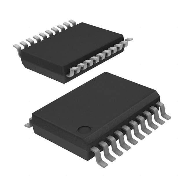
Microchip Technology MCP23008-E/SS
- Part No.:
- MCP23008-E/SS
- Manufacturer:
- Microchip Technology
- Category:
- I/O Expanders
- Package:
- 20-SSOP (0.209", 5.30mm Width)
- Datasheet:
-
 MCP23008-E/SS.pdf
- Description:
- IC XPNDR 1.7MHZ I2C 20SSOP
- Quantity:
- Payment:

- Shipping:

Inventory:2,117
Please send an inquiry. Send us your inquiry, and we will respond immediately.
Product details
Overview
MCP23008-E/SS from Microchip Technology is an 8-bit I²C-compatible I/O expander IC designed to extend microcontroller GPIO resources in space-constrained embedded systems. It provides bidirectional I/O pins (GP0–GP7), configurable interrupt output (INT), hardware address inputs (A2:A0), and operates from 1.8V to 5.5V across –40°C to +85°C. Used in industrial control panels for remote sensor interface and LED status bank expansion.
For engineers reviewing the MCP23008-E/SS datasheet, MCP23008-E/SS pinout, MCP23008-E/SS application, or MCP23008-E/SS equivalent, key selection criteria include I²C bus speed support (up to 1.7 MHz), low standby current (1 µA max), interrupt-on-change capability with DEFVAL/INTCON register control, and SSOP-20 package compatibility with standard 0.65 mm pitch PCB layouts.
Technical Context
The MCP23008-E/SS implements a fully register-mapped I²C slave interface with eleven 8-bit configuration registers (IODIR, IPOL, GPINTEN, DEFVAL, INTCON, IOCON, GPPU, INTF, INTCAP, GPIO, OLAT) accessible via 7-bit slave address (0x20–0x27). Its interrupt logic supports two mutually exclusive modes: pin-change detection or comparison against programmable DEFVAL register values.
Internal weak pull-up resistors (100 kΩ) per GPIO pin are software-configurable via GPPU register; polarity inversion is supported per-pin via IPOL register; and output latches (OLAT) decouple read-modify-write operations from physical pin states. The device features Power-on Reset (POR) and external RESET input for deterministic initialization.
Key Specifications
| Parameter | Value and Actual Design Meaning |
|---|---|
| I²C Speed | Supports 100 kHz, 400 kHz, and 1.7 MHz modes - enables high-throughput peripheral expansion without CPU polling overhead. |
| Supply Voltage Range | 1.8V to 5.5V at –40°C to +85°C - interoperable with 1.8V logic families and legacy 5V systems. |
| Standby Current | 1 µA maximum - critical for battery-powered IoT nodes requiring multi-year operation. |
| GPIO Count | 8 bidirectional I/O pins (GP0–GP7) with individual direction, polarity, pull-up, and interrupt enable control - enables flexible signal routing and mixed-signal interfacing. |
| Interrupt Output | Configurable active-high, active-low, or open-drain INT pin - simplifies integration with diverse host interrupt controllers and level-shifting requirements. |
| Hardware Address Pins | A2, A1, A0 allow up to eight devices on same I²C bus - eliminates address conflicts in multi-peripheral systems like HVAC controllers. |
| Package | 20-pin SSOP (0.65 mm pitch) - surface-mount compatible with automated assembly and moderate-density PCB layouts. |
Pinout & Package
20-pin SSOP (Shrink Small Outline Package), 0.65 mm lead pitch, body width 5.3 mm, compliant with JEDEC MO-153.
| Pin/Terminal | Circuit Role | Design Meaning |
|---|---|---|
| 1 (SDA) | I²C data line | Open-drain bidirectional serial data I/O; requires external pull-up resistor (typically 4.7 kΩ). |
| 2 (SCL) | I²C clock line | Input-only clock signal; synchronizes all register reads/writes and interrupt timing. |
| 3 (NC) | No-connect | Internally unconnected; must be left floating or tied to VSS/VDD per layout best practice. |
| 4 (INT) | Interrupt output | Active-low, open-drain interrupt flag; asserts when enabled GPIO pins change state or differ from DEFVAL. |
| 5 (RESET) | External reset input | Active-low asynchronous reset; forces all registers to POR defaults and clears interrupt flags. |
| 6 (A1) | Hardware address bit | LSB of 3-bit I²C slave address; biased externally to VDD or VSS to select one of eight possible addresses (0x20–0x27). |
| 7 (GP4) | General-purpose I/O | Bidirectional pin with configurable direction, polarity, weak pull-up, and interrupt-on-change enable. |
| 8 (VDD) | Power supply | Primary power rail (1.8–5.5V); bypass capacitor (100 nF) required near pin for noise immunity. |
| 9 (GP7) | General-purpose I/O | Highest-numbered GPIO; identical functionality to GP0–GP6 including interrupt capture in INTCAP register. |
| 10 (GP6) | General-purpose I/O | Supports simultaneous interrupt monitoring with GP5–GP0; state captured in INTCAP on first interrupt event. |
| 11 (GP5) | General-purpose I/O | Configurable as input with DEFVAL-based interrupt or output driving LEDs/relays up to 25 mA sink/source. |
| 12 (GP3) | General-purpose I/O | Shared with internal weak pull-up control (GPPU register); used for switch sensing with debouncing via software. |
| 13 (GP2) | General-purpose I/O | Supports polarity inversion (IPOL register) to match inverted sensor outputs without external inverters. |
| 14 (GP1) | General-purpose I/O | Output latch (OLAT) decouples write operations from real-time pin state - prevents glitches during multi-bit updates. |
| 15 (GP0) | General-purpose I/O | Default input at power-up (IODIR = 0xFF); primary pin for initial system bring-up and debug signaling. |
| 16 (A0) | Hardware address bit | MSB of 3-bit I²C address; combined with A1 and A2 to form full 7-bit slave address prefix (0b0100xxx). |
| 17 (N/C) | No-connect | Unused internal bond pad; electrically isolated - no external connection required. |
| 18 (A1) | Hardware address bit | Middle bit of 3-bit address; determines device uniqueness within shared I²C segment (e.g., sensor hub + display driver). |
| 19 (RESET) | External reset input | Duplicate RESET pin for mechanical redundancy in high-reliability designs; both pins function identically. |
| 20 (INT) | Interrupt output | Duplicate INT pin for fanout flexibility; both pins mirror same interrupt logic state and require common pull-up. |
Key Features
| Feature | Design Value |
|---|---|
| Register-mapped I²C interface | Eleven 8-bit control registers (e.g., IODIR, GPINTEN, DEFVAL) enable precise per-pin configuration without firmware abstraction layers. |
| Interrupt-on-change with capture | INTCAP register preserves port state at interrupt trigger time - eliminates race conditions when host reads GPIO after interrupt assertion. |
| Configurable interrupt polarity & drive | IOCON register bits (ODR, INTPOL) let INT pin operate as push-pull active-high, push-pull active-low, or open-drain - matches host MCU's interrupt controller requirements. |
| Individual GPIO polarity inversion | IPOL register allows each GPx pin to invert input logic (e.g., active-low switch → high in GPIO register) - removes need for external inverters in mixed-signal interfaces. |
| Software-controllable weak pull-ups | GPPU register enables/disables 100 kΩ internal pull-ups per pin - reduces BOM count and PCB area versus discrete resistors for button/switch interfaces. |
Applications
| Industrial HMI Panel | Smart Energy Meter |
|---|---|
Use Scenario: Expanding microcontroller GPIO to drive 8-channel LED status indicators and read 8 tactile buttons on a factory floor operator interface. IC Role / Device Role / Timing Role: I/O expander providing parallel-to-serial conversion via I²C; handles debounced switch reads and LED current sinking (25 mA/pin) without MCU intervention. Use Value: Reduces main MCU pin count requirement by 8, enables independent interrupt-driven button response, and supports 1.7 MHz I²C for <10 µs register access latency. | Use Scenario: Monitoring tamper-detection switches and controlling relay drivers in a DIN-rail mounted electricity meter with strict power budget. IC Role / Device Role / Timing Role: Low-power I/O hub managing security inputs and isolation outputs; uses standby current ≤1 µA to meet IEC 62056-21 Class C energy consumption limits. Use Value: Eliminates need for discrete level shifters and pull-ups, integrates interrupt-driven tamper alerting with DEFVAL/INTCON register matching, and operates reliably from 1.8V battery backup. |
| Automotive Body Control Module | IoT Sensor Aggregator |
Use Scenario: Adding diagnostic LED banks and door-lock actuator feedback signals to a CAN-connected BCM with limited native GPIO. IC Role / Device Role / Timing Role: Robust I²C peripheral extending MCU I/O while meeting AEC-Q100 stress test requirements via wide temperature range (–40°C to +85°C) and ESD tolerance. Use Value: Hardware address pins (A2:A0) allow daisy-chaining up to eight expanders on single I²C bus - scales I/O count linearly without additional MCU pins or buses. | Use Scenario: Consolidating analog sensor alerts (temperature, humidity, motion) into a single I²C node for wireless transmission in a battery-powered environmental monitor. IC Role / Device Role / Timing Role: Event-driven I/O concentrator using interrupt-on-change to wake host MCU only when sensor thresholds are crossed - minimizes active time and extends battery life. Use Value: INTCAP register captures exact sensor state at interrupt time, enabling accurate edge-triggered logging without continuous polling or timestamp interpolation. |
Equivalent & Alternatives
The following parts are listed as comparable options for similar I/O expansion applications.
| Alternative Part | Technical Difference | Application Difference | Selection Advice |
|---|---|---|---|
| PCA9554APW,118 | 8-bit I²C expander with identical 20-pin TSSOP package but lacks DEFVAL/INTCON interrupt comparison mode - only supports basic pin-change interrupts. | Less suitable for applications requiring masked interrupt triggers (e.g., ignoring noise on specific lines) due to absence of DEFVAL register. | Select PCA9554APW,118 only if interrupt logic simplicity and NXP supply chain preference outweigh advanced interrupt configurability. |
| TCA6408APWR | 8-bit I²C expander with 16-pin TSSOP package, lower max I²C speed (400 kHz), and no hardware address pins - fixed I²C address (0x20) limits multi-device deployment. | Appropriate for single-expander systems where board space is constrained and bus arbitration is not required. | Choose TCA6408APWR when footprint reduction (16-pin vs. 20-pin) and TI ecosystem alignment justify loss of address flexibility and reduced interrupt feature set. |
Compared with PCA9554APW,118 and TCA6408APWR, the MCP23008-E/SS uniquely delivers three hardware address pins for multi-drop I²C scalability, 1.7 MHz high-speed mode for low-latency control loops, and dual-mode interrupt logic (pin-change or DEFVAL-comparison) essential for robust industrial sensing.
Availability
MCP23008-E/SS is available at Aetrix Electronics and suitable for industrial HMI panels, smart energy meters, automotive body control modules, and IoT sensor aggregators requiring stable component supply across extended temperature ranges and long production lifecycles.
Supply support for MCP23008-E/SS includes scheduled delivery planning, volume procurement assistance, BOM continuity management, traceable sourcing, and lifecycle availability coordination for OEM customers, industrial embedded developers, connected-device designers, and electronics production programs.
Manufacturer
Microchip Technology Inc. is a leading provider of microcontrollers, analog components, and Flash-IP solutions, headquartered in Chandler, Arizona, with global design and manufacturing operations.
The MCP23X08 product line was engineered specifically for cost-sensitive, space-constrained embedded systems needing scalable I/O expansion via industry-standard I²C or SPI interfaces - targeting industrial automation, building controls, and consumer electronics.
FAQ
What is the maximum I²C clock frequency supported by the MCP23008-E/SS?
The MCP23008-E/SS supports I²C operation at 100 kHz, 400 kHz, and up to 1.7 MHz under specified voltage and temperature conditions. At 1.7 MHz, operation is guaranteed only within the 4.5V–5.5V VDD range and –40°C to +125°C ambient, making it suitable for high-throughput industrial control loops where low-latency register access is critical. The MCP23008-E/SS achieves this speed through optimized internal clock synchronization and slew-rate-controlled SDA output.
How does the interrupt-on-change functionality work in the MCP23008-E/SS?
The MCP23008-E/SS interrupt-on-change logic operates in two mutually exclusive modes controlled by the INTCON register: either comparing input states against previous values (default) or against programmable DEFVAL register contents. When enabled via GPINTEN, any qualifying pin transition asserts the INT pin. The INTCAP register captures the exact port state at interrupt trigger time, and the interrupt remains asserted until INTCAP or GPIO is read - ensuring no event loss during host processing. This behavior is fully implemented in the MCP23008-E/SS silicon.
Can the MCP23008-E/SS operate from a 1.8V supply?
Yes, the MCP23008-E/SS is fully specified to operate from 1.8V to 5.5V over the industrial temperature range (–40°C to +85°C). At 1.8V, it supports I²C speeds up to 100 kHz and maintains all functional features including GPIO direction control, interrupt generation, weak pull-up activation, and register read/write operations. Input thresholds scale with VDD, and the internal POR circuit ensures reliable reset across the entire voltage range - confirmed in DS20001919F Section 2.1 DC Characteristics.
What package type does the MCP23008-E/SS use, and is it RoHS compliant?
The MCP23008-E/SS uses a 20-pin SSOP (Shrink Small Outline Package) with 0.65 mm lead pitch and is RoHS compliant per Microchip's official product change notice (PCN# 170201A). The package meets JEDEC MO-153 standards, features matte tin lead finish, and supports standard reflow profiles including J-STD-020D. Pin 1 identifier is marked with a dot; thermal pad is absent - consistent with the SSOP variant documented in DS20001919F page 2.
Does the MCP23008-E/SS include internal pull-up resistors on its GPIO pins?
Yes, the MCP23008-E/SS includes software-configurable internal weak pull-up resistors (100 kΩ typical) on all eight GPIO pins (GP0–GP7). These are enabled or disabled individually via the GPPU register bits. Pull-ups are active only when the corresponding pin is configured as an input (IODIR bit = 1) and have no effect on output pins. This feature eliminates external pull-up resistors in switch/button interfaces and is verified in DS20001919F Section 1.6.7 and Electrical Characteristics table D070.
MCP23008-E/SS Specifications
- Product attributes
- Attribute value
- Manufacturer:
- Microchip Technology
- Series:
- -
- Package/Case:
- 20-SSOP (0.209", 5.30mm Width)
- Packaging:
- Tube
- Product Status:
- Active
- Programmable:
- Not Verified
- Number of I/O:
- 8
- Interface:
- I2C
- Interrupt Output:
- Yes
- Features:
- POR
- Output Type:
- Push-Pull
- Current - Output Source/Sink:
- 25mA
- Clock Frequency:
- 1.7 MHz
- Voltage - Supply:
- 1.8V ~ 5.5V
- Operating Temperature:
- -40°C ~ 125°C
- Grade:
- -
- Qualification:
- -
- Mounting Type:
- Surface Mount
- Supplier Device Package:
- 20-SSOP
MCP23008-E/SS FAQ
1.How can I place an order for MCP23008-E/SS through Aetrix?
Please submit a Request for Quotation (RFQ) for MCP23008-E/SS on Aetrix. Our sales agent will provide a competitive quotation and guide you through the order confirmation once you accept the terms.
2.Are the price and stock information for MCP23008-E/SS reliable?
The price and inventory of MCP23008-E/SS are updated periodically and may fluctuate due to market conditions. Stock and pricing data are typically refreshed every 24 hours. Quotation validity for MCP23008-E/SS is usually 5 days.
3.What payment methods are accepted for MCP23008-E/SS?
We accept Wire Transfer, PayPal, Credit Card, Western Union, MoneyGram, and Escrow for MCP23008-E/SS transactions.
Note: Certain payment methods may incur a processing fee.
4.How is shipping managed for MCP23008-E/SS?
MCP23008-E/SS orders can be shipped via leading logistics carriers, including DHL, UPS, FedEx, TNT, or Registered Mail.
Once your MCP23008-E/SS order is processed, you will receive an email with the shipment details and tracking number.
Note: Tracking information may take up to 24 hours to appear. Express delivery typically takes 3–5 business days.
5.How can I obtain technical support or documentation for MCP23008-E/SS?
For technical support, including MCP23008-E/SS datasheets, pinout diagrams, or application guidance, please contact our engineering support team. They can provide detailed documentation and assistance for your MCP23008-E/SS requirements.
6.How does Aetrix verify that MCP23008-E/SS is sourced from the original manufacturer or authorized distributors?
All MCP23008-E/SS products on Aetrix are procured from qualified distributors and authorized channels. Our dedicated quality assurance team conducts strict verification, including traceability checks and, if necessary, third-party testing. This ensures that MCP23008-E/SS meets industry standards.
7.What is the process for return or replacement of MCP23008-E/SS?
All MCP23008-E/SS units undergo pre-shipment inspection (PSI). If there is an issue with MCP23008-E/SS, returns or replacements are accepted under the following conditions:
1.Quantity discrepancies, incorrect items, or visible external defects (such as breakage or corrosion), acknowledged by Aetrix.
2.The issue is reported within 90 days of delivery.
3.The MCP23008-E/SS part is unused and in its original packaging.
Return procedure for MCP23008-E/SS:
1.Submit a request within 90 days.
2.Obtain a Return Material Authorization (RMA) from Aetrix.
MCP23008-E/SS Tags
-
TCA6408ARSVR
Texas Instruments

-
TCA9535RTWR
Texas Instruments
-
FXL6408UMX
onsemi

-
PCF8574ADWR
Texas Instruments

-
PCF8574APWR
Texas Instruments
-
TCA9555PWR
Texas Instruments

-
TCA9554PWR
Texas Instruments
-
TCA9554APWR
Texas Instruments

-
TCA9539PWR
Texas Instruments
-
TCA9534PWR
Texas Instruments
-
TCA9555RTWR
Texas Instruments
-
TCA9535PWR
Texas Instruments
Tech Hub

TTL and CMOS logic families differ in thresholds, loading, output drive, power and timing. This engineering guide compares 74HC and 74HCT, calculates noise margins and checks 3.3 V/5 V compatibility.

A practical engineering guide to 3.3V and 5V logic compatibility, input thresholds, resistor dividers, translator ICs, MOSFET level shifting, I2C pull-ups, timing limits and power-sequencing risks.

The 74HC595 uses push-pull logic outputs, while the TPIC6B595 uses 50 V open-drain DMOS sinks for higher-power loads. This guide compares timing, current limits, 3.3 V interfacing, load wiring, thermal…

The 74HC595 converts serial data into eight stable parallel outputs. This guide covers pin functions, shift and storage timing, OE and MR behavior, drive-current limits, cascading, voltage compatibilit…

A technical comparison of level-sensitive latches and edge-triggered flip-flops, covering timing windows, setup and hold limits, master–slave operation, time borrowing, race-through, HDL inference and…

A D latch stores one bit while Enable controls when data can pass. This reference covers gate-level operation, truth tables, transparency, setup and hold timing, LE versus OE, common ICs and practical …

An SR latch stores one bit through cross-coupled feedback. This engineering reference covers NOR and NAND implementations, truth tables, forbidden-state recovery, gated operation, switch debouncing, fa…

Latch circuits retain one bit through feedback. This technical reference covers SR and D latches, truth tables, transparency, timing limits, latch-versus-flip-flop behavior, applications and common log…

An engineering guide to LED driver operation, constant-current and constant-voltage outputs, linear and switching topologies, dimming, IC selection, calculations, replacement compatibility, and fault c…

Operational amplifier guide covering op amp basics, feedback, ideal vs real op amps, common configurations, buffer circuits, offset, bias current, gain-bandwidth, slew rate, rail-to-rail limits and sel…


