
 My Inquiry
 My Account


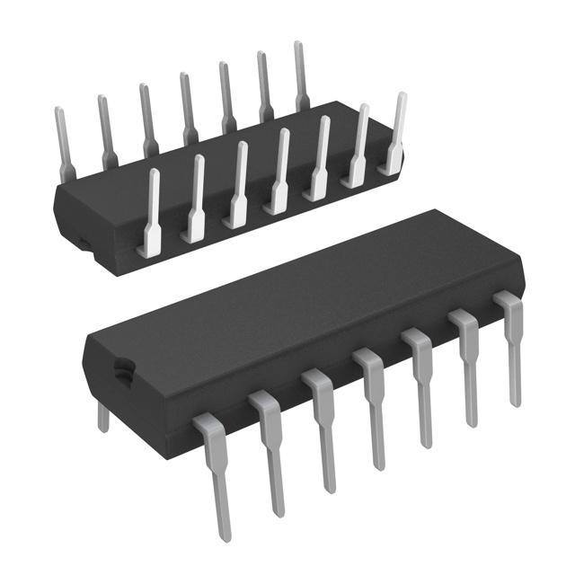
Microchip Technology MCP25020-I/P
- Part No.:
- MCP25020-I/P
- Manufacturer:
- Microchip Technology
- Category:
- I/O Expanders
- Package:
- 14-DIP (0.300", 7.62mm)
- Datasheet:
-
 MCP25020-I/P.pdf
- Description:
- IC XPNDR 25MHZ CAN V2.0B 14DIP
- Quantity:
- Payment:

- Shipping:

Inventory:1,899
Please send an inquiry. Send us your inquiry, and we will respond immediately.
Product details
Overview
MCP25020-I/P from Microchip Technology is a CAN v2.0B I/O expander IC that implements a complete CAN node without requiring an external microcontroller. It features three auto-transmit buffers, two message reception buffers, one programmable acceptance mask, two programmable filters, and eight general-purpose I/O lines - all operating at up to 1 Mb/s on industrial-temperature (-40°C to +85°C) CAN networks in automotive body control and industrial sensor monitoring applications.
For engineers reviewing the MCP25020-I/P datasheet, MCP25020-I/P pinout, MCP25020-I/P application, or MCP25020-I/P equivalent, this device serves as a self-contained CAN peripheral with configurable digital I/O, edge-triggered transmission, non-volatile configuration memory, and hardware-based error management - enabling rapid deployment in distributed I/O systems where MCU resources are constrained.
Technical Context
The MCP25020-I/P integrates a full CAN protocol engine with finite-state machine–driven bit timing logic, CRC generation/checking, and dual-error counters (TEC/REC) supporting Error-Active, Error-Passive, and Bus-Off states. Its CAN module includes double-buffered receive paths, programmable time quanta segmentation (SyncSeg, PropSeg, PS1, PS2), and resynchronization via configurable SJW (1–4 TQ).
It operates as a standalone CAN node: input messages modify internal registers and trigger Command Acknowledge responses; Information Request messages elicit output data frames; and On Bus messages transmit scheduled GPIO status. Configuration is stored in non-volatile memory and auto-loaded at power-up - eliminating boot firmware requirements.
Key Specifications
| Parameter | Value and Actual Design Meaning |
|---|---|
| CAN Compliance | CAN v2.0B active mode - supports standard and extended identifiers with full protocol handling including arbitration, error signaling, and automatic retransmission. |
| Max Bit Rate | 1 Mb/s - enables real-time communication in high-speed automotive and industrial control networks with minimal latency. |
| Supply Voltage | 2.7V to 5.5V - allows direct interface with 3.3V or 5V logic domains without level-shifting circuitry. |
| Active Current | 10 mA typical - ensures low power consumption during continuous bus operation in battery-backed or energy-sensitive nodes. |
| Standby Current | 30 µA in CAN Sleep mode - supports ultra-low-power wake-on-bus-traffic or pin-change functionality for always-on monitoring. |
| I/O Lines | 8 GP I/O pins - each individually configurable as input or output, with optional transmit-on-pin-change behavior for event-driven reporting. |
| Package | 14-pin PDIP (300 mil) - through-hole package suitable for prototyping, legacy industrial PCBs, and manual assembly environments. |
Pinout & Package
14-pin PDIP (300 mil) package with industry-standard footprint and lead spacing. RoHS-compliant, leaded construction for reliable solder joint formation and thermal cycling performance.
| Pin/Terminal | Circuit Role | Design Meaning |
|---|---|---|
| GP0/AN0 | Digital I/O / Analog input (not used) | General-purpose bidirectional TTL I/O; AN0 function disabled in MCP25020 variant per datasheet Table 1-1 footnote. |
| GP1/AN1 | Digital I/O / Analog input (not used) | General-purpose bidirectional TTL I/O; AN1 function disabled in MCP25020 variant. |
| GP2/AN2/PWM1 | Digital I/O / PWM output (not used) | General-purpose bidirectional TTL I/O; AN2 and PWM1 functions disabled in MCP25020 variant. |
| GP3/AN3/PWM2 | Digital I/O / PWM output (not used) | General-purpose bidirectional TTL I/O; AN3 and PWM2 functions disabled in MCP25020 variant. |
| GP4/VREF- | Digital I/O / Reference ground | Bidirectional I/O pin; VREF- not active - no analog subsystem present in MCP25020. |
| GP5/VREF+ | Digital I/O / Reference voltage | Bidirectional I/O pin; VREF+ not active - no analog subsystem present in MCP25020. |
| VSS | Ground | Primary digital ground reference for internal logic and CAN transceiver interface. |
| OSC1/CLKIN | Oscillator input | Accepts external crystal (1–20 MHz) or clock source to drive internal timing generator for CAN bit timing and system clocks. |
| OSC2 | Oscillator output | Crystal oscillator feedback output; unused when external clock is applied to OSC1. |
| GP6/CLKOUT | Digital I/O / Clock output | Bidirectional I/O; CLKOUT function provides buffered system clock for synchronization of external peripherals. |
| GP7/RST/VPP | Reset input / Programming voltage | Active-low reset input; VPP function reserved for In-Circuit Serial Programming™ but not used in standard operation. |
| RXCAN | CAN receive input | Differential CAN bus receive signal input - connects to CAN transceiver RX line; not connected in 1-wire mode (not supported on MCP25020). |
| TXCAN/TXRXCAN | CAN transmit output | Differential CAN bus transmit signal output - connects to CAN transceiver TX line; TXRXCAN alternate function is exclusive to MCP250X5 devices. |
| VDD | Power supply | Primary power rail (2.7–5.5V); powers internal logic, CAN controller, and I/O buffers. |
Key Features
| Feature | Design Value |
|---|---|
| Non-volatile configuration memory | Stores user-defined CAN IDs, filters, masks, and I/O settings - eliminates boot-time initialization and enables plug-and-play deployment. |
| Auto-transmit on digital edge detection | Each GP I/O can independently trigger transmission of predefined messages upon rising/falling edge - enables responsive fault reporting without host polling. |
| Three prioritized transmit buffers | Dedicated TXID0 (On Bus), TXID1 (Command Acknowledge/Error), TXID2 (edge/threshold events) - ensures deterministic message scheduling and priority-based bus arbitration. |
| Hardware error management | Integrated TEC/REC counters with automatic state transitions (Error-Active → Error-Passive → Bus-Off) and 128×11-bit auto-recovery - reduces software overhead for bus health monitoring. |
| Self-configuring CAN node | No external MCU required - handles CAN protocol framing, CRC, ACK, retransmission, and filtering autonomously after power-up. |
Applications
| Automotive Body Control | Industrial Sensor Node |
|---|---|
Use Scenario: Monitoring door lock status, window position, and mirror adjustment switches across multiple vehicle zones via CAN bus. IC Role / Device Role / Timing Role: Standalone CAN node collecting discrete switch inputs and transmitting status updates at configurable intervals or on change-of-state. Use Value: Eliminates need for dedicated microcontroller per zone - reduces BOM cost and board space while maintaining deterministic CAN timing and error resilience. |
Use Scenario: Remote temperature/humidity sensor unit with local digital inputs (e.g., alarm triggers, maintenance switches) in factory automation. IC Role / Device Role / Timing Role: CAN I/O concentrator aggregating local digital signals and reporting via scheduled or event-driven CAN frames. Use Value: Enables direct integration into existing CAN-based SCADA systems without gateway firmware development or protocol translation layers. |
| Building HVAC Zone Controller | Medical Equipment Status Monitor |
Use Scenario: Distributed HVAC actuator node controlling damper position and fan speed based on local thermostat input and central commands. IC Role / Device Role / Timing Role: CAN endpoint executing local control logic via GP I/O outputs while reporting sensor feedback and fault conditions over CAN. Use Value: Provides deterministic response to CAN commands and local inputs - meets ASHRAE 135 BACnet-over-CAN timing requirements for zone-level coordination. |
Use Scenario: Bedside monitor module tracking equipment readiness, door interlock status, and emergency button presses in hospital rooms. IC Role / Device Role / Timing Role: Safety-critical CAN I/O expander transmitting status changes with guaranteed delivery and error flagging via TXID1 error messages. Use Value: Supports IEC 62304 Class B software safety requirements by offloading CAN protocol handling from main controller - reducing firmware validation scope. |
Equivalent & Alternatives
The following parts are listed as comparable options for similar CAN I/O expander applications.
| Alternative Part | Technical Difference | Application Difference | Selection Advice |
|---|---|---|---|
| MCP2515-I/SO | Standalone CAN controller (no integrated I/O or non-volatile config); requires external MCU and external memory for configuration storage. | Used in designs where flexible firmware-defined behavior is needed; lacks auto-transmit-on-edge and self-boot capability. | Select when full software control over CAN messaging and I/O behavior is required - not for drop-in replacement. |
| MCP25625-H/SO | Integrated CAN controller + SPI interface + 3.3V regulator + watchdog; no built-in I/O pins or non-volatile configuration memory. | Suitable for MCU-hosted systems needing robust CAN PHY integration and power management - not autonomous node replacement. | Choose for new designs requiring higher integration density and SPI-based host control - MCP25020-I/P remains valid for legacy or MCU-free deployments. |
Compared with MCP2515-I/SO and MCP25625-H/SO, the MCP25020-I/P uniquely delivers autonomous CAN node operation with zero-host dependency, pre-programmed behavior, and hardware-triggered transmission - making it irreplaceable in fixed-function, resource-constrained, or safety-certified contexts where MCU elimination is a design requirement.
Availability
MCP25020-I/P is available at Aetrix Electronics and suitable for automotive body electronics, industrial sensor monitoring, and building HVAC control applications requiring stable component supply and long-term obsolescence management.
Supply support for MCP25020-I/P includes scheduled delivery planning, volume procurement assistance, BOM continuity management, traceable sourcing, and lifecycle availability coordination for OEM customers, industrial embedded developers, connected-device designers, and electronics production programs.
Manufacturer
Microchip Technology is a U.S.-based semiconductor manufacturer specializing in microcontrollers, analog components, and connectivity solutions for embedded systems.
The MCP2502X/5X family was designed as a self-contained CAN I/O expansion solution for distributed control nodes - targeting applications where adding a full microcontroller is cost-prohibitive or architecturally undesirable.
FAQ
Is MCP25020-I/P compatible with CAN FD networks?
No, MCP25020-I/P implements only CAN v2.0B protocol and does not support CAN FD features such as variable bit rates, extended data length (up to 64 bytes), or flexible data-rate arbitration. It operates strictly at up to 1 Mb/s with fixed 8-byte payload per frame. For CAN FD migration, Microchip recommends evaluating the MCP2518FD or standalone CAN FD controllers paired with external I/O expanders.
Does MCP25020-I/P include an analog-to-digital converter (ADC)?
No, MCP25020-I/P does not include an ADC. The four-channel 10-bit A/D subsystem is exclusive to MCP2505X variants (e.g., MCP25050, MCP25055) as confirmed in the device comparison table on DS20001664E-page 2 and footnote "* Only the MCP2505X devices have the A/D module" on page 3 and page 5.
Can MCP25020-I/P operate in 1-wire CAN mode?
No, 1-wire CAN operation is not supported on MCP25020-I/P. The datasheet explicitly states "One-wire option available on MCP250X5 devices" and lists MCP25020 in the "No" column for One Wire in the Package Types table on page 2. Only MCP25025 and MCP25055 variants implement the TXRXCAN shared pin functionality required for 1-wire mode.
What is the purpose of the GP7/RST/VPP pin on MCP25020-I/P?
On MCP25020-I/P, GP7 functions solely as an active-low reset input (RST). The VPP programming voltage function is reserved for In-Circuit Serial Programming™ of configuration memory but is not used in standard operation - the device loads its non-volatile configuration automatically at power-up without requiring external programming voltage.
How does MCP25020-I/P handle CAN bus errors and recovery?
MCP25020-I/P implements full CAN error management with separate Transmit Error Counter (TEC) and Receive Error Counter (REC). It transitions between Error-Active, Error-Passive, and Bus-Off states per ISO 11898-1. After Bus-Off, it automatically recovers upon detecting 128 occurrences of 11 consecutive recessive bits - no host intervention or register writes are required for recovery.
MCP25020-I/P Specifications
- Product attributes
- Attribute value
- Manufacturer:
- Microchip Technology
- Series:
- -
- Package/Case:
- 14-DIP (0.300", 7.62mm)
- Packaging:
- Tube
- Product Status:
- Active
- Programmable:
- Verified
- Number of I/O:
- 8
- Interface:
- CAN V2.0b
- Interrupt Output:
- No
- Features:
- EEPROM, POR, PWM
- Output Type:
- Push-Pull
- Current - Output Source/Sink:
- 25mA
- Clock Frequency:
- 25 MHz
- Voltage - Supply:
- 2.75V ~ 5.5V
- Operating Temperature:
- -40°C ~ 85°C
- Grade:
- -
- Qualification:
- -
- Mounting Type:
- Through Hole
- Supplier Device Package:
- 14-PDIP
MCP25020-I/P FAQ
1.How can I place an order for MCP25020-I/P through Aetrix?
Please submit a Request for Quotation (RFQ) for MCP25020-I/P on Aetrix. Our sales agent will provide a competitive quotation and guide you through the order confirmation once you accept the terms.
2.Are the price and stock information for MCP25020-I/P reliable?
The price and inventory of MCP25020-I/P are updated periodically and may fluctuate due to market conditions. Stock and pricing data are typically refreshed every 24 hours. Quotation validity for MCP25020-I/P is usually 5 days.
3.What payment methods are accepted for MCP25020-I/P?
We accept Wire Transfer, PayPal, Credit Card, Western Union, MoneyGram, and Escrow for MCP25020-I/P transactions.
Note: Certain payment methods may incur a processing fee.
4.How is shipping managed for MCP25020-I/P?
MCP25020-I/P orders can be shipped via leading logistics carriers, including DHL, UPS, FedEx, TNT, or Registered Mail.
Once your MCP25020-I/P order is processed, you will receive an email with the shipment details and tracking number.
Note: Tracking information may take up to 24 hours to appear. Express delivery typically takes 3–5 business days.
5.How can I obtain technical support or documentation for MCP25020-I/P?
For technical support, including MCP25020-I/P datasheets, pinout diagrams, or application guidance, please contact our engineering support team. They can provide detailed documentation and assistance for your MCP25020-I/P requirements.
6.How does Aetrix verify that MCP25020-I/P is sourced from the original manufacturer or authorized distributors?
All MCP25020-I/P products on Aetrix are procured from qualified distributors and authorized channels. Our dedicated quality assurance team conducts strict verification, including traceability checks and, if necessary, third-party testing. This ensures that MCP25020-I/P meets industry standards.
7.What is the process for return or replacement of MCP25020-I/P?
All MCP25020-I/P units undergo pre-shipment inspection (PSI). If there is an issue with MCP25020-I/P, returns or replacements are accepted under the following conditions:
1.Quantity discrepancies, incorrect items, or visible external defects (such as breakage or corrosion), acknowledged by Aetrix.
2.The issue is reported within 90 days of delivery.
3.The MCP25020-I/P part is unused and in its original packaging.
Return procedure for MCP25020-I/P:
1.Submit a request within 90 days.
2.Obtain a Return Material Authorization (RMA) from Aetrix.
MCP25020-I/P Tags
-
TCA6408ARSVR
Texas Instruments

-
TCA9535RTWR
Texas Instruments
-
FXL6408UMX
onsemi

-
PCF8574ADWR
Texas Instruments

-
PCF8574APWR
Texas Instruments
-
TCA9555PWR
Texas Instruments

-
TCA9554PWR
Texas Instruments
-
TCA9554APWR
Texas Instruments

-
TCA9539PWR
Texas Instruments
-
TCA9534PWR
Texas Instruments
-
TCA9555RTWR
Texas Instruments
-
TCA9535PWR
Texas Instruments
Tech Hub

TTL and CMOS logic families differ in thresholds, loading, output drive, power and timing. This engineering guide compares 74HC and 74HCT, calculates noise margins and checks 3.3 V/5 V compatibility.

A practical engineering guide to 3.3V and 5V logic compatibility, input thresholds, resistor dividers, translator ICs, MOSFET level shifting, I2C pull-ups, timing limits and power-sequencing risks.

The 74HC595 uses push-pull logic outputs, while the TPIC6B595 uses 50 V open-drain DMOS sinks for higher-power loads. This guide compares timing, current limits, 3.3 V interfacing, load wiring, thermal…

The 74HC595 converts serial data into eight stable parallel outputs. This guide covers pin functions, shift and storage timing, OE and MR behavior, drive-current limits, cascading, voltage compatibilit…

A technical comparison of level-sensitive latches and edge-triggered flip-flops, covering timing windows, setup and hold limits, master–slave operation, time borrowing, race-through, HDL inference and…

A D latch stores one bit while Enable controls when data can pass. This reference covers gate-level operation, truth tables, transparency, setup and hold timing, LE versus OE, common ICs and practical …

An SR latch stores one bit through cross-coupled feedback. This engineering reference covers NOR and NAND implementations, truth tables, forbidden-state recovery, gated operation, switch debouncing, fa…

Latch circuits retain one bit through feedback. This technical reference covers SR and D latches, truth tables, transparency, timing limits, latch-versus-flip-flop behavior, applications and common log…

An engineering guide to LED driver operation, constant-current and constant-voltage outputs, linear and switching topologies, dimming, IC selection, calculations, replacement compatibility, and fault c…

Operational amplifier guide covering op amp basics, feedback, ideal vs real op amps, common configurations, buffer circuits, offset, bias current, gain-bandwidth, slew rate, rail-to-rail limits and sel…


