
 My Inquiry
 My Account


Microchip Technology MCP73223-C2SI/MF
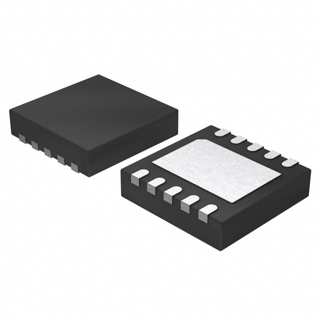
- Part No.:
- MCP73223-C2SI/MF
- Manufacturer:
- Microchip Technology
- Category:
- Battery Chargers
- Package:
- 10-VFDFN Exposed Pad
- Datasheet:
-
 MCP73223-C2SI/MF.pdf
- Description:
- IC BAT CNTL IRON PHOS 1-2C 10DFN
- Quantity:
- Payment:

- Shipping:

Inventory:2,201
Please send an inquiry. Send us your inquiry, and we will respond immediately.
Product details
Overview
MCP73223-C2SI/MF from Microchip Technology is a highly integrated linear lithium iron phosphate (LiFePO₄) battery charge management controller with integrated pass transistor, current sense, reverse discharge protection, and input overvoltage protection (OVP). It delivers 7.2V regulated charge voltage ±0.6% over –5°C to +55°C, supports 130–1100 mA resistor-programmable fast charge current, and operates across –40°C to +85°C ambient. It is designed for compact, cost-sensitive LiFePO₄ charging in power tools and backup energy storage.
For engineers reviewing the MCP73223-C2SI/MF datasheet, MCP73223-C2SI/MF pinout, MCP73223-C2SI/MF application, or MCP73223-C2SI/MF equivalent, key selection considerations include its 13V OVP threshold, factory-preset 7.2V charge voltage, 4V preconditioning threshold, 32-minute precondition timer, and DFN-10 (3 mm × 3 mm) thermal-pad package - all critical for safe, space-constrained LiFePO₄ charging designs.
Technical Context
The MCP73223-C2SI/MF implements a three-phase LiFePO₄-optimized charge algorithm: preconditioning (10% of IREG at VPTH = 4.0 V), constant-current fast charge (programmable 130–1100 mA), and constant-voltage regulation (7.20 V ±0.6%). It integrates thermal regulation (150°C shutdown with 10°C hysteresis) and automatic power-down when VDD falls within +50 mV of VBAT.
Its internal P-channel MOSFET pass transistor (RDS(ON) = 350 mΩ @ 105°C) enables direct linear regulation without external switching components. The PROG pin serves dual roles: programming fast charge current via 1–10 kΩ resistor and enabling/disabling charge via high-impedance (>200 kΩ) detection.
Key Specifications
| Parameter | Value and Actual Design Meaning |
|---|---|
| Charge Voltage | 7.20 V ±0.6% over –5°C to +55°C - ensures precise LiFePO₄ cell balancing and prevents overcharge degradation |
| OVP Threshold | 12.8–13.2 V - protects against AC adapter spikes and harsh input transients up to 18 V absolute max |
| Fast Charge Current | 130–1100 mA, set by 1–10 kΩ PROG-to-VSS resistor - enables flexible current scaling without redesign |
| Precondition Threshold | 4.0 V (factory preset) - initiates safe trickle charge for deeply depleted LiFePO₄ cells before fast charge |
| End-of-Charge Ratio | Selectable 5%, 7.5%, 10%, or 20% of IREG - balances full capacity recovery vs. cycle life extension |
| Operating Temp | –40°C to +85°C ambient - supports industrial and portable tool environments |
| Package | DFN-10 (3 mm × 3 mm) with exposed thermal pad - enables high-power dissipation in ultra-compact layouts |
Pinout & Package
Package: DFN-10 (3 mm × 3 mm) with exposed thermal pad (EP); EP must be connected to PCB ground plane via multiple vias for thermal performance.
| Pin/Terminal | Circuit Role | Design Meaning |
|---|---|---|
| VDD (Pins 1,2) | Battery management input supply | Accepts 4.2–13.0 V input; 18 V absolute max; powers internal circuitry and gate drive; requires ≥1 µF bypass to VSS |
| VBAT (Pins 3,4) | Battery charge control output | Drain of internal P-MOSFET; connects directly to LiFePO₄ battery positive; requires ≥1 µF bypass for stability |
| NC (Pins 5,6) | No connection | Unbonded pins; must remain unconnected on PCB |
| STAT (Pin 7) | Status output | Open-drain indicator; sinks up to 35 mA; used for LED status or microcontroller polling (Type 1: On/Off) |
| VSS (Pins 8,9) | Battery reference ground | Common return for battery negative, input supply negative, and bypass capacitors |
| PROG (Pin 10) | Current regulation & enable | Resistor-programmed fast charge current; floating or >200 kΩ disables charger; also functions as enable input |
| EP (Pin 11) | Exposed thermal pad | Must be soldered to PCB ground copper area with ≥4 thermal vias to maintain TJ ≤ 125°C under full load |
Key Features
| Feature | Design Value |
|---|---|
| Integrated pass transistor | 350 mΩ RDS(ON) @ 105°C eliminates need for external MOSFET and reduces BOM count |
| Input overvoltage protection | 13 V OVP threshold with 150 mV hysteresis prevents damage from low-cost AC adapters and plug-in spikes |
| Factory-preset LiFePO₄ algorithm | 7.2 V regulation, 4.0 V precondition threshold, 32-min precondition timer - removes firmware dependency and simplifies certification |
| Reverse discharge protection | Blocks battery-to-input current flow during standby - eliminates need for external blocking diode |
| Thermal regulation & shutdown | Continuous current reduction above ~110°C and hard shutdown at 150°C with 10°C hysteresis - ensures reliability in enclosed enclosures |
Applications
| Power Tools | Backup Energy Storage |
|---|---|
Use Scenario: Cordless drills, impact drivers, and saws using 2-cell (7.2 V) LiFePO₄ packs requiring rapid, safe recharge between shifts. IC Role / Device Role / Timing Role: Primary linear charge controller managing full CC/CV profile, OVP, thermal foldback, and end-of-charge termination. Use Value: Enables compact, fanless charger design with no external MOSFET or sense resistor - reducing bill-of-materials and board area by >30%. | Use Scenario: Uninterruptible power supplies (UPS) and solar home systems storing energy in 2S LiFePO₄ batteries for off-grid lighting or telecom backup. IC Role / Device Role / Timing Role: Standalone charge manager providing automatic recharge at 95% VREG, deep-discharge preconditioning, and safety timers. Use Value: Guarantees long-term cycle life (>2000 cycles) through precise 7.20 V ±0.6% regulation and avoids premature failure from overvoltage or thermal stress. |
| Toys | Low-Cost LiFePO₄ Chargers |
Use Scenario: Ride-on electric toys and RC vehicles using sealed 2S LiFePO₄ batteries charged via wall adapters with variable output quality. IC Role / Device Role / Timing Role: Robust charge supervisor handling input ripple, voltage spikes, and intermittent loads during charging. Use Value: Built-in 18 V absolute max rating and 13 V OVP prevent field failures from low-cost AC-DC adapters - improving product return rate. | Use Scenario: OEM battery chargers for medical devices, portable instrumentation, and IoT sensors where size, cost, and safety certification are critical. IC Role / Device Role / Timing Role: Fully integrated charge IC eliminating discrete regulators, comparators, and timers required in legacy designs. Use Value: Reduces design time by >6 weeks versus discrete solutions and meets IEC 62368-1 requirements out-of-the-box with no additional safety components. |
Equivalent & Alternatives
The following parts are listed as comparable options for similar LiFePO₄ battery charge management applications.
| Alternative Part | Technical Difference | Application Difference | Selection Advice |
|---|---|---|---|
| MCP73223-C2A/MF | Same 7.2 V charge voltage, 13 V OVP, and 4 V precondition threshold, but automatic recharge disabled (0% VRTH/VREG) | Suitable for applications requiring single-charge-only behavior (e.g., disposable medical devices) | Select when battery must not self-recharge after partial discharge - avoids unintended cycling in storage |
| BQ25611DRTWR | Switch-mode buck charger (not linear); supports 7.2–8.4 V output; requires external inductor and MOSFETs; higher efficiency but larger solution size | Preferred for >1 A applications or thermally constrained designs where >85% efficiency is mandatory | Choose only if thermal budget prohibits linear operation - adds complexity but improves runtime per charge |
Compared with MCP73223-C2A/MF, the MCP73223-C2SI/MF provides automatic recharge at 95% VREG, enhancing usability in consumer tools; compared with BQ25611DRTWR, it offers smaller footprint and lower EMI but trades off efficiency for simplicity in sub-1 A applications.
Availability
MCP73223-C2SI/MF is available at Aetrix Electronics and suitable for power tools, backup energy storage, and toy applications requiring stable component supply, long-lifecycle support, and RoHS-compliant packaging.
Supply support for MCP73223-C2SI/MF includes scheduled delivery planning, volume procurement assistance, BOM continuity management, traceable sourcing, and lifecycle availability coordination for OEM customers, industrial embedded developers, connected-device designers, and electronics production programs.
Manufacturer
Microchip Technology Inc. is a leading provider of microcontrollers, analog, FPGA, and mixed-signal semiconductors, headquartered in Chandler, Arizona, with global design and manufacturing operations.
The MCP73xx family is specifically engineered for cost-sensitive, space-constrained LiFePO₄ battery charging - delivering factory-tuned algorithms, integrated protection, and DFN packaging to eliminate external components and accelerate time-to-market.
FAQ
What is the exact charge voltage and tolerance of the MCP73223-C2SI/MF?
The MCP73223-C2SI/MF provides a factory-preset regulated charge voltage of 7.20 V with a tolerance of ±0.6% over the temperature range of –5°C to +55°C. This value is specified in the Electrical Characteristics table (DS22191E, page 4) and ensures optimal LiFePO₄ cell health and capacity retention without requiring external voltage-setting components.
Does the MCP73223-C2SI/MF support automatic recharge, and at what threshold?
Yes, the MCP73223-C2SI/MF supports automatic recharge at a factory-set threshold of 95% of VREG (i.e., 6.84 V for 7.20 V nominal). When battery voltage drops below this level in Charge Complete mode, the device initiates a new charge cycle. This behavior is confirmed in Table 2 (Standard Sample Options) and Section 5.8 of the datasheet.
What is the function of the PROG pin on the MCP73223-C2SI/MF?
The PROG pin on the MCP73223-C2SI/MF serves two critical functions: (1) it sets the fast charge current via an external resistor (1–10 kΩ to VSS), yielding 130–1100 mA; and (2) it acts as an enable/disable input - floating or connecting to >200 kΩ places the MCP73223-C2SI/MF in shutdown mode. Both roles are documented in Section 3.6 and Figure 4-1 of DS22191E.
What package type and thermal requirements apply to the MCP73223-C2SI/MF?
The MCP73223-C2SI/MF uses a DFN-10 (3 mm × 3 mm) package with an exposed thermal pad (EP). The EP must be soldered to a PCB ground plane with ≥4 thermal vias to achieve θJA = 64°C/W. This is essential to maintain junction temperature ≤125°C under maximum load, as specified in the Thermal Package Resistances table (DS22191E, page 6).
How does the MCP73223-C2SI/MF handle overvoltage and thermal faults?
The MCP73223-C2SI/MF responds to overvoltage by entering shutdown mode when VDD exceeds 13.2 V (OVP start), with 150 mV hysteresis. For thermal faults, it begins current foldback above ~110°C and triggers hard shutdown at 150°C (TSD), resuming only after die cools by ~10°C. Both protections are active simultaneously and are verified in Sections 5.2, 5.9, and 5.10 of DS22191E.
MCP73223-C2SI/MF Specifications
- Product attributes
- Attribute value
- Manufacturer:
- Microchip Technology
- Series:
- -
- Package/Case:
- 10-VFDFN Exposed Pad
- Packaging:
- Tube
- Product Status:
- Active
- Battery Chemistry:
- Lithium Iron Phosphate
- Number of Cells:
- 1 ~ 2
- Current - Charging:
- Constant - Programmable
- Programmable Features:
- Current, Timer
- Fault Protection:
- Over Temperature, Over Voltage, Reverse Current
- Charge Current - Max:
- 1.1A
- Battery Pack Voltage:
- 7.2V
- Voltage - Supply (Max):
- 16V
- Interface:
- -
- Operating Temperature:
- -40°C ~ 85°C (TA)
- Grade:
- -
- Qualification:
- -
- Mounting Type:
- Surface Mount
- Supplier Device Package:
- 10-DFN (3x3)
MCP73223-C2SI/MF FAQ
1.How can I place an order for MCP73223-C2SI/MF through Aetrix?
Please submit a Request for Quotation (RFQ) for MCP73223-C2SI/MF on Aetrix. Our sales agent will provide a competitive quotation and guide you through the order confirmation once you accept the terms.
2.Are the price and stock information for MCP73223-C2SI/MF reliable?
The price and inventory of MCP73223-C2SI/MF are updated periodically and may fluctuate due to market conditions. Stock and pricing data are typically refreshed every 24 hours. Quotation validity for MCP73223-C2SI/MF is usually 5 days.
3.What payment methods are accepted for MCP73223-C2SI/MF?
We accept Wire Transfer, PayPal, Credit Card, Western Union, MoneyGram, and Escrow for MCP73223-C2SI/MF transactions.
Note: Certain payment methods may incur a processing fee.
4.How is shipping managed for MCP73223-C2SI/MF?
MCP73223-C2SI/MF orders can be shipped via leading logistics carriers, including DHL, UPS, FedEx, TNT, or Registered Mail.
Once your MCP73223-C2SI/MF order is processed, you will receive an email with the shipment details and tracking number.
Note: Tracking information may take up to 24 hours to appear. Express delivery typically takes 3–5 business days.
5.How can I obtain technical support or documentation for MCP73223-C2SI/MF?
For technical support, including MCP73223-C2SI/MF datasheets, pinout diagrams, or application guidance, please contact our engineering support team. They can provide detailed documentation and assistance for your MCP73223-C2SI/MF requirements.
6.How does Aetrix verify that MCP73223-C2SI/MF is sourced from the original manufacturer or authorized distributors?
All MCP73223-C2SI/MF products on Aetrix are procured from qualified distributors and authorized channels. Our dedicated quality assurance team conducts strict verification, including traceability checks and, if necessary, third-party testing. This ensures that MCP73223-C2SI/MF meets industry standards.
7.What is the process for return or replacement of MCP73223-C2SI/MF?
All MCP73223-C2SI/MF units undergo pre-shipment inspection (PSI). If there is an issue with MCP73223-C2SI/MF, returns or replacements are accepted under the following conditions:
1.Quantity discrepancies, incorrect items, or visible external defects (such as breakage or corrosion), acknowledged by Aetrix.
2.The issue is reported within 90 days of delivery.
3.The MCP73223-C2SI/MF part is unused and in its original packaging.
Return procedure for MCP73223-C2SI/MF:
1.Submit a request within 90 days.
2.Obtain a Return Material Authorization (RMA) from Aetrix.
MCP73223-C2SI/MF Tags

-
BQ21040DBVR
Texas Instruments

-
MCP73812T-420I/OT
Microchip Technology
-
MCP73831T-2ACI/OT
Microchip Technology
-
MCP73832T-2ACI/OT
Microchip Technology
-
MCP73831T-2DCI/OT
Microchip Technology
-
MCP73832T-2DCI/OT
Microchip Technology
-
MCP73831T-2ATI/OT
Microchip Technology
-
MCP73832T-2ATI/OT
Microchip Technology
-
MCP73831T-5ACI/OT
Microchip Technology

-
MCP73832T-2ACI/MC
Microchip Technology
-
MCP73831T-2ACI/MC
Microchip Technology
-
MCP73831T-2ATI/MC
Microchip Technology
Tech Hub

TTL and CMOS logic families differ in thresholds, loading, output drive, power and timing. This engineering guide compares 74HC and 74HCT, calculates noise margins and checks 3.3 V/5 V compatibility.

A practical engineering guide to 3.3V and 5V logic compatibility, input thresholds, resistor dividers, translator ICs, MOSFET level shifting, I2C pull-ups, timing limits and power-sequencing risks.

The 74HC595 uses push-pull logic outputs, while the TPIC6B595 uses 50 V open-drain DMOS sinks for higher-power loads. This guide compares timing, current limits, 3.3 V interfacing, load wiring, thermal…

The 74HC595 converts serial data into eight stable parallel outputs. This guide covers pin functions, shift and storage timing, OE and MR behavior, drive-current limits, cascading, voltage compatibilit…

A technical comparison of level-sensitive latches and edge-triggered flip-flops, covering timing windows, setup and hold limits, master–slave operation, time borrowing, race-through, HDL inference and…

A D latch stores one bit while Enable controls when data can pass. This reference covers gate-level operation, truth tables, transparency, setup and hold timing, LE versus OE, common ICs and practical …

An SR latch stores one bit through cross-coupled feedback. This engineering reference covers NOR and NAND implementations, truth tables, forbidden-state recovery, gated operation, switch debouncing, fa…

Latch circuits retain one bit through feedback. This technical reference covers SR and D latches, truth tables, transparency, timing limits, latch-versus-flip-flop behavior, applications and common log…

An engineering guide to LED driver operation, constant-current and constant-voltage outputs, linear and switching topologies, dimming, IC selection, calculations, replacement compatibility, and fault c…

Operational amplifier guide covering op amp basics, feedback, ideal vs real op amps, common configurations, buffer circuits, offset, bias current, gain-bandwidth, slew rate, rail-to-rail limits and sel…


