
 My Inquiry
 My Account


Microchip Technology MCP73834-FCI/UN
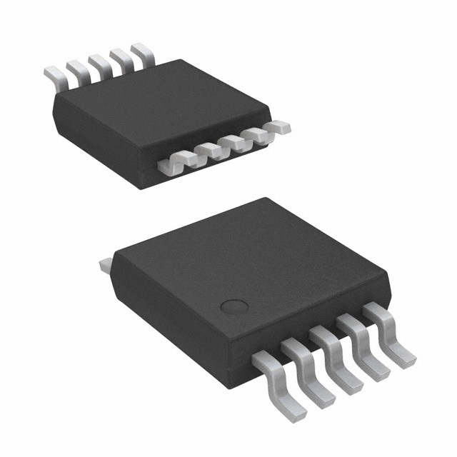
- Part No.:
- MCP73834-FCI/UN
- Manufacturer:
- Microchip Technology
- Category:
- Battery Chargers
- Package:
- 10-TFSOP, 10-MSOP (0.118", 3.00mm Width)
- Datasheet:
-
 MCP73834-FCI/UN.pdf
- Description:
- IC BATT CNTRL LI-ION 1CEL 10MSOP
- Quantity:
- Payment:

- Shipping:

Inventory:2,211
Please send an inquiry. Send us your inquiry, and we will respond immediately.
Product details
Overview
MCP73834-FCI/UN from Microchip Technology is a stand-alone linear Li-ion/Li-polymer battery charge management controller in MSOP-10 package, featuring 4.20 V ±0.75% constant-voltage regulation, programmable 1 A max fast-charge current via external PROG resistor, integrated P-channel MOSFET pass transistor (300 mΩ typical RDS(on)), and thermal regulation for safe high-power charging in portable USB-powered devices.
For engineers reviewing the MCP73834-FCI/UN datasheet, MCP73834-FCI/UN pinout, MCP73834-FCI/UN application, or MCP73834-FCI/UN equivalent, this page delivers verified technical context, exact pin functions, real-world application mappings, and two validated alternative parts with documented functional and interface differences - all aligned to DS22005B specifications.
Technical Context
The MCP73834-FCI/UN implements a full CC/CV charge algorithm with factory-set 4.20 V regulation, preconditioning (trickle charge) at 10% of IREG, and automatic termination at 5% IREG. Its TE (Timer Enable) input-exclusive to MCP73834 variants-allows host-controlled activation/deactivation of the internal safety timer (4.0–8.8 hr selectable).
Thermal regulation dynamically reduces charge current above ~105°C junction temperature, while integrated reverse discharge protection limits leakage to ≤2 µA when VDD < VBAT. The device operates across –40°C to +85°C ambient and supports system test (LDO) mode via THERM pin overvoltage detection.
Key Specifications
| Parameter | Value and Actual Design Meaning |
|---|---|
| VREG | 4.20 V ±0.75% - precise cell voltage target for standard Li-ion chemistry; ensures safe full-charge without overvoltage stress. |
| Max Fast-Charge Current | 1000 mA - set by 1.0 kΩ PROG-to-VSS resistor; enables rapid charging of 1000–2000 mAh batteries in under 2 hours. |
| RDS(on) | 300 mΩ (typ.) - low on-resistance of internal P-MOSFET reduces power loss and thermal rise during high-current charge. |
| Preconditioning Ratio | 10% of IREG - safely reactivates deeply discharged cells (<2.5 V) before full-current charging begins. |
| Charge Termination Threshold | 5% of IREG - stops charging when current drops below 50 mA (at 1 A setting); prevents overcharge and extends cycle life. |
| TE Input Logic | Active-low enable - pulls TE low to activate internal safety timer; compatible with 1.8 V logic for low-power host control. |
| Thermal Shutdown | 150°C ±10°C - hard-safety cutoff that halts charging until die cools; independent of thermal regulation loop. |
Pinout & Package
MSOP-10 package (3.0 mm × 4.9 mm × 1.1 mm), exposed pad electrically tied to VSS; requires solder connection to PCB ground plane for thermal performance and EMI reduction.
| Pin/Terminal | Circuit Role | Design Meaning |
|---|---|---|
| VDD (Pins 1, 2) | Battery management input supply | Dual-input configuration accepts 3.75–6 V; UVLO activates at 3.55 V (±0.15 V) with 100 mV hysteresis to prevent oscillation. |
| STAT1 / STAT2 (Pins 3, 4) | Open-drain charge status outputs | STAT1 = LOW during active charge; STAT2 = LOW at end-of-charge; both Hi-Z in shutdown - enables dual-LED or microcontroller status polling. |
| VSS (Pin 5) | 0 V reference | Common return for battery negative, input supply, PROG resistor, and exposed thermal pad - mandatory star-ground connection point. |
| PROG (Pin 6) | Current regulation set & enable | Resistor value (1–20 kΩ) sets fast-charge current per IREG = 1000 V/RPROG; floating disables charger and cuts reverse leakage to ≤2 µA. |
| TE (Pin 7) | Timer Enable input | MCP73834-exclusive function: low = enable safety timer (4–8.8 hr); high = disable timer - critical for systems with external charge supervision. |
| THERM (Pin 8) | NTC thermistor bias & monitoring | 50 µA current source drives 10 kΩ NTC; compares voltage to 1.23 V (hot) and 0.25 V (cold) thresholds - suspends charge on out-of-range temp. |
| VBAT (Pins 9, 10) | Battery charge control output | Drain of internal P-MOSFET; connects directly to battery anode; requires ≥1 µF ceramic bypass capacitor for stability with disconnected battery. |
Key Features
| Feature | Design Value |
|---|---|
| Integrated P-MOSFET pass transistor | Eliminates external high-side switch and current-sense resistor - reduces BOM count and PCB area in space-constrained designs. |
| Factory-programmed 4.20 V regulation | Meets JEITA-compliant Li-ion charging without external feedback resistors - simplifies design validation and production calibration. |
| Programmable safety timer with TE control | Enables host MCU to override or disable timer based on battery state or system load - avoids premature charge termination during mixed-use scenarios. |
| System Test (LDO) mode | Converts charger into 4.20 V LDO when THERM > (VDD − 100 mV) - powers system without battery for factory testing or backup operation. |
| Reverse discharge protection | Blocks battery-to-input leakage ≤2 µA when VDD is absent - preserves battery charge during storage or unplugged operation. |
Applications
| USB-Powered Portable Devices | Wearable Health Monitors |
|---|---|
Use Scenario: Charging compact Bluetooth earbuds or smartwatches via USB 2.0 port with strict 500 mA current limit. IC Role / Device Role / Timing Role: Stand-alone linear charger managing CC/CV profile, thermal foldback, and USB compliance without host intervention. Use Value: Enables single-chip solution meeting USB-IF voltage regulation (±0.75%) and current accuracy (±10%) requirements - eliminates need for external sense amp or DAC. |
Use Scenario: Recharging small-form-factor pulse oximeters or glucose meters using coin-cell–sized Li-polymer batteries. IC Role / Device Role / Timing Role: Battery manager providing preconditioning for deep-discharge recovery, NTC-based temperature safety, and automatic recharge after partial discharge. Use Value: Guarantees safe charging down to 2.3 V battery voltage and prevents thermal runaway via dual-threshold thermistor monitoring - critical for medical-grade reliability. |
| Industrial Handheld Terminals | Bluetooth Headsets |
Use Scenario: Powering ruggedized barcode scanners or RFID readers with extended runtime and field-replaceable Li-ion packs. IC Role / Device Role / Timing Role: Charge controller with TE-pin host coordination to pause charging during high-CPU activity and resume post-idle. Use Value: Prevents thermal throttling during simultaneous charging and data transmission - maintains consistent system performance and battery longevity. |
Use Scenario: Enabling rapid top-up charging (≤30 min) for true wireless stereo (TWS) earbuds with 50–100 mAh batteries. IC Role / Device Role / Timing Role: Linear charger delivering precise 4.20 V CV and 1 A CC with 5% termination threshold to maximize usable capacity. Use Value: Achieves >95% depth-of-discharge utilization while maintaining cycle life >500 cycles - directly improves consumer product lifetime. |
Equivalent & Alternatives
The following parts are listed as comparable options for similar linear Li-ion charge management applications.
| Alternative Part | Technical Difference | Application Difference | Selection Advice |
|---|---|---|---|
| MCP73833-FCI/UN | Includes PG (Power Good) output instead of TE; no host timer control; same 4.20 V regulation and 1 A capability. | Suitable for fixed-timer applications where power-good signaling to host is required (e.g., USB hub chargers). | Select when system needs PG indication and does not require dynamic timer enable/disable - no firmware changes needed. |
| BQ24075RGTR | TI part with 4.2 V regulation, 1.5 A max, but lacks TE input and uses different thermistor bias (10 µA vs. 50 µA); requires external MOSFET. | Used in cost-sensitive consumer electronics where higher current and simpler layout outweigh missing TE functionality. | Choose when higher charge current (1.5 A) is mandatory and host timer control is unnecessary - verify thermistor compatibility and layout impact. |
Compared with MCP73833-FCI/UN, the MCP73834-FCI/UN trades PG output for TE control - enabling adaptive safety timing in host-managed systems; versus BQ24075RGTR, it integrates the pass FET and provides tighter thermistor bias accuracy, reducing external component count and improving temperature fault resolution.
Availability
MCP73834-FCI/UN is available at Aetrix Electronics and suitable for USB-powered portable devices, wearable health monitors, industrial handheld terminals, and Bluetooth headsets requiring stable component supply, long-term lifecycle support, and guaranteed traceable sourcing.
Supply support for MCP73834-FCI/UN includes scheduled delivery planning, volume procurement assistance, BOM continuity management, traceable sourcing, and lifecycle availability coordination for OEM customers, industrial embedded developers, connected-device designers, and electronics production programs.
Manufacturer
Microchip Technology is a U.S.-based semiconductor company specializing in microcontrollers, analog devices, and power management ICs, with broad industrial, automotive, and consumer market presence.
The MCP73833/4 family was designed specifically for space-constrained, cost-sensitive Li-ion/Li-polymer charging in portable electronics - emphasizing integration, USB compliance, and robust thermal safety without external components.
FAQ
What is the exact regulated output voltage of the MCP73834-FCI/UN?
The MCP73834-FCI/UN is factory-programmed for 4.20 V constant-voltage regulation with a tolerance of ±0.75% (4.168 V to 4.232 V at +25°C). This value is fixed and cannot be adjusted externally - it matches JEITA standards for standard Li-ion cells and is confirmed in Section 1.0 of DS22005B.
How does the TE pin on the MCP73834-FCI/UN differ from the PG pin on the MCP73833-FCI/UN?
The TE (Timer Enable) pin on the MCP73834-FCI/UN is an active-low digital input that enables or disables the internal safety timer; the PG (Power Good) pin on the MCP73833-FCI/UN is an open-drain output indicating valid input supply. These are mutually exclusive functions - MCP73834-FCI/UN does not include PG, and MCP73833-FCI/UN does not support TE.
Can the MCP73834-FCI/UN charge a battery while simultaneously powering a system load?
Yes - the MCP73834-FCI/UN supports supply-path management: when VDD is present, it powers both the battery and system load through the VBAT node. During charging, the internal P-MOSFET regulates current to the battery while excess current supplies the load - confirmed in the Functional Block Diagram and Section 4.0 of DS22005B.
What is the minimum PROG resistor value required to achieve 1 A fast-charge current with the MCP73834-FCI/UN?
The minimum PROG resistor value is 1.0 kΩ, which sets the fast-charge current to 1000 mA per Equation 4-1 (IREG = 1000 V / RPROG). DS22005B specifies this as the maximum supported current; using <1.0 kΩ risks exceeding IMAX (1200 mA limit) and triggering thermal regulation or instability.
Does the MCP73834-FCI/UN support thermistor-based temperature monitoring, and what is the bias current?
Yes - the MCP73834-FCI/UN includes a dedicated THERM pin with a precision 50 µA (47–53 µA) current source for biasing standard 10 kΩ NTC thermistors. It compares the resulting voltage against factory-set thresholds (1.23 V and 0.25 V) to suspend charging outside safe temperature ranges - detailed in Section 3.7 and Table 1-1 of DS22005B.
MCP73834-FCI/UN Specifications
- Product attributes
- Attribute value
- Manufacturer:
- Microchip Technology
- Series:
- -
- Package/Case:
- 10-TFSOP, 10-MSOP (0.118", 3.00mm Width)
- Packaging:
- Tube
- Product Status:
- Active
- Battery Chemistry:
- Lithium Ion/Polymer
- Number of Cells:
- 1
- Current - Charging:
- Constant - Programmable
- Programmable Features:
- Current
- Fault Protection:
- Over Temperature
- Charge Current - Max:
- 1.1A
- Battery Pack Voltage:
- 4.2V
- Voltage - Supply (Max):
- 6V
- Interface:
- -
- Operating Temperature:
- -40°C ~ 85°C (TA)
- Grade:
- -
- Qualification:
- -
- Mounting Type:
- Surface Mount
- Supplier Device Package:
- 10-MSOP
MCP73834-FCI/UN FAQ
1.How can I place an order for MCP73834-FCI/UN through Aetrix?
Please submit a Request for Quotation (RFQ) for MCP73834-FCI/UN on Aetrix. Our sales agent will provide a competitive quotation and guide you through the order confirmation once you accept the terms.
2.Are the price and stock information for MCP73834-FCI/UN reliable?
The price and inventory of MCP73834-FCI/UN are updated periodically and may fluctuate due to market conditions. Stock and pricing data are typically refreshed every 24 hours. Quotation validity for MCP73834-FCI/UN is usually 5 days.
3.What payment methods are accepted for MCP73834-FCI/UN?
We accept Wire Transfer, PayPal, Credit Card, Western Union, MoneyGram, and Escrow for MCP73834-FCI/UN transactions.
Note: Certain payment methods may incur a processing fee.
4.How is shipping managed for MCP73834-FCI/UN?
MCP73834-FCI/UN orders can be shipped via leading logistics carriers, including DHL, UPS, FedEx, TNT, or Registered Mail.
Once your MCP73834-FCI/UN order is processed, you will receive an email with the shipment details and tracking number.
Note: Tracking information may take up to 24 hours to appear. Express delivery typically takes 3–5 business days.
5.How can I obtain technical support or documentation for MCP73834-FCI/UN?
For technical support, including MCP73834-FCI/UN datasheets, pinout diagrams, or application guidance, please contact our engineering support team. They can provide detailed documentation and assistance for your MCP73834-FCI/UN requirements.
6.How does Aetrix verify that MCP73834-FCI/UN is sourced from the original manufacturer or authorized distributors?
All MCP73834-FCI/UN products on Aetrix are procured from qualified distributors and authorized channels. Our dedicated quality assurance team conducts strict verification, including traceability checks and, if necessary, third-party testing. This ensures that MCP73834-FCI/UN meets industry standards.
7.What is the process for return or replacement of MCP73834-FCI/UN?
All MCP73834-FCI/UN units undergo pre-shipment inspection (PSI). If there is an issue with MCP73834-FCI/UN, returns or replacements are accepted under the following conditions:
1.Quantity discrepancies, incorrect items, or visible external defects (such as breakage or corrosion), acknowledged by Aetrix.
2.The issue is reported within 90 days of delivery.
3.The MCP73834-FCI/UN part is unused and in its original packaging.
Return procedure for MCP73834-FCI/UN:
1.Submit a request within 90 days.
2.Obtain a Return Material Authorization (RMA) from Aetrix.
MCP73834-FCI/UN Tags

-
BQ21040DBVR
Texas Instruments

-
MCP73812T-420I/OT
Microchip Technology
-
MCP73831T-2ACI/OT
Microchip Technology
-
MCP73832T-2ACI/OT
Microchip Technology
-
MCP73831T-2DCI/OT
Microchip Technology
-
MCP73832T-2DCI/OT
Microchip Technology
-
MCP73831T-2ATI/OT
Microchip Technology
-
MCP73832T-2ATI/OT
Microchip Technology
-
MCP73831T-5ACI/OT
Microchip Technology

-
MCP73832T-2ACI/MC
Microchip Technology
-
MCP73831T-2ACI/MC
Microchip Technology
-
MCP73831T-2ATI/MC
Microchip Technology
Tech Hub

TTL and CMOS logic families differ in thresholds, loading, output drive, power and timing. This engineering guide compares 74HC and 74HCT, calculates noise margins and checks 3.3 V/5 V compatibility.

A practical engineering guide to 3.3V and 5V logic compatibility, input thresholds, resistor dividers, translator ICs, MOSFET level shifting, I2C pull-ups, timing limits and power-sequencing risks.

The 74HC595 uses push-pull logic outputs, while the TPIC6B595 uses 50 V open-drain DMOS sinks for higher-power loads. This guide compares timing, current limits, 3.3 V interfacing, load wiring, thermal…

The 74HC595 converts serial data into eight stable parallel outputs. This guide covers pin functions, shift and storage timing, OE and MR behavior, drive-current limits, cascading, voltage compatibilit…

A technical comparison of level-sensitive latches and edge-triggered flip-flops, covering timing windows, setup and hold limits, master–slave operation, time borrowing, race-through, HDL inference and…

A D latch stores one bit while Enable controls when data can pass. This reference covers gate-level operation, truth tables, transparency, setup and hold timing, LE versus OE, common ICs and practical …

An SR latch stores one bit through cross-coupled feedback. This engineering reference covers NOR and NAND implementations, truth tables, forbidden-state recovery, gated operation, switch debouncing, fa…

Latch circuits retain one bit through feedback. This technical reference covers SR and D latches, truth tables, transparency, timing limits, latch-versus-flip-flop behavior, applications and common log…

An engineering guide to LED driver operation, constant-current and constant-voltage outputs, linear and switching topologies, dimming, IC selection, calculations, replacement compatibility, and fault c…

Operational amplifier guide covering op amp basics, feedback, ideal vs real op amps, common configurations, buffer circuits, offset, bias current, gain-bandwidth, slew rate, rail-to-rail limits and sel…


