
 My Inquiry
 My Account


Monolithic Power Systems Inc. MCS1802GS-20-Z
.jpg)
- Part No.:
- MCS1802GS-20-Z
- Manufacturer:
- Monolithic Power Systems Inc.
- Category:
- Current Sensors
- Package:
- 8-SOIC (0.154", 3.90mm Width)
- Datasheet:
-
 MCS1802GS-20-Z.pdf
- Description:
- 3.3V, LINEAR HALL-EFFECT CURRENT
- Quantity:
- Payment:

- Shipping:

Inventory:1,142
Please send an inquiry. Send us your inquiry, and we will respond immediately.
Product details
Overview
MCS1802GS-20-Z from Monolithic Power Systems is a 3.3V linear Hall-effect current sensor with galvanic isolation, ±20A bidirectional sensing range, ±2.5% total output error over temperature (−40°C to +125°C), 66 mV/A sensitivity, and 0.9 mΩ internal conductor resistance. It replaces opto-isolators in motor control and power supply current monitoring where high accuracy, magnetic immunity, and compact SOIC-8 packaging are required.
For engineers reviewing the MCS1802GS-20-Z datasheet, MCS1802GS-20-Z pinout, MCS1802GS-20-Z application, or MCS1802GS-20-Z equivalent, key selection criteria include its differential Hall architecture for stray-field rejection, 2.2 kVRMS isolation rating, adjustable bandwidth up to 100 kHz via external FILT capacitor, ratiometric analog output, and factory-trimmed offset and sensitivity.
Technical Context
The MCS1802GS-20-Z uses a differential Hall array with spinning current offset cancellation to achieve stable zero-current output (VOUT(Q) = VCC/2) and low thermal drift. Its primary conductor path (IP+, IP−) is galvanically isolated from signal pins (VCC, VOUT, FILT, GND), enabling safe high-side current sensing without shunt resistors or external isolation.
Bandwidth is programmable via an external capacitor on the FILT pin, interacting with internal 1.5 kΩ resistance and 1 nF capacitance; unconnected FILT yields 100 kHz bandwidth. The device features 4 µs output rising time, 1.5 µs propagation delay, and operates across −40°C to +125°C junction temperature with 3.0–3.6 V supply.
Key Specifications
| Parameter | Value and Actual Design Meaning |
|---|---|
| Supply Voltage | 3.3 V nominal; operates from 3.0 V to 3.6 V - ensures compatibility with standard logic rails and low-noise LDOs. |
| Current Range | ±20 A bidirectional - supports precise measurement of charging/discharging, forward/reverse motor currents. |
| Sensitivity | 66 mV/A at 25°C - delivers 1.32 V full-scale output swing (±20 A × 66 mV/A) centered at VCC/2 = 1.65 V. |
| Total Output Error | ±2.5% over −40°C to +125°C - guarantees accuracy without system-level calibration across automotive and industrial ambient conditions. |
| Isolation Voltage | 2.2 kVRMS - certified per IEC 62368-1, enabling replacement of optocouplers in safety-critical AC/DC power stages. |
| Conductor Resistance | 0.9 mΩ - minimizes power loss (≤360 mW at ±20 A) and self-heating in high-current paths. |
| Rising Time | 4 µs - supports real-time overcurrent fault detection in switch-mode power supplies and motor drives. |
| Operating Temperature | −40°C to +125°C - qualified for under-hood automotive, industrial inverters, and server PSU applications. |
Pinout & Package
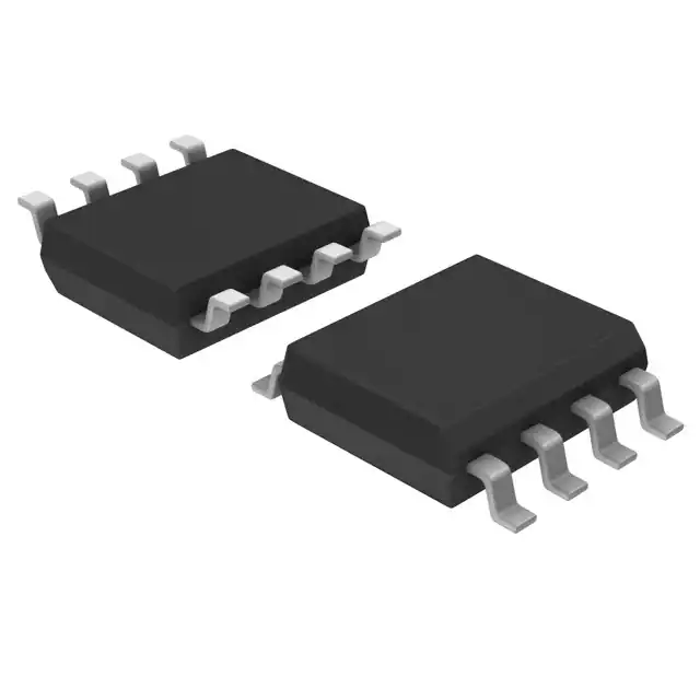
Package: SOIC-8 (5 mm × 4 mm), surface-mount, with primary current terminals (IP+, IP−) physically separated from signal pins to maintain 4.2 mm creepage and clearance for reinforced isolation.
| Pin/Terminal | Circuit Role | Design Meaning |
|---|---|---|
| 1, 2 IP+ | Primary current input (+) | Internally shorted high-current input node; connects to positive side of load or bus bar - carries up to ±20 A with minimal voltage drop. |
| 3, 4 IP− | Primary current return (−) | Internally shorted high-current return node; completes current path through integrated conductor - enables true bidirectional sensing. |
| 5 GND | Signal ground reference | Analog ground for VOUT and internal circuitry; must be star-connected to minimize noise coupling into sensitive Hall front-end. |
| 6 FILT | Bandwidth filter terminal | Connects to external capacitor (CF) to set 3dB bandwidth; floating for maximum 100 kHz response - critical for EMI filtering and transient suppression. |
| 7 VOUT | Analog output voltage | Ratiometric, single-ended voltage proportional to IP (±20 A → ±1.32 V around 1.65 V); drives ≥4.7 kΩ loads with <10 nF capacitance. |
| 8 VCC | 3.3 V supply input | Power rail for Hall sensors and signal chain; requires local 1 µF low-ESR ceramic bypass capacitor placed adjacent to pin. |
Key Features
| Feature | Design Value |
|---|---|
| Differential Hall sensing | Rejects uniform external magnetic fields (e.g., nearby inductors/motors) by measuring field gradient - eliminates need for magnetic shielding. |
| Galvanic isolation | 2.2 kVRMS withstand voltage between IP and signal pins - enables direct high-voltage bus monitoring without external isolators. |
| Factory-trimmed accuracy | ±2.5% total output error over full temperature range - reduces BOM count and calibration effort in production test. |
| Adjustable bandwidth | Configurable from ~10 kHz to 100 kHz using external CF capacitor - balances noise rejection vs. response speed for specific application needs. |
| Low-conductor resistance | 0.9 mΩ primary path - limits power dissipation to ≤360 mW at ±20 A, avoiding thermal derating in compact PCB layouts. |
| Ratiometric output | VOUT scales with VCC variations - maintains measurement integrity when supply rails fluctuate due to load transients or LDO tolerance. |
Applications
| Motor Control | Automotive Systems |
|---|---|
Use Scenario: Real-time phase current sensing in 3-phase BLDC motor drivers for e-bikes and power tools. IC Role / Device Role / Timing Role: Isolated analog current feedback for FOC (field-oriented control) algorithms, with 4 µs rising time enabling cycle-by-cycle overcurrent protection. Use Value: Eliminates shunt resistor heat and layout complexity while maintaining ±2.5% accuracy across −40°C to +125°C ambient - critical for torque consistency and thermal management. | Use Scenario: Battery pack current monitoring in 12 V/48 V mild-hybrid vehicles for state-of-charge and fault detection. IC Role / Device Role / Timing Role: Bidirectional DC current sensor on high-side battery feed, interfacing directly with MCU ADC with ratiometric scaling. Use Value: 2.2 kVRMS isolation meets automotive functional safety requirements (ISO 26262 ASIL-B ready), and 0.9 mΩ resistance avoids measurable voltage drop in high-current discharge paths. |
| Switch-Mode Power Supplies | Over-Current Fault Protection |
Use Scenario: Primary-side current sensing in isolated flyback or LLC resonant converters for digital power management. IC Role / Device Role / Timing Role: High-bandwidth (100 kHz) analog current monitor replacing optocoupler-based feedback - enables adaptive peak-current-mode control. Use Value: Differential Hall architecture rejects transformer leakage field interference, improving regulation stability and reducing output ripple under dynamic load steps. | Use Scenario: Fast-acting overcurrent detection in industrial PLC output modules driving solenoids and contactors. IC Role / Device Role / Timing Role: Analog current threshold comparator input with sub-5 µs response - triggers hardware shutdown before MOSFET failure. Use Value: 1.5 µs propagation delay and 4 µs rise time enable detection of 10 µs current spikes, preventing catastrophic short-circuit damage in 24 V DC control systems. |
Equivalent & Alternatives
The following parts are listed as comparable options for similar linear Hall-effect current sensing applications.
| Alternative Part | Technical Difference | Application Difference | Selection Advice |
|---|---|---|---|
| ACS724LLCTR-20AB-T | 5 V supply; ±20 A range; 100 mV/A sensitivity; 2.4 kVRMS isolation; SOIC-8 package. | Requires 5 V rail and delivers higher output swing (±2 V), but lacks ratiometric output and has wider offset drift (±20 mV). | Select if 5 V system integration is mandatory and higher output SNR is needed; verify VCC compatibility and recalibrate offset compensation. |
| TLE4971-20S4 | 3.3 V supply; ±20 A range; 60 mV/A sensitivity; 2.5 kVRMS isolation; PG-DSO-8 package with exposed pad. | Includes integrated diagnostic flags and faster 2.5 µs response, but requires external 3.3 V LDO and has larger footprint. | Select for ASIL-B automotive systems needing built-in diagnostics; confirm thermal performance with exposed pad soldering. |
Compared with ACS724LLCTR-20AB-T and TLE4971-20S4, the MCS1802GS-20-Z offers tighter total error (±2.5% vs. ±3.5% and ±3.0%), lower conductor resistance (0.9 mΩ vs. 1.2 mΩ and 1.5 mΩ), and simpler 3.3 V biasing - making it optimal for space-constrained, thermally sensitive, and cost-sensitive industrial power designs.
Availability
MCS1802GS-20-Z is available at Aetrix Electronics and suitable for motor control, automotive battery monitoring, and switch-mode power supply current sensing requiring stable component supply, long-term lifecycle support, and RoHS-compliant sourcing.
Supply support for MCS1802GS-20-Z includes scheduled delivery planning, volume procurement assistance, BOM continuity management, traceable sourcing, and lifecycle availability coordination for OEM customers, industrial embedded developers, connected-device designers, and electronics production programs.
Manufacturer
Monolithic Power Systems (MPS) is a fabless semiconductor company specializing in high-performance power management ICs, including DC/DC converters, LED drivers, and precision analog sensors.
The MCS1802 product line delivers isolated, high-accuracy current sensing for demanding applications such as electric vehicle subsystems, industrial motor drives, and energy-efficient power supplies - emphasizing low-loss conduction, magnetic immunity, and extended temperature operation.
FAQ
What is the minimum recommended bypass capacitor for VCC?
A 1 µF low-ESR ceramic capacitor must be placed as close as possible to the VCC pin (Pin 8) to suppress high-frequency noise and ensure stable internal regulator operation. This value is specified in the Absolute Maximum Ratings section and validated in production testing; smaller values may cause output instability or increased offset drift under transient load conditions.
Can the FILT pin be left unconnected?
Yes, the FILT pin (Pin 6) can be left floating to achieve the maximum 100 kHz bandwidth. When unconnected, the internal 1.5 kΩ resistor and 1 nF capacitor set the default cutoff frequency. Leaving FILT unconnected is valid for fast-response applications like overcurrent protection, but adds susceptibility to high-frequency noise - a small external capacitor (e.g., 100 pF) may be added for EMI filtering without significantly reducing bandwidth.
How is galvanic isolation achieved in the SOIC-8 package?
Isolation is achieved through physical separation of the primary current path (Pins 1–4) from signal pins (Pins 5–8) within the SOIC-8 mold compound, with 4.2 mm creepage and clearance distances. The internal conductor is embedded in the package body, not connected to any signal die bond wires, and tested to 2.2 kVRMS per IEC 62368-1 - eliminating need for external isolation components while maintaining UL/IEC safety certification.
What does "±2.5% total output error" include?
This specification includes combined effects of sensitivity error (±2%), offset voltage drift (±10 mV over temperature), nonlinearity (±0.5%), and ratiometric deviation (KSENS and KVO ≤ ±2%) across −40°C to +125°C. It is measured at ±20 A and represents worst-case deviation from ideal output voltage, verified per production test flow - not a sum of individual parameter tolerances.
Is the output truly ratiometric across the full supply range?
Yes, both sensitivity (KSENS) and zero-current output (KVO) are guaranteed 98–102% and 99–101% respectively over 3.0–3.6 V supply, meaning VOUT scales linearly with VCC. At 3.0 V, full-scale output is ±1.2 V (±20 A × 66 mV/A × 0.98); at 3.6 V, it is ±1.45 V - preserving measurement resolution without software gain correction.
Does the device require calibration during production?
No factory calibration is required. The MCS1802GS-20-Z is fully trimmed at wafer sort for sensitivity and offset, achieving ±2.5% total error without end-of-line adjustment. System-level calibration is optional but unnecessary for most applications; only zero-current offset trimming may be applied if sub-1% absolute accuracy is mandated in fixed-temperature environments.
What is the maximum continuous primary current the device can handle?
The device is rated for ±20 A continuous primary current, limited by thermal constraints of the 0.9 mΩ conductor and SOIC-8 package. At 20 A, power dissipation is 360 mW (I²R), raising junction temperature by ~35°C above ambient - well within the 165°C max rating. Derating is required above +85°C ambient to maintain TJ ≤ 125°C for guaranteed accuracy.
MCS1802GS-20-Z Specifications
- Product attributes
- Attribute value
- Manufacturer:
- Monolithic Power Systems Inc.
- Series:
- -
- Package/Case:
- 8-SOIC (0.154", 3.90mm Width)
- Packaging:
- Tape & Reel (TR)
- Product Status:
- Active
- For Measuring:
- AC/DC
- Sensor Type:
- Hall Effect
- Current - Sensing:
- 20A
- Number of Channels:
- 1
- Output:
- Ratiometric, Voltage
- Sensitivity:
- 66mV/A
- Frequency:
- 100kHz
- Linearity:
- ±0.5%
- Accuracy:
- ±2.5%
- Voltage - Supply:
- 3V ~ 3.6V
- Response Time:
- 5µs
- Current - Supply (Max):
- 10.5mA
- Operating Temperature:
- -40°C ~ 125°C (TJ)
- Grade:
- -
- Qualification:
- -
- Polarization:
- Bidirectional
- Mounting Type:
- Surface Mount
- Supplier Device Package:
- 8-SOIC
MCS1802GS-20-Z FAQ
1.How can I place an order for MCS1802GS-20-Z through Aetrix?
Please submit a Request for Quotation (RFQ) for MCS1802GS-20-Z on Aetrix. Our sales agent will provide a competitive quotation and guide you through the order confirmation once you accept the terms.
2.Are the price and stock information for MCS1802GS-20-Z reliable?
The price and inventory of MCS1802GS-20-Z are updated periodically and may fluctuate due to market conditions. Stock and pricing data are typically refreshed every 24 hours. Quotation validity for MCS1802GS-20-Z is usually 5 days.
3.What payment methods are accepted for MCS1802GS-20-Z?
We accept Wire Transfer, PayPal, Credit Card, Western Union, MoneyGram, and Escrow for MCS1802GS-20-Z transactions.
Note: Certain payment methods may incur a processing fee.
4.How is shipping managed for MCS1802GS-20-Z?
MCS1802GS-20-Z orders can be shipped via leading logistics carriers, including DHL, UPS, FedEx, TNT, or Registered Mail.
Once your MCS1802GS-20-Z order is processed, you will receive an email with the shipment details and tracking number.
Note: Tracking information may take up to 24 hours to appear. Express delivery typically takes 3–5 business days.
5.How can I obtain technical support or documentation for MCS1802GS-20-Z?
For technical support, including MCS1802GS-20-Z datasheets, pinout diagrams, or application guidance, please contact our engineering support team. They can provide detailed documentation and assistance for your MCS1802GS-20-Z requirements.
6.How does Aetrix verify that MCS1802GS-20-Z is sourced from the original manufacturer or authorized distributors?
All MCS1802GS-20-Z products on Aetrix are procured from qualified distributors and authorized channels. Our dedicated quality assurance team conducts strict verification, including traceability checks and, if necessary, third-party testing. This ensures that MCS1802GS-20-Z meets industry standards.
7.What is the process for return or replacement of MCS1802GS-20-Z?
All MCS1802GS-20-Z units undergo pre-shipment inspection (PSI). If there is an issue with MCS1802GS-20-Z, returns or replacements are accepted under the following conditions:
1.Quantity discrepancies, incorrect items, or visible external defects (such as breakage or corrosion), acknowledged by Aetrix.
2.The issue is reported within 90 days of delivery.
3.The MCS1802GS-20-Z part is unused and in its original packaging.
Return procedure for MCS1802GS-20-Z:
1.Submit a request within 90 days.
2.Obtain a Return Material Authorization (RMA) from Aetrix.
MCS1802GS-20-Z Tags

-
ACS711KEXLT-31AB-T
Allegro MicroSystems
-
ACS711KEXLT-15AB-T
Allegro MicroSystems

-
CT110FDV-ID6
Allegro MicroSystems

-
ACS71240KEXBLT-010B3
Allegro MicroSystems
-
TMCS1108A3BQDR
Texas Instruments
-
ACS711ELCTR-12AB-T
Allegro MicroSystems
-
ACS711ELCTR-25AB-T
Allegro MicroSystems
-
ACS711KLCTR-12AB-T
Allegro MicroSystems
-
ACS711KLCTR-25AB-T
Allegro MicroSystems

-
ACS70331EESATR-005B3
Allegro MicroSystems
-
ACS70331EESATR-2P5U3
Allegro MicroSystems
-
ACS70331EESATR-2P5B3
Allegro MicroSystems
Tech Hub

Operational amplifier guide covering op amp basics, feedback, ideal vs real op amps, common configurations, buffer circuits, offset, bias current, gain-bandwidth, slew rate, rail-to-rail limits and sel…

Jumper cables guide covering safe connection order, red and black clamp placement, final ground connection, cable gauge, length, clamp quality, copper vs CCA cables, jump starter comparison and battery…

LDO regulator guide covering low dropout voltage, power dissipation, thermal design, PSRR, output noise, capacitor stability, adjustable LDO circuits, LDO vs buck converter and datasheet selection chec…

Conditional Access Module guide covering CAM meaning, CI/CI+ interface, smart card authorization, DVB security workflow, TV and set-top box compatibility, internal electronics, ESD protection, connecto…

Guide to electronic component obsolescence covering EOL risk, PCN/PDN notices, last-time buy planning, replacement options, form-fit-function validation, counterfeit risk and BOM lifecycle management.

18650 battery guide covering lithium-ion cell basics, 3.6V/3.7V voltage, 4.2V charging, mAh and Wh capacity, protected cells, chargers, BMS, series-parallel packs, holders, welding and sourcing checks.…

Hall effect sensor guide covering working principle, linear and digital sensors, Arduino circuits, current sensing, speed detection, automotive applications, A3144 examples, signal filtering and datash…

Product Change Notification guide for electronic components, covering PCN meaning, PCN vs PDN/EOL, common change types, risk levels, form-fit-function review, engineering validation, BOM control, LTB/L…

A practical guide to blend door actuators, covering HVAC function, symptoms, location, AC and heater issues, reset and calibration, replacement cost, electrical diagnosis, compatibility checks, and rep…

Engineering guide to Raspberry Pi alternatives, covering chip-level differences, Orange Pi, ROCK, Jetson, Banana Pi, NanoPi, Compute Module, Pico, GPIO, camera, HAT compatibility, and replacement risks…


