
 My Inquiry
 My Account


Microchip Technology MCW1001A-I/SS
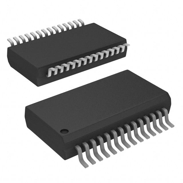
- Part No.:
- MCW1001A-I/SS
- Manufacturer:
- Microchip Technology
- Category:
- Specialized
- Package:
- 28-SSOP (0.209", 5.30mm Width)
- Datasheet:
-
 MCW1001A-I/SS.pdf
- Description:
- IC INTERFACE SPECIALIZED 28SSOP
- Quantity:
- Payment:

- Shipping:

Inventory:2,284
Please send an inquiry. Send us your inquiry, and we will respond immediately.
Product details
Overview
MCW1001A-I/SS from Microchip Technology is a TCP/IP socket communications interface IC designed as a companion controller for the MRF24WB0MA/MB 802.11 Wi-Fi modules. It integrates an on-board TCP/IP stack, 802.11 connection manager, UART interface (up to 230 Kbaud), 8 GPIOs, and operates from 2.7V–3.6V. It enables embedded microcontrollers without native Wi-Fi or TCP/IP capability to establish BSD socket-based network communication in smart energy and industrial IoT applications.
For engineers reviewing the MCW1001A-I/SS datasheet, MCW1001A-I/SS pinout, MCW1001A-I/SS application, or MCW1001A-I/SS equivalent, this page delivers verified technical context, validated pin functions, real-world use scenarios, and confirmed alternative options for wireless connectivity integration with UART-hosted systems.
Technical Context
The MCW1001A-I/SS implements a dedicated UART-to-Wi-Fi bridge architecture, using a proprietary WSPI interface (WCS, WSCK, WSDI, WSDO) to control and exchange data with the MRF24WB0M transceiver. Its internal TCP/IP stack handles socket creation, binding, connection, and data transmission/reception via standardized BSD-style messaging commands over UART.
It features dual-domain I/O: GPIO<0:4> support medium-drive indication functions, while GPIO<5:7> tolerate 5.5V inputs and deliver high-drive capability for LED loads. The device relies on an external 8 MHz crystal (OSC1/OSC2), requires a 10 µF VCAP capacitor for regulator stability, and uses active-low RESET with integrated noise filtering.
Key Specifications
| Parameter | Value and Actual Design Meaning |
|---|---|
| Interface | UART (UTX/URX) with optional hardware flow control (URTS/UCTS); WSPI control bus for MRF24WB0M |
| Operating Voltage | 2.7V–3.6V - compatible with standard 3.3V logic systems; no level-shifting required for host MCU |
| UART Baud Rate | Up to 230 Kbaud - supports high-throughput serial data transfer between host and Wi-Fi stack |
| GPIO Count & Type | 8 bidirectional digital I/O - GPIO<0:4> medium-drive (indication), GPIO<5:7> high-drive & 5.5V-tolerant (LED/load control) |
| Temperature Range | −40°C to +85°C - qualified for industrial environments including smart meters and HVAC controls |
| Crystal Frequency | 8 MHz - fixed-frequency oscillator input required for timing-critical Wi-Fi and TCP/IP operations |
| Current Consumption | 10 mA typical operational current - enables low-power wireless node design when paired with MRF24WB0M sleep modes |
Pinout & Package
MCW1001A-I/SS is housed in a 28-pin SSOP (Shrink Small Outline Package) with 0.65 mm pitch, footprint code SS, and JEDEC MS-012AC compliant dimensions (9.9 mm × 3.9 mm). The package includes two ground pins (VSS at Pins 8 and 19), dual power domains (VDD at Pin 20, VCAP at Pin 6), and dedicated control lines for MRF24WB0M interfacing.
| Pin/Terminal | Circuit Role | Design Meaning |
|---|---|---|
| RESET | Active-low reset input | Asynchronous system reset; includes internal noise filter to reject glitches <100 ns |
| UTX / URX | UART transmit / receive | Full-duplex asynchronous serial interface; default 115200 baud, 8N2 format after reset |
| WCS / WSCK / WSDO / WSDI | WSPI slave select, clock, output, input | 4-wire SPI-like interface to MRF24WB0M; synchronous command/data exchange for Wi-Fi control |
| WINT | Interrupt input from MRF24WB0M | Level-sensitive signal indicating pending data or event; must be pulled high via 4.7 kΩ resistor |
| WRST / WHIB / WWP | Reset, hibernate, write-protect outputs to MRF24WB0M | Direct hardware control of MRF24WB0M power states and flash protection; eliminates host software overhead |
| GPIO0–GPIO7 | General-purpose digital I/O | Configurable per-pin drive strength and voltage tolerance; GPIO5–GPIO7 support 5.5V inputs and LED drive |
| VCAP | Voltage regulator filter capacitor terminal | Requires 10 µF low-ESR capacitor to ground; stabilizes internal LDO output for Wi-Fi subsystem reliability |
Key Features
| Feature | Design Value |
|---|---|
| Built-in TCP/IP & 802.11 connection manager | Offloads full network stack processing from host MCU; enables socket API usage without embedded OS or protocol expertise |
| BSD socket messaging interface | Standardized UART command set (e.g., SOCKET_CREATE_MSG, WIFI_CONNECT_MSG) simplifies firmware development and interoperability |
| No external memory required | Self-contained operation - all stack state, buffers, and configuration stored internally; reduces BOM count and PCB area |
| Seamless MRF24WB0M integration | Dedicated WSPI interface and control signals (WRST, WHIB, WWP) provide deterministic hardware-level coordination with Wi-Fi module |
| Industrial temperature range support | Validated operation from −40°C to +85°C ensures reliability in utility metering, HVAC, and remote sensor deployments |
Applications
| Smart Energy Metering | Industrial Remote Monitoring |
|---|---|
|
Use Scenario: Two-way communication in ANSI C12.19-compliant smart electricity meters transmitting consumption data and receiving firmware updates over public or private 802.11 networks. IC Role / Device Role / Timing Role: TCP/IP socket interface bridging the meter's main MCU to the MRF24WB0M Wi-Fi module; handles DHCP, socket management, and secure packet framing. Use Value: Eliminates need for custom Wi-Fi stack porting; enables rapid certification-ready deployment using Microchip's pre-validated networking layer. |
Use Scenario: Wireless chemical sensor nodes in hazardous industrial zones reporting real-time gas concentration and temperature to cloud platforms via local Wi-Fi access points. IC Role / Device Role / Timing Role: UART-connected network coprocessor managing Wi-Fi association, TLS handshake setup, and buffered socket transmission under intermittent power conditions. Use Value: Reduces host MCU firmware complexity by abstracting low-level 802.11 state machines and TCP retransmission logic into reliable message-based commands. |
| Home Security Hub | Medical Device Connectivity |
|
Use Scenario: Central security panel aggregating Z-Wave or wired sensor inputs and relaying alarm events, video thumbnails, and arming status to mobile apps via home Wi-Fi. IC Role / Device Role / Timing Role: Dedicated Wi-Fi interface IC handling concurrent UDP heartbeat and TCP alarm reporting channels; GPIOs drive status LEDs and buzzer alerts. Use Value: Enables deterministic latency for critical alarm delivery while isolating RF interference from sensitive analog sensor circuitry on the main board. |
Use Scenario: Glucose meter uploading encrypted blood sugar readings to HIPAA-compliant cloud services through authenticated Wi-Fi sessions during patient clinic visits. IC Role / Device Role / Timing Role: Secure socket endpoint managing WPA-PSK authentication, TLS session establishment, and fragmented HTTP POST payloads over constrained UART bandwidth. Use Value: Provides certified cryptographic offload and network resilience without requiring host MCU resources or exposing keys in application firmware. |
Equivalent & Alternatives
The following parts are listed as comparable options for similar TCP/IP-to-Wi-Fi interface applications.
| Alternative Part | Technical Difference | Application Difference | Selection Advice |
|---|---|---|---|
| MRF24WG0MA-I/RM | Integrated 802.11g SoC with built-in TCP/IP stack and 2.4 GHz radio; no companion chip needed; requires external flash for firmware storage | Eliminates inter-chip WSPI interface but demands more host MCU resources for driver integration and larger PCB layout for antenna matching | Select when minimizing component count and board space outweighs need for modular Wi-Fi upgrade path |
| ESP32-WROOM-32 | Dual-core Xtensa LX6 MCU with integrated 2.4 GHz Wi-Fi/BT, rich AT command set, and 4 MB flash; operates at 3.3V but GPIOs not 5.5V tolerant | Offers higher processing autonomy and BLE coexistence but lacks native BSD socket UART API; requires deeper firmware adaptation | Select when application requires local decision-making, OTA updates, or Bluetooth functionality alongside Wi-Fi |
Compared with MRF24WG0MA-I/RM and ESP32-WROOM-32, the MCW1001A-I/SS provides a strictly UART-transparent, drop-in socket interface with zero host MCU TCP/IP stack dependency - ideal for legacy 8-bit/16-bit microcontrollers where resource headroom and certification reuse are critical.
Availability
MCW1001A-I/SS is available at Aetrix Electronics and suitable for smart metering, industrial remote monitoring, home security hubs, and medical device connectivity requiring stable component supply and long-term industrial lifecycle support.
Supply support for MCW1001A-I/SS includes scheduled delivery planning, volume procurement assistance, BOM continuity management, traceable sourcing, and lifecycle availability coordination for OEM customers, industrial embedded developers, connected-device designers, and electronics production programs.
Manufacturer
Microchip Technology Inc. is a leading provider of microcontroller, mixed-signal, analog, and Flash-IP solutions, headquartered in Chandler, Arizona, with ISO/TS-16949:2009 certified manufacturing facilities.
The MCW1001A-I/SS belongs to Microchip's Wi-Fi companion IC product line, engineered specifically to simplify wireless connectivity for resource-constrained host microcontrollers using standardized UART and BSD socket abstractions.
FAQ
What is the primary function of the MCW1001A-I/SS in a wireless system?
The MCW1001A-I/SS serves as a TCP/IP socket communications interface IC that bridges a host microcontroller's UART to the MRF24WB0MA/MB 802.11 Wi-Fi module. It executes the full TCP/IP stack and 802.11 connection management internally, allowing the host to issue simple UART-based BSD socket commands - such as SOCKET_CREATE_MSG or WIFI_CONNECT_MSG - without implementing network protocols in firmware. This makes MCW1001A-I/SS essential for adding robust Wi-Fi connectivity to legacy or low-resource MCUs.
Does the MCW1001A-I/SS require external memory to operate?
No, the MCW1001A-I/SS operates without external memory. All required firmware, TCP/IP stack state, socket buffers, and configuration data are stored internally. This eliminates the need for external Flash or RAM components, reducing BOM cost, PCB area, and qualification effort - a key advantage confirmed in the DS70671A datasheet under "Key Features" and validated across Sections 1.0 and 7.0.
How does the MCW1001A-I/SS interface with the MRF24WB0M Wi-Fi module?
The MCW1001A-I/SS interfaces with the MRF24WB0M using a dedicated 4-wire WSPI bus (WCS, WSCK, WSDO, WSDI), plus control signals WRST, WHIB, WWP, and interrupt line WINT. This hardware-coordinated interface allows the MCW1001A-I/SS to manage the MRF24WB0M's power states, initiate scans, handle association, and exchange packets - all without host MCU involvement. Pin definitions and timing requirements are fully specified in Table 1-1 and Section 2.4 of the DS70671A datasheet.
What are the voltage and drive characteristics of the GPIO pins on the MCW1001A-I/SS?
The MCW1001A-I/SS features eight GPIOs divided into two groups: GPIO<0:4> offer medium-drive capability suited for status indicators, while GPIO<5:7> provide high-drive output and tolerate up to 5.5V input - enabling direct LED driving and safe interfacing with +5V logic systems using pull-up configurations. These distinctions are explicitly defined in Tables 2-1 and 2-2 of the DS70671A datasheet and confirmed in Section 2.5.
Can the MCW1001A-I/SS support secure Wi-Fi connections like WPA/WPA2?
Yes, the MCW1001A-I/SS supports WPA and WPA2-PSK security through dedicated UART API commands including SET_CP_SECURITY_WPA_MSG and GET_CP_WPAKEY_MSG. It performs on-device WPA key derivation and manages the full 4-way handshake with the access point, returning success/failure responses via WPAKEY_RESPONSE_MSG. This capability is documented in Table 1-2 (Wi-Fi Security Configuration Messages) and verified in Section 4.0 of the DS70671A datasheet.
MCW1001A-I/SS Specifications
- Product attributes
- Attribute value
- Manufacturer:
- Microchip Technology
- Series:
- -
- Package/Case:
- 28-SSOP (0.209", 5.30mm Width)
- Packaging:
- Tube
- Product Status:
- Active
- Applications:
- Communications Controller
- Interface:
- UART
- Voltage - Supply:
- 2.7V ~ 3.6V
- Supplier Device Package:
- 28-SSOP
- Grade:
- -
- Qualification:
- -
- Mounting Type:
- Surface Mount
MCW1001A-I/SS FAQ
1.How can I place an order for MCW1001A-I/SS through Aetrix?
Please submit a Request for Quotation (RFQ) for MCW1001A-I/SS on Aetrix. Our sales agent will provide a competitive quotation and guide you through the order confirmation once you accept the terms.
2.Are the price and stock information for MCW1001A-I/SS reliable?
The price and inventory of MCW1001A-I/SS are updated periodically and may fluctuate due to market conditions. Stock and pricing data are typically refreshed every 24 hours. Quotation validity for MCW1001A-I/SS is usually 5 days.
3.What payment methods are accepted for MCW1001A-I/SS?
We accept Wire Transfer, PayPal, Credit Card, Western Union, MoneyGram, and Escrow for MCW1001A-I/SS transactions.
Note: Certain payment methods may incur a processing fee.
4.How is shipping managed for MCW1001A-I/SS?
MCW1001A-I/SS orders can be shipped via leading logistics carriers, including DHL, UPS, FedEx, TNT, or Registered Mail.
Once your MCW1001A-I/SS order is processed, you will receive an email with the shipment details and tracking number.
Note: Tracking information may take up to 24 hours to appear. Express delivery typically takes 3–5 business days.
5.How can I obtain technical support or documentation for MCW1001A-I/SS?
For technical support, including MCW1001A-I/SS datasheets, pinout diagrams, or application guidance, please contact our engineering support team. They can provide detailed documentation and assistance for your MCW1001A-I/SS requirements.
6.How does Aetrix verify that MCW1001A-I/SS is sourced from the original manufacturer or authorized distributors?
All MCW1001A-I/SS products on Aetrix are procured from qualified distributors and authorized channels. Our dedicated quality assurance team conducts strict verification, including traceability checks and, if necessary, third-party testing. This ensures that MCW1001A-I/SS meets industry standards.
7.What is the process for return or replacement of MCW1001A-I/SS?
All MCW1001A-I/SS units undergo pre-shipment inspection (PSI). If there is an issue with MCW1001A-I/SS, returns or replacements are accepted under the following conditions:
1.Quantity discrepancies, incorrect items, or visible external defects (such as breakage or corrosion), acknowledged by Aetrix.
2.The issue is reported within 90 days of delivery.
3.The MCW1001A-I/SS part is unused and in its original packaging.
Return procedure for MCW1001A-I/SS:
1.Submit a request within 90 days.
2.Obtain a Return Material Authorization (RMA) from Aetrix.
MCW1001A-I/SS Tags

-
NVT4857UKAZ
NXP Semiconductors

-
TCA8418RTWR
Texas Instruments

-
PCA9546APWR
Texas Instruments

-
MD0100N8-G
Microchip Technology

-
PCA9548APW,118
NXP Semiconductors

-
PCA9540BDP,118
NXP Semiconductors

-
PCA9548APWR
Texas Instruments

-
PCA9546APW,118
NXP Semiconductors

-
PTN3360DBS,518
NXP Semiconductors

-
PCA9546ABS,118
NXP Semiconductors

-
PCA9518PWR
Texas Instruments

-
PCA9545APW,118
NXP Semiconductors
Tech Hub

TTL and CMOS logic families differ in thresholds, loading, output drive, power and timing. This engineering guide compares 74HC and 74HCT, calculates noise margins and checks 3.3 V/5 V compatibility.

A practical engineering guide to 3.3V and 5V logic compatibility, input thresholds, resistor dividers, translator ICs, MOSFET level shifting, I2C pull-ups, timing limits and power-sequencing risks.

The 74HC595 uses push-pull logic outputs, while the TPIC6B595 uses 50 V open-drain DMOS sinks for higher-power loads. This guide compares timing, current limits, 3.3 V interfacing, load wiring, thermal…

The 74HC595 converts serial data into eight stable parallel outputs. This guide covers pin functions, shift and storage timing, OE and MR behavior, drive-current limits, cascading, voltage compatibilit…

A technical comparison of level-sensitive latches and edge-triggered flip-flops, covering timing windows, setup and hold limits, master–slave operation, time borrowing, race-through, HDL inference and…

A D latch stores one bit while Enable controls when data can pass. This reference covers gate-level operation, truth tables, transparency, setup and hold timing, LE versus OE, common ICs and practical …

An SR latch stores one bit through cross-coupled feedback. This engineering reference covers NOR and NAND implementations, truth tables, forbidden-state recovery, gated operation, switch debouncing, fa…

Latch circuits retain one bit through feedback. This technical reference covers SR and D latches, truth tables, transparency, timing limits, latch-versus-flip-flop behavior, applications and common log…

An engineering guide to LED driver operation, constant-current and constant-voltage outputs, linear and switching topologies, dimming, IC selection, calculations, replacement compatibility, and fault c…

Operational amplifier guide covering op amp basics, feedback, ideal vs real op amps, common configurations, buffer circuits, offset, bias current, gain-bandwidth, slew rate, rail-to-rail limits and sel…


